717 Engines
717 Engines
717 Engines

You also want an ePaper? Increase the reach of your titles
YUMPU automatically turns print PDFs into web optimized ePapers that Google loves.
Section 04 ENGINE (2-STROKE)<br />
Subsection 04 (TOP END)<br />
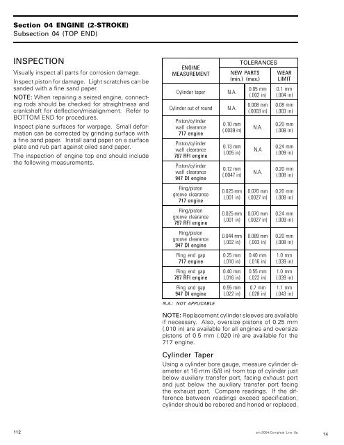
INSPECTION<br />
Visually inspect all parts for corrosion damage.<br />
Inspect piston for damage. Light scratches can be<br />
sanded with a fine sand paper.<br />
NOTE: When repairing a seized engine, connecting<br />
rods should be checked for straightness and<br />
crankshaft for deflection/misalignment. Refer to<br />
BOTTOM END for procedures.<br />
Inspect plane surfaces for warpage. Small deformation<br />
can be corrected by grinding surface with<br />
a fine sand paper. Install sand paper on a surface<br />
plate and rub part against oiled sand paper.<br />
The inspection of engine top end should include<br />
the following measurements.<br />
ENGINE<br />
MEASUREMENT<br />
Cylinder taper N.A.<br />
Cylinder out of round N.A.<br />
Piston/cylinder<br />
wall clearance<br />
<strong>717</strong> engine<br />
Piston/cylinder<br />
wall clearance<br />
787 RFI engine<br />
Piston/cylinder<br />
wall clearance<br />
947 DI engine<br />
Ring/piston<br />
groove clearance<br />
<strong>717</strong> engine<br />
Ring/piston<br />
groove clearance<br />
787 RFI engine<br />
Ring/piston<br />
groove clearance<br />
947 DI engine<br />
Ring end gap<br />
<strong>717</strong> engine<br />
Ring end gap<br />
787 RFI engine<br />
Ring end gap<br />
947 DI engine<br />
N.A.: NOT APPLICABLE<br />
TOLERANCES<br />
NEW PARTS<br />
(min.) (max.)<br />
0.10 mm<br />
(.0039 in)<br />
0.13 mm<br />
(.005 in)<br />
0.12 mm<br />
(.0047 in)<br />
0.025 mm<br />
(.001 in)<br />
0.025 mm<br />
(.001 in)<br />
0.044 mm<br />
(.002 in)<br />
0.25 mm<br />
(.010 in)<br />
0.40 mm<br />
(.016 in)<br />
0.55 mm<br />
(.022 in)<br />
0.05 mm<br />
(.002 in)<br />
0.008 mm<br />
(.0003 in)<br />
N.A.<br />
N.A<br />
N.A.<br />
0.070 mm<br />
(.0027 in)<br />
0.070 mm<br />
(.0027 in)<br />
0.089 mm<br />
(.003 in)<br />
0.40 mm<br />
(.016 in)<br />
0.55 mm<br />
(.022 in)<br />
0.7 mm<br />
(.028 in)<br />
WEAR<br />
LIMIT<br />
0.1 mm<br />
(.004 in)<br />
0.08 mm<br />
(.003 in)<br />
0.20 mm<br />
(.008 in)<br />
0.24 mm<br />
(.009 in)<br />
0.20 mm<br />
(.008 in)<br />
0.20 mm<br />
(.008 in)<br />
0.24 mm<br />
(.009 in)<br />
0.20 mm<br />
(.008 in)<br />
1.0 mm<br />
(.039 in)<br />
1.0 mm<br />
(.039 in)<br />
1.1 mm<br />
(.043 in)<br />
NOTE: Replacement cylinder sleeves are available<br />
if necessary. Also, oversize pistons of 0.25 mm<br />
(.010 in) are available for all engines and oversize<br />
pistons of 0.5 mm (.020 in) are available for the<br />
<strong>717</strong> engine.<br />
Cylinder Taper<br />
Using a cylinder bore gauge, measure cylinder diameter<br />
at 16 mm (5/8 in) from top of cylinder just<br />
below auxiliary transfer port, facing exhaust port<br />
and just below the auxiliary transfer port facing<br />
the exhaust port. Compare readings. If the difference<br />
between readings exceed specification,<br />
cylinder should be rebored and honed or replaced.<br />
112 smr2004-Complete Line Up<br />
14