717 Engines
717 Engines
717 Engines

Create successful ePaper yourself
Turn your PDF publications into a flip-book with our unique Google optimized e-Paper software.
Section 04 ENGINE (2-STROKE)<br />
Subsection 06 (ROTARY VALVE)<br />
GENERAL<br />
The following verification procedures such as<br />
clearance of rotary valve cover or rotary valve<br />
shaft gear backlash can be performed without<br />
removing engine from watercraft.<br />
However engine must be removed from watercraft<br />
to work on rotary valve shaft/components.<br />
Refer to REMOVAL AND INSTALLATION for engine<br />
removal procedure.<br />
Bottom end must be opened to remove rotary<br />
valve shaft. Refer to BOTTOM END.<br />
INSPECTION ON WATERCRAFT<br />
Remove carburetor(s). Refer to CARBURETOR.<br />
Rotary Valve Cover<br />
Unscrew 4 screws no. 2 and withdraw rotary<br />
valve cover no. 1.<br />
Remove rotary valve no. 13.<br />
Rotary Valve/Cover Clearance<br />
The clearance between the rotary valve and the<br />
cover must be 0.25 – 0.35 mm (.010 –.014 in).<br />
NOTE: If the clearance is lower, this could create<br />
an overheating situation and if the clearance is<br />
higher, this could create a hard starting situation.<br />
There are 2 methods to verify rotary valve/cover<br />
clearance:<br />
– the 45° feeler gauge method<br />
– the soldering wire method.<br />
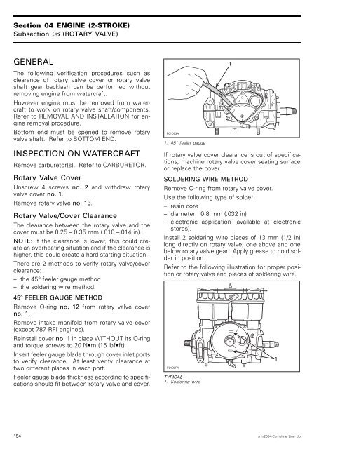
45° FEELER GAUGE METHOD<br />
Remove O-ring no. 12 from rotary valve cover<br />
no. 1.<br />
Remove intake manifold from rotary valve cover<br />
(except 787 RFI engines).<br />
Reinstall cover no. 1 in place WITHOUT its O-ring<br />
andtorquescrewsto20N m(15lbfft). Insert feeler gauge blade through cover inlet ports<br />
to verify clearance. At least verify clearance at<br />
two different places in each port.<br />
Feeler gauge blade thickness according to specifications<br />
should fit between rotary valve and cover.<br />
F01D53A<br />
1. 45° feeler gauge<br />
1<br />
If rotary valve cover clearance is out of specifications,<br />
machine rotary valve cover seating surface<br />
or replace the cover.<br />
SOLDERING WIRE METHOD<br />
Remove O-ring from rotary valve cover.<br />
Use the following type of solder:<br />
– resin core<br />
– diameter: 0.8 mm (.032 in)<br />
– electronic application (available at electronic<br />
stores).<br />
Install 2 soldering wire pieces of 13 mm (1/2 in)<br />
long directly on rotary valve, one above and one<br />
below rotary valve gear. Apply grease to hold solder<br />
in position.<br />
Refer to the following illustration for proper position<br />
or rotary valve and pieces of soldering wire.<br />
F01D3PA<br />
TYPICAL<br />
1. Soldering wire<br />
154 smr2004-Complete Line Up<br />
1