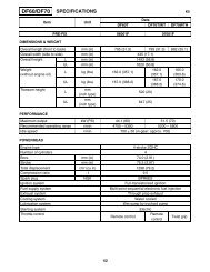
717 Engines
717 Engines
717 Engines

Create successful ePaper yourself
Turn your PDF publications into a flip-book with our unique Google optimized e-Paper software.
Section 04 ENGINE (2-STROKE)<br />
Subsection 05 (BOTTOM END)<br />
F01D1QA<br />
1. Ruler must be aligned with edge of connecting rod here<br />
2. Align ruler here<br />
Crankshaft Deflection<br />
All Models<br />
MEASUREMENT MAG SIDE PTO SIDE<br />
Crankshaft<br />
deflection (max.)<br />
2<br />
0.050 mm<br />
(.002 in)<br />
1<br />
0.030 mm<br />
(.001 in)<br />
Crankshaft deflection is measured each end with<br />
a dial indicator.<br />
First, check deflection with crankshaft in<br />
crankcase. If deflection exceeds the specified<br />
tolerance, it can be either ball bearings wear, bent<br />
or twisted crankshaft at connecting rod journal.<br />
F01D1SA<br />
1. Measuring PTO side deflection in crankcase<br />
1<br />
F01D1TA<br />
1<br />
1. Measuring MAG side deflection in crankcase<br />
Remove crankshaft bearings and check deflection<br />
again on V-shaped blocks as illustrated.<br />
F01D97A<br />
1<br />
1. Measuring MAG side deflection on V-shaped blocks<br />
F01D98A<br />
1. Measuring PTO side deflection on V-shaped blocks<br />
142 smr2004-Complete Line Up<br />
1