POHYBOVÉ ÚSTROJÍ - Společnost pro pojivové tkáně
POHYBOVÉ ÚSTROJÍ - Společnost pro pojivové tkáně
POHYBOVÉ ÚSTROJÍ - Společnost pro pojivové tkáně

You also want an ePaper? Increase the reach of your titles
YUMPU automatically turns print PDFs into web optimized ePapers that Google loves.
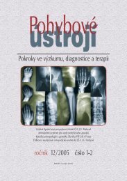
Fig. 4. FE model of the C/C plate Table 4. Stresses in the C/C plate<br />
plane symmetry of the real plates M = 600 The C/C plate<br />
(FE analysis) and the limit bending moment According to the FEM computation, the<br />
at the plane symmetry of the real plates failure of the C/C plate under investigation<br />
M MAX.<br />
The Tsai-Hill strength criterion is usually<br />
used for evaluating composite structures.<br />
was caused by the maximum bending<br />
moment of M MAX = 18400 acting in the<br />
middle of the plate (i.e., at the plane of<br />
However, the criterion requires knowledge symmetry xy). In Fig.4, one quarter of the<br />
of the strengths of a layer in tension, in plate FE mesh is plotted, and several<br />
compression (in the fibre/warp direction nodes, at which a critical stress state can be<br />
and in the perpendicular direction to the expected, are denoted by numbers: i) at the<br />
fibres/warp) and in shear. In our case, the plane of symmetry xy; ii) at the screw hole 1<br />
strength in tension, and in compression, in position close to the plane of symmetry xy.<br />
the warp direction and in the direction Corresponding stresses for these nodes are<br />
perpendicular to the warp were known. listed in Table 4. The node numbered 1784<br />
Hence the maximum stress strength re p re s e n t s t h e m a x i m u m s t re s s<br />
criterion was used. corresponding to the failure bending<br />
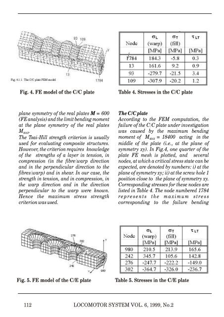
Fig. 5. FE model of the C/E plate Table 5. Stresses in the C/E plate<br />
112<br />
LOCOMOTOR SYSTEM VOL. 6, 1999, No.2