Appendix D Overview of the Sea Water Scrubber System - Holland ...
Appendix D Overview of the Sea Water Scrubber System - Holland ...
Appendix D Overview of the Sea Water Scrubber System - Holland ...

You also want an ePaper? Increase the reach of your titles
YUMPU automatically turns print PDFs into web optimized ePapers that Google loves.
<strong>Appendix</strong> D<br />
<strong>Overview</strong> <strong>of</strong> <strong>the</strong> <strong>Sea</strong> <strong>Water</strong> <strong>Scrubber</strong> <strong>System</strong><br />
The Krystallon sea water scrubber was constructed <strong>of</strong> very high quality alloy (patents are pending on this<br />
material) and is designed to last <strong>the</strong> life <strong>of</strong> <strong>the</strong> vessel. The scrubber design incorporates numerous o<strong>the</strong>r<br />
internal patented technologies to ensure very high mass transfer and scrubbing efficiency. After<br />
scrubbing, <strong>the</strong> wash water is sent to a multicyclone. This treated wash water is <strong>the</strong>n mixed with<br />
additional seawater to adjust <strong>the</strong> pH prior to overboard discharge. The main components <strong>of</strong> <strong>the</strong><br />
shipboard system include:<br />
• <strong>Water</strong> intake through a sea chest.<br />
• <strong>Sea</strong> water scrubber (called “exhaust gas scrubber” below)<br />
• Multicyclone<br />
• Pumps, Valves, Instruments, and Associated Piping<br />
• <strong>Water</strong> discharge port<br />
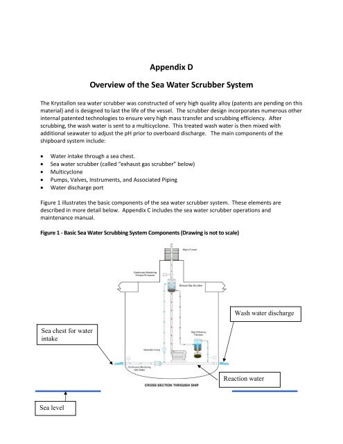
Figure 1 illustrates <strong>the</strong> basic components <strong>of</strong> <strong>the</strong> sea water scrubber system. These elements are<br />
described in more detail below. <strong>Appendix</strong> C includes <strong>the</strong> sea water scrubber operations and<br />
maintenance manual.<br />
Figure 1 ‐ Basic <strong>Sea</strong> <strong>Water</strong> Scrubbing <strong>System</strong> Components (Drawing is not to scale)<br />
<strong>Sea</strong> chest for water<br />
intake<br />
<strong>Sea</strong> level<br />
Wash water discharge<br />
Reaction water
<strong>Water</strong> Intake through <strong>the</strong> <strong>Sea</strong> Chest<br />
<strong>Water</strong> is taken aboard a vessel through a device called a sea chest. A sea chest is a rectangular steel<br />
enclosure attached to <strong>the</strong> inside <strong>of</strong> a louvered or perforated section <strong>of</strong> <strong>the</strong> ship’s hull below <strong>the</strong> water<br />
line. <strong>Water</strong> enters <strong>the</strong> sea chest, and when <strong>the</strong> valve is open, water passes into <strong>the</strong> pipe and through<br />
<strong>the</strong> strainer into <strong>the</strong> ship, where it is delivered for its intended use. The strainer is cleaned periodically<br />
to remove accumulated solid material (sea weed, twigs, etc). When <strong>the</strong> valve is closed, sea water does<br />
not enter <strong>the</strong> ship.<br />
The <strong>Sea</strong> <strong>Water</strong> <strong>Scrubber</strong><br />
Exhaust gas passes through <strong>the</strong> scrubber where it is mixed with raw seawater. There are no chemicals<br />
added anywhere in this system. Several stages <strong>of</strong> seawater and gas mixing occur to ensure high levels <strong>of</strong><br />
scrubbing efficiency. The scrubbing cools <strong>the</strong> gas and entrains droplets <strong>of</strong> seawater. A “demister” was<br />
installed in order to prevent <strong>the</strong>se droplets <strong>of</strong> seawater from being carried out <strong>of</strong> <strong>the</strong> stack. As <strong>the</strong><br />
scrubber was not operated in port pending demonstration <strong>of</strong> <strong>the</strong> wash water technology, <strong>the</strong> demister<br />
was subject to frequent dry operation which resulted in clogging. This clogging problem precluded use<br />
<strong>of</strong> <strong>the</strong> demister during much <strong>of</strong> this demonstration project. To minimize generation <strong>of</strong> a vapor plume,<br />
<strong>the</strong> wash water supply in <strong>the</strong> final scrubbing stage was switched <strong>of</strong>f and it was <strong>the</strong>n used as <strong>the</strong><br />
demister.<br />
After scrubbing, <strong>the</strong> cooled exhaust gas is re‐heated using a hot air injection manifold to change <strong>the</strong><br />
relative humidity <strong>of</strong> <strong>the</strong> gas from 100% to less than 80%. This prevents a visible plume at <strong>the</strong> funnel<br />
outlet.<br />
Wash water (<strong>the</strong> effluent from <strong>the</strong> scrubber) flows out <strong>of</strong> <strong>the</strong> base <strong>of</strong> <strong>the</strong> scrubber unit to <strong>the</strong><br />
multicyclone below deck in <strong>the</strong> engine room.<br />
The Multicyclone ‐ Wash <strong>Water</strong> Treatment Plant<br />
After leaving <strong>the</strong> scrubber, <strong>the</strong> wash water passes through a high performance multicyclone, which<br />
separates <strong>the</strong> particles from <strong>the</strong> wash water. The pH <strong>of</strong> <strong>the</strong> treated wash water is <strong>the</strong>n raised to a near<br />
neutral value by mixing with an essentially equal volume <strong>of</strong> “reaction water,” (see Figure 1 above)<br />
delivered by a separate reaction water supply line before being discharged overboard to <strong>the</strong> sea.<br />
This particulate removed by <strong>the</strong> multicyclone is collected in a chamber in <strong>the</strong> base <strong>of</strong> <strong>the</strong> unit (see Figure<br />
2), from where it is batch ejected to a storage tank (see Figure 3).<br />
Figure 2 ‐ The Multicyclone
Figure 3 – The Sludge Storage Tank<br />
Note: The dimension <strong>of</strong> <strong>the</strong> storage tank is approximately 4 feet by 2.5 feet by 3 feet. It holds<br />
approximately 0.65 cubic meters <strong>of</strong> sludge.
Reaction <strong>Water</strong><br />
Reaction water is added to <strong>the</strong> system after <strong>the</strong> wash water is treated through <strong>the</strong> multicyclone. The<br />
function <strong>of</strong> <strong>the</strong> reaction water is to neutralize <strong>the</strong> pH <strong>of</strong> <strong>the</strong> wash water prior to discharge overboard.<br />
Reaction water is added to <strong>the</strong> wash water in nearly equal proportions i.e. approximately 400 tons <strong>of</strong><br />
water is pumped up through <strong>the</strong> scrubber (<strong>the</strong> wash water) and approximately 500 tons <strong>of</strong> reaction<br />
water is added after <strong>the</strong> multicyclone.<br />
Using reaction water to neutralize <strong>the</strong> pH improves energy efficiency <strong>of</strong> <strong>the</strong> system. The pH <strong>of</strong> <strong>the</strong><br />
discharge would be <strong>the</strong> same whe<strong>the</strong>r 900 tons <strong>of</strong> water per hour were pumped up through <strong>the</strong><br />
scrubber or whe<strong>the</strong>r 400 tons were pumped up 10 decks and ano<strong>the</strong>r 500 tons are pumped horizontally.<br />
This system is more than twice as energy efficient than a system which pumps all 900 tons up 10 decks.<br />
Pumps, Valves, and Piping<br />
There are two pumps included in this system. The wash water supply pump is a standard seawater<br />
pump designed to supply sufficient seawater to maintain design efficiency <strong>of</strong> <strong>the</strong> scrubber at normal<br />
operating loads <strong>of</strong> <strong>the</strong> engine as specified by <strong>the</strong> engine manufacturer. The reaction water supply pump<br />
is a standard seawater pump designed to supply sufficient seawater to achieve maximum pH in <strong>the</strong><br />
discharge.<br />
The system is designed to be self‐regulating. All <strong>of</strong> <strong>the</strong> valves are fitted to isolate <strong>the</strong> system only during<br />
maintenance activities and/or extended shut down. There is no manual operation <strong>of</strong> <strong>the</strong> valves during<br />
normal conditions. The valves are designed to cope with <strong>the</strong> chemical, temperature, and physical<br />
conditions <strong>of</strong> <strong>the</strong> wash water and/or engine exhaust.<br />
Piping is manufactured from GRE (glass reinforced epoxy), a very inert material which is easy to handle<br />
and install and has low flow resistance thus saving on wash water pumping energy. GRE piping is<br />
designed to outlast <strong>the</strong> life <strong>of</strong> <strong>the</strong> ship.<br />
Instrumentation and Control<br />
The system operates automatically with <strong>the</strong> minimal interaction by ship staff; <strong>the</strong>re is simply an “ON”<br />
button and an “OFF” button. The monitoring system is contained in <strong>the</strong> Human Machine interface (HMI)<br />
and is used to monitor <strong>the</strong> operation <strong>of</strong> <strong>the</strong> scrubber system. After <strong>the</strong> initial start up, <strong>the</strong>re is little or no<br />
adjustment required. Pressure drop, temperatures and levels are set by <strong>the</strong> <strong>the</strong>rmodynamics and<br />
hydraulics <strong>of</strong> <strong>the</strong> system, and are not controlled. There is a hard wired safety circuit which protects <strong>the</strong><br />
engine at all times. The batch ejection from <strong>the</strong> multicyclone is carried out once per day.<br />
Signals from <strong>the</strong> various instruments are fed back to <strong>the</strong> HMI, to give live indication <strong>of</strong> <strong>the</strong> operation <strong>of</strong><br />
<strong>the</strong> scrubber. The main indicators include:<br />
• FI100 ‐ wash water flow to <strong>the</strong> scrubber<br />
• PI103 ‐ wash water supply pressure to <strong>the</strong> scrubber<br />
• DPI300 ‐ scrubber pressure drop<br />
• LI301 ‐ level in <strong>the</strong> scrubber
• DPT500 ‐ pressure drop across WT500(water treatment plant)<br />
• Monitoring Manifolds (pH, PAH, turbidity)<br />
• TI301 ‐ temperature at scrubber stack outlet<br />
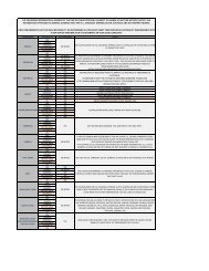
These data are recorded on a secure recording system. The normal operating parameters for <strong>the</strong><br />
system are summarized in Table 2.<br />
Table 1 ‐ Normal Operating Parameters<br />
Measured Value Units Minimum Normal Maximum<br />
Alarm Set<br />
Point<br />
Exhaust Pressures mm H2O<br />
<strong>System</strong> Back Pressure 0 250 350 300<br />
Exhaust Temperatures<br />
o<br />
C<br />
<strong>System</strong> Inlet 300 330‐385 400 420<br />
<strong>Scrubber</strong> Outlet 40 50 60 420<br />
<strong>Water</strong> Flow Rate Tons/hr 350 390 390<br />
<strong>Water</strong> Pressures bar<br />
Wash <strong>Water</strong> Supply 6.2 7.0 8.0 5.5<br />
Reaction <strong>Water</strong> Supply 1.5 2.0 2.5 1.5<br />
<strong>Water</strong> Treatment Plant bar<br />
Differential Pressure 2.0 2.5 2.7 2.8<br />
Sulfur Dioxide 1 ppm<br />
Before <strong>Scrubber</strong> 2 200 770 800 820<br />
After scrubber
<strong>Scrubber</strong> Exhaust<br />
• ES301 ‐ high emissions leaving <strong>the</strong> scrubber (CO2/SO2 ratio value set at 65)<br />
Wash <strong>Water</strong> Discharge<br />
• Low pH in return to sea while in port (pH value set to be 6.5 within 4m <strong>of</strong> <strong>the</strong> ships side)<br />
• High PAH in return to sea (set at 50 ppb maximum)<br />
The safety circuit checks <strong>the</strong> main process parameters <strong>of</strong> <strong>the</strong> scrubber system and will shut <strong>the</strong> system<br />
down in <strong>the</strong> event <strong>of</strong> an unacceptable reading. The main operating parameters that are checked are as<br />
follows:<br />
• LS300 ‐ high water level in <strong>the</strong> scrubber<br />
• DPS300 ‐ high pressure drop across <strong>the</strong> scrubber<br />
• Operation <strong>of</strong> <strong>the</strong> wash water supply pump<br />
• Operation <strong>of</strong> <strong>the</strong> reaction water supply pump<br />
• TS302 ‐ high temperature <strong>of</strong> <strong>the</strong> scrubber shell<br />
In <strong>the</strong> event <strong>of</strong> a malfunction, a signal from <strong>the</strong> safety circuit initiates a shut down <strong>of</strong> <strong>the</strong> wash water<br />
supply pump and also sends an alarm to <strong>the</strong> HMI. The scrubber will be in a run dry mode, ready for<br />
restarting.