EMCO WinNC SINUMERIK 810D/840D Turning Software ...
EMCO WinNC SINUMERIK 810D/840D Turning Software ...
EMCO WinNC SINUMERIK 810D/840D Turning Software ...

Create successful ePaper yourself
Turn your PDF publications into a flip-book with our unique Google optimized e-Paper software.
<strong>EMCO</strong> <strong>WinNC</strong> <strong>SINUMERIK</strong> <strong>810D</strong>/<strong>840D</strong> <strong>Turning</strong><br />
<strong>Software</strong> Description/ <strong>Software</strong> version from 21.00<br />
Ã<br />
<br />
<br />
Ã<br />
<br />
<br />
<br />
<br />
<br />
<strong>EMCO</strong> Maier Ges.m.b.H.<br />
P.O. Box 131<br />
A-5400 Hallein-Taxach/Austria<br />
Phone ++43-(0)62 45-891-0<br />
Fax ++43-(0)62 45-869 65<br />
Internet: www.emco.at<br />
E-Mail: service@emco.at<br />
<br />
<br />
<br />
<br />
<br />
<br />
È<br />
<br />
<br />
<br />
<br />
<br />
Ã<br />
<br />
<br />
<br />
<br />
<br />
<br />
<br />
<br />
<br />
<br />
<br />
<br />
<br />
<br />
<br />
<br />
<br />
<br />
<br />
<br />
<br />
<br />
<br />
<br />
<br />
<br />
<br />
<br />
<br />
<br />
<br />
<br />
<br />
<br />
<br />
<br />
<br />
<strong>Software</strong> Description<br />
<strong>EMCO</strong> <strong>WinNC</strong><br />
<strong>SINUMERIK</strong> <strong>810D</strong>/<strong>840D</strong> <strong>Turning</strong><br />
Ref.No. EN 1815 Edition G2007-06<br />
This manual is electronically available (.pdf) upon request<br />
at any time on the <strong>EMCO</strong> homepage.<br />
<br />
<br />
<br />
<br />
<br />
<br />
<br />
<br />
Ä<br />
<br />
Ç<br />
<br />
<br />
<br />
Å<br />
È
WINNC <strong>SINUMERIK</strong> 810 D / 840 D TURNING<br />
Notice<br />
This software description contains all functions that may be carried out with<br />
<strong>WinNC</strong>. However, the availability of functions is dependent on the machine you<br />
operate with <strong>WinNC</strong>.<br />
All rights reserved, reproduction only by authorization of Messrs. <strong>EMCO</strong> MAIER<br />
© <strong>EMCO</strong> MAIER Gesellschaft m.b.H., Hallein<br />
2
WINNC <strong>SINUMERIK</strong> 810 D / 840 D TURNING<br />
Preface<br />
The <strong>EMCO</strong> <strong>WinNC</strong> <strong>SINUMERIK</strong> <strong>810D</strong>/<strong>840D</strong> <strong>Turning</strong> <strong>Software</strong> is part of the<br />
<strong>EMCO</strong> training concept on PC-basis.<br />
This concept aims at learning the operation and programming of a certain<br />
machine control on the PC.<br />
The milling machines of the <strong>EMCO</strong> PC TURN und CONCEPT TURN series can<br />
be directly controlled via PC by means of the <strong>EMCO</strong> <strong>WinNC</strong> for the <strong>EMCO</strong><br />
TURN.<br />
The operation is rendered very easy by the use of a digitizer or the control<br />
keyboard with TFT flat panel display (optional accessory), and it is didactically<br />
especially valuable since it remains very close to the original control.<br />
Apart of this software description and the machine description a teaching<br />
software CD-ROM "WinTutorial" (CNC examples, operation, description of<br />
instructions and cycles) is in preparation.<br />
This manual does not include the whole functionality of the control software<br />
<strong>SINUMERIK</strong> <strong>810D</strong>/<strong>840D</strong> <strong>Turning</strong>, however emphasis was laid on the simple<br />
and clear illustration of the most important functions so as to achieve a most<br />
comprehensive learning success.<br />
In case any questions or proposals for improving this manual should arise,<br />
please contact us directly:<br />
3<br />
<strong>EMCO</strong> MAIER Gesellschaft m. b. H.<br />
Department for technical documentation<br />
A-5400 Hallein, Austria<br />
PREFACE
WINNC <strong>SINUMERIK</strong> 810 D / 840 D TURNING<br />
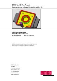
A: Basics .................................................... A 1<br />
Reference Points of the <strong>EMCO</strong> Lathes .................................. A 1<br />
Zero Offset .............................................................................. A 2<br />
Coordinate System ................................................................. A 2<br />
Coordinate System with Absolute Programming ............. A 2<br />
Coordinate System with Incremental Programming ........ A 2<br />
Tool Data ................................................................................. A 3<br />
B: Key Description...................................... B 1<br />
Control Keyboard, Digitizer Overlay ....................................... B 1<br />
Address and Numeric Keyboard ............................................ B 2<br />
Double-Shift Function ...................................................... B 2<br />
Key Functions ......................................................................... B 3<br />
Screen Division ....................................................................... B 4<br />
Machine Control Keys ............................................................ B 5<br />
PC Keyboard .......................................................................... B 7<br />
C: Operation ............................................... C 1<br />
Operation principle ................................................................ C 1<br />
Call basic menu ............................................................... C 1<br />
Navigation in the menu window ...................................... C 1<br />
Navigation in the directories ........................................... C 2<br />
Edit inputs / values .......................................................... C 2<br />
Confirm / cancel input ..................................................... C 3<br />
Mouse operation ............................................................. C 3<br />
Survey Operating Areas ........................................................ C 4<br />
Operating Area Machine ........................................................ C 5<br />
Approach reference point ............................................... C 6<br />
Traverse slides manually ................................................ C 6<br />
Traverse slides in increments ......................................... C 7<br />
MDA mode ....................................................................... C 8<br />
Automatic mode .............................................................. C 8<br />
Operating Area Parameter .................................................... C 9<br />
Tool data .......................................................................... C 9<br />
R Parameter (arithmetic parameter) ............................... C 9<br />
Workpiece counter (R90, R91) ..................................... C 10<br />
Setting data .................................................................... C 11<br />
Zero offset ..................................................................... C 13<br />
Total effefctive zero offset ............................................. C 15<br />
Operating Area Program ..................................................... C 16<br />
Program administration ................................................. C 17<br />
Create workpiece directory ........................................... C 19<br />
Create / edit program .................................................... C 19<br />
Program simulation ....................................................... C 21<br />
Operating Area Services ..................................................... C 23<br />
Interface settings ........................................................... C 23<br />
Drive settings ................................................................ C 23<br />
Read-in data .................................................................. C 24<br />
Send data ...................................................................... C 25<br />
Copying and pasting data from the clipboard ............... C 26<br />
Operating Area Diagnosis ................................................... C 27<br />
Display of software versions ......................................... C 27<br />
Operating Area Start-up ....................................................... C 28<br />
Contents<br />
4<br />
CONTENTS<br />
D: Programming ......................................... D 1<br />
Surveys .................................................................................. D 2<br />
G- commands .................................................................. D 2<br />
M- Commands ................................................................. D 4<br />
Cycles .............................................................................. D 5<br />
Command shortcuts ........................................................ D 6<br />
Arithmetic functions ......................................................... D 8<br />
Calculator ........................................................................ D 9<br />
System variable ............................................................. D 10<br />
Working Movements ............................................................. D 11<br />
G0, G1 Linear interpolation (cartesian) ......................... D 11<br />
G0, G1 Linear interpolation (polar) ................................ D 11<br />
Insert chamfer, radius .................................................... D 11<br />
G2, G3, CIP Circular Interpolation ............................... D 12<br />
G4 Dwell time ................................................................ D 15<br />
G9, G60, G601, G602, G603 Exact positioning ........... D 16<br />
G64, G641 Contouring mode ........................................ D 17<br />
G17, G18, G19 Working plane selection ...................... D 18<br />
G25, G26 Programmable working area limitation ........ D 19<br />
G25, G26 Programmable spindle speed ...................... D 19<br />
G33 Thread cutting ...................................................... D 20<br />
G331/G332 Tapping without compensation chuck ....... D 20<br />
G63 Thread tapping with compenstion chuck .............. D 21<br />
Cutter Radius Compensation G40-G42 ........................ D 22<br />
Zero offsets G53-G57, G500-G599, SUPA ................... D 24<br />
Inch dimensions G70, ................................................... D 24<br />
Metric dimensions G71 ................................................. D 24<br />
Coordinaten, Zero Offset .............................................. D 25<br />
G90 Absolute dimensions ............................................. D 25<br />
G91 Incremental dimensions ........................................ D 25<br />
Working plane G17-G19 ............................................... D 25<br />
Constant cutting speed G96, G97, LIMS ...................... D 26<br />
Feed Programming G94, G95 ...................................... D 26<br />
Polar coordinates G110-G112 ....................................... D 27<br />
Soft approach and leaving G140 - G341, DISR, DISCL,<br />
FAD ................................................................................ D 28<br />
Approach Characteristic NORM, KONT .............................. D 30
WINNC <strong>SINUMERIK</strong> 810 D / 840 D TURNING<br />
Cycle call ............................................................................. D 31<br />
Drilling Cycles ...................................................................... D 33<br />
CYCLE81 Drilling, Centering ........................................ D 34<br />
CYCLE82 Drilling, Counterboring ................................. D 34<br />
CYCLE83 Deep hole drilling ......................................... D 36<br />
CYCLE83E Deep hole drilling ....................................... D 40<br />
CYCLE84 Rigid tapping ................................................ D 42<br />
CYCLE84E Deephole drilling ........................................ D 45<br />
CYCLE840 Tapping with compensation chuck ............. D 47<br />
CYCLE85 Boring 1, CYCLE89 Boring 5 ....................... D 50<br />
CYCLE86 Boring 2 ........................................................ D 51<br />
CYCLE87 Boring 3 ........................................................ D 52<br />
CYCLE88 Boring 4 ........................................................ D 52<br />
<strong>Turning</strong> Cycles ..................................................................... D 54<br />
CYCLE 93 Grooving cycle ............................................ D 55<br />
CYCLE 94 Undercut cycle ............................................ D 59<br />
CYCLE 95 Stock removal cycle .................................... D 61<br />
CYCLE 96 Thread undercut cycle ................................ D 70<br />
CYCLE 97 Thread cutting cycle .................................... D 71<br />
CYCLE 98 Chaining of threads ..................................... D 76<br />
Frames ................................................................................. D 79<br />
Programmable zero offset TRANS, ATRANS ............... D 80<br />
Programmable rotation ROT, AROT ............................. D 81<br />
Programmable scale factor SCALE, ASCALE .............. D 82<br />
Programmable mirroring, MIRROR, AMIRROR ........... D 83<br />
Subprograms ....................................................................... D 85<br />
Subprogram Call in Part Program................................. D 85<br />
Subprogram with SAVE- mechanism ............................ D 86<br />
Subprograms with passing parameters ........................ D 86<br />
Beginning of program, PROC ....................................... D 86<br />
End of program M17, RET ............................................ D 86<br />
Subprogram with program repeating, P ........................ D 86<br />
Modal subprogram MCALL ........................................... D 87<br />
Program jumps .................................................................... D 89<br />
Uncontitional program jumps ........................................ D 89<br />
Conditional program jumps ................................................. D 89<br />
Programming messages, MSG ........................................... D 90<br />
C axis ................................................................................... D 91<br />
Switching on and positioning the C axis ....................... D 91<br />
Deselection of the C axis .............................................. D 91<br />
JOG operation of the C axes ........................................ D 91<br />
Positioning spindles SPOS, SPOSA ................................... D 92<br />
Synchronize spindle movements: ....................................... D 93<br />
WAITS, WAITS (n,n,n) ......................................................... D 93<br />
WAITP(...) ............................................................................ D 94<br />
Extended addresses of Spindle speed S and Spindle rotation<br />
M3, M4, M5,SETMS ............................................................ D 95<br />
TRANSMIT .......................................................................... D 96<br />
TRACYL ............................................................................... D 97<br />
Feed optimizing CFTCP, CFC, CFIN .................................. D 98<br />
Command description M-Commands ................................. D 99<br />
Free contour programming ................................................ D 101<br />
5<br />
CONTENTS<br />
E: Tool Correction / Tool Measuring ........... E 1<br />
Tool Correction ....................................................................... E 1<br />
Tool call ............................................................................ E 1<br />
Tool types ......................................................................... E 3<br />
Tool Measuring ....................................................................... E 6<br />
F: Program Run.......................................... F 1<br />
Preconditions .......................................................................... F 1<br />
Program Selection .................................................................. F 2<br />
Program Start, Program Stop ................................................. F 3<br />
Messages while program run ........................................... F 3<br />
Program Control ..................................................................... F 4<br />
Block Search ........................................................................... F 5<br />
G: Flexible NC- Programming ..................... G1<br />
Variable and arithmetic parameters ....................................... G1<br />
Variable types ................................................................... G1<br />
System variable ................................................................ G1<br />
Variable definition ................................................................... G2<br />
User defined variables ..................................................... G2<br />
Array definition ........................................................................ G3<br />
Array index ....................................................................... G3<br />
Initialization of arrays ....................................................... G3<br />
Initialization of value lists, SET ........................................ G4<br />
Initialization with identical values, REP ............................ G4<br />
Indirect programming ............................................................. G6<br />
Assignments ........................................................................... G6<br />
Assignment to string variables ......................................... G6<br />
Arithmetic operations/functions .............................................. G7<br />
Comparison and logic operations .......................................... G8<br />
Priority of operators .......................................................... G9<br />
Type conversion ..................................................................... G9<br />
Lenght of strings, STRLEN ............................................ G10<br />
CASE statement ................................................................... G11<br />
Check structures ................................................................... G12<br />
IF-ELSE-ENDIF .............................................................. G12<br />
Endless- Program loop, LOOP ...................................... G12<br />
Count loop, FOR ............................................................ G12<br />
Program loop with condition at beginning of loop, WHILE<br />
G13<br />
Program loop with condition at the end of loop, REPEAT<br />
G13<br />
Nesting depth ................................................................. G13<br />
Runtime response .......................................................... G13<br />
Supplementary conditions .............................................. G14<br />
Suppress current block display, DISPLOF, DISPLON .. G15<br />
Single set suppression ................................................... G15<br />
SBLOF, SBLON .............................................................. G15<br />
Single set suppression program specific ....................... G15<br />
Single set suppression at the program .......................... G15<br />
Frames .................................................................................. G16<br />
Predefined frame variables .................................................. G17<br />
Frame variable/ frame relationship ................................ G17<br />
Axis function AXNAME, ISAXIS, AX ..................................... G19<br />
DIAMON, DIAMOF ............................................................... G20
WINNC <strong>SINUMERIK</strong> 810 D / 840 D TURNING<br />
H: Alarms and Messages .................. H1<br />
I: Control Alarms ................................. I1<br />
Control Alarms 10000 - 59999 ................................................. I1<br />
Cycle Alarms 60000 - 63000 .................................................. I56<br />
6<br />
Starting Information<br />
see attachment
WINNC <strong>SINUMERIK</strong> 810 D / 840 D TURNING BASICS<br />
0<br />
Reference points in the working area<br />
1<br />
:<br />
A: Basics<br />
A 1<br />
Reference Points of the <strong>EMCO</strong><br />
Lathes<br />
M = Machine zero point<br />
An unchangeable reference point established by the<br />
machine manufacturer.<br />
Proceeding from this point the entire machine is<br />
measured.<br />
At the same time "M" is the origin of the coordinate<br />
system.<br />
R = Reference point<br />
A position in the machine working area which is<br />
determined exactly by limit switches. The slide positions<br />
are reported to the control by the slides<br />
approaching the „R“.<br />
Required after every power failure.<br />
N = Tool mount reference point<br />
Starting point for the measurement of the tools. „N“<br />
lies at a suitable point on the tool holder system and<br />
is established by the machine manufacturer.<br />
W = Workpiece zero point<br />
Starting point for the dimensions in the part program.<br />
Can be freely established by the programmer and<br />
moved as desired within the part program.
WINNC <strong>SINUMERIK</strong> 810 D / 840 D TURNING BASICS<br />
0<br />
Zero offset from machine zero point M to<br />
workpiece zero point W<br />
0<br />
Incremental<br />
Absolute coordinates refer to a fixed point, incremental<br />
coordinates to the tool position.<br />
The directions in brackest for X, -X are valid for the<br />
PC TURN 50/55, because on thiese machines the<br />
tool is in front of the turning axis.<br />
=<br />
; ;<br />
=<br />
; ;<br />
1<br />
:<br />
; ;<br />
:<br />
; ;<br />
=<br />
Absolute<br />
=<br />
A 2<br />
Zero Offset<br />
For <strong>EMCO</strong> lathes the machine zero point "M" is on the<br />
turning axis on the face of the spindle flange. This<br />
position is unsuitable as a starting point for<br />
dimensioning. With the so-called zero offset the<br />
coordinate system can be moved to a suitable point<br />
in the working area of the machine.<br />
In the Operating Area Parameter - Zero Offsets are<br />
four adjustable zero offsets available.<br />
When you define a value in the offset register, this<br />
value will be considered with call up in program (G54<br />
- G57) and the coordinate zero point will be shifted<br />
from the machine zero M to the workpiece zero W.<br />
The workpiece zero point can be shifted within a<br />
program in any number.<br />
More informations see in the command description.<br />
Coordinate System<br />
The X coordinate is in direction of the cross slide, the<br />
Z coordinate in direction of the longitudinal slide.<br />
Koordinatenangaben in Minusrichtung beschreiben<br />
Bewegungen des Werkzeugsystems zum Werkstück,<br />
Angaben in Plusrichtung vom Werkstück weg.<br />
Coordinate System with<br />
Absolute Programming<br />
The origin of the coordinate systemlies in the machine<br />
zero point "M" or after a zero offset in the work piece<br />
zero point "W".<br />
All target points are described from the origin of the<br />
coordinate system by indication of the respective X<br />
and Z distances.<br />
X dimensions are programmed as diameter values<br />
(like dimensioning on the drawings).<br />
Coordinate System with<br />
Incremental Programming<br />
The origin of the coordinate system lies at the tool<br />
mount reference point "N" or at the tool tip after a tool<br />
call-up.<br />
With incremental programming the actual pathes of<br />
the tool (from point to point) are described.<br />
X is programmed as radius dimension.
WINNC <strong>SINUMERIK</strong> 810 D / 840 D TURNING BASICS<br />
Directions of the length correction of the tool types<br />
<br />
Cutter radius R<br />
Cutter position of tools<br />
Type 500<br />
A 3<br />
Tool Data<br />
Aim of the tool data calculation: The control should<br />
use the tool tip or the tool centre point for positioning,<br />
not the tool mount reference point.<br />
Every tool used for machining must be measured.<br />
Important is to measure the distance from the tool tip<br />
to the tool mount reference point "N".<br />
In the so-called tool data register the measured tool<br />
length data, tool position and tool radii can be stored.<br />
The length corrections can be measured halfautomatically,<br />
the tool position and tool radius must<br />
be entered manually<br />
The tool position must be entered always!<br />
Indicating the cutter radius is necessary only when a<br />
cutter radius compensation is used for this tool!<br />
Tool data measuring occurs for Type 500 for:<br />
L1: in X direction absolute from point "N"<br />
in radius<br />
L2: in Z direction absolute from point "N"<br />
R: cutter radius<br />
Tool type: cutter position (1-9)<br />
Cutter position (tool type)<br />
To determine the tool type look at the tool as it is<br />
clamped on the machine.<br />
For machines with the tool below (in front of) the<br />
turning centre (e.g. PC TURN 50/55), the values in<br />
brackets must be used because of the change of the<br />
+X direction.
WINNC <strong>SINUMERIK</strong> 810 D / 840 D TURNING BASICS<br />
Z<br />
Z<br />
Z<br />
1<br />
1<br />
Type 100<br />
X<br />
Type 100<br />
1<br />
Type 200<br />
A 4<br />
Tool data measuring occurs for Type 100 / 200 for:<br />
*<br />
*<br />
*<br />
(IIHFW<br />
/lQJH LQ =<br />
/lQJH LQ ;<br />
/lQJH LQ ;<br />
/lQJH LQ =<br />
/lQJH LQ ;<br />
/lQJH LQ =
WINNC <strong>SINUMERIK</strong> 810 D / 840 D TURNING KEY DESCRIPTION<br />
<br />
<br />
Ã<br />
<br />
<br />
<br />
<br />
<br />
<br />
<br />
<br />
<br />
B: Key Description<br />
Control Keyboard, Digitizer Overlay<br />
Ã<br />
<br />
<br />
È<br />
<br />
!<br />
<br />
B 1<br />
<br />
6,(0(16 Ã<br />
<br />
<br />
<br />
<br />
<br />
<br />
<br />
<br />
<br />
<br />
<br />
<br />
<br />
<br />
<br />
<br />
<br />
<br />
<br />
<br />
<br />
<br />
<br />
? <br />
<br />
<br />
<br />
<br />
<br />
<br />
<br />
<br />
<br />
<br />
<br />
<br />
<br />
<br />
<br />
<br />
<br />
<br />
<br />
<br />
<br />
<br />
Ä<br />
Ç<br />
<br />
<br />
<br />
<br />
<br />
<br />
Å<br />
È
WINNC <strong>SINUMERIK</strong> 810 D / 840 D TURNING KEY DESCRIPTION<br />
$ % & ' (<br />
) * + , -<br />
. / 0 1 2<br />
><br />
3<br />
8<br />
=<br />
? 9<br />
4 5 6 7<br />
"<br />
(QG<br />
: <br />
!<br />
Address and numeric keyboard<br />
;<br />
< L<br />
@<br />
B 2<br />
Address and Numeric Keyboard<br />
The shift key bottom left shifts to the second key<br />
function (indicated in the left top edge of the keys).<br />
Example:<br />
Leaf backward<br />
Comma<br />
Double-Shift Function<br />
1 x Shift:<br />
For the following key press the second key function<br />
will be done, for all following inputs the first key<br />
function.<br />
2 x Shift:<br />
For all following key presses the second key function<br />
will be done (shift lock).<br />
3 x Shift:<br />
For the following key press the first key function will<br />
be done, for all following inputs the second key<br />
function.<br />
4 x Shift:<br />
Deselect the 2x or 3x shift function.
WINNC <strong>SINUMERIK</strong> 810 D / 840 D TURNING KEY DESCRIPTION<br />
Key Functions<br />
<br />
<br />
"<br />
Ç<br />
0<br />
!<br />
<br />
È<br />
Direct jump to the Operating Area Machine<br />
Jump back to the superior menu (recall)<br />
Expanding the softkey line in the same menu<br />
Show basic menu (selection Operating Areas)<br />
If pressed again jump back to the previous menu<br />
Confirm alarm<br />
Show information for the actual operating status - works only when<br />
the dialogue line shows an "i".<br />
Select window (when several windows are on the screen)<br />
Keyboard inputs are valid for the selected window only.<br />
Cursor down / up<br />
Cursor left / right<br />
Leaf backward / forward<br />
Blank<br />
Clear (Backspace)<br />
! Selection key / Toggle key<br />
• Selection of predefined input values in input fields and lists,<br />
which are marked with this symbol<br />
• Activate / disactivate switch box / radio button<br />
= active<br />
= not active<br />
<br />
<br />
Edit key / Undo<br />
• Switch to edit mode in tables and input fields<br />
• Undo function for table elements and input fields (leaving a filed<br />
with this key does not store the entered value but reestablishes<br />
the old value)<br />
Jump to line end (list end)<br />
Input key<br />
• Take over an edited value<br />
• Open / close directory<br />
• Open file<br />
Shift key<br />
B 3
WINNC <strong>SINUMERIK</strong> 810 D / 840 D TURNING KEY DESCRIPTION<br />
0DFKLQH Ã<br />
-RJ<br />
Ã<br />
1 Display of the active Operating Area<br />
2 Display of the active channel<br />
3 Operating mode, when a submode is active, it<br />
also will be displayed (e.g. REF, INC)<br />
4 Program path and name of the selected program<br />
5 Channel status<br />
6 Channel operating messages<br />
7 Program status<br />
8 Channel status display (SKIP, DRY, SBL, ...)<br />
9 Alarm and message line<br />
10 Working window, NC display<br />
The working windows (program editor) and NC<br />
displays (feed, tool) available in the active<br />
Operating Area are displayed here.<br />
11 The selected window is marked with a border<br />
and the headline is displayed inverted.<br />
The keyboard inputs are effective here.<br />
12 Vertical softkeys<br />
These 8 fields show the functions of the keys<br />
right beside. (at the PC: Shift F1..F8)<br />
Screen Division<br />
:LQ1& 6,180(5,. ' 7851 F (0&2 [<br />
Ã<br />
<br />
<br />
<br />
<br />
<br />
<br />
<br />
<br />
<br />
B 4<br />
<br />
<br />
<br />
<br />
ÃÃÈ<br />
<br />
È<br />
ÃÃÃÃÈ<br />
<br />
<br />
à <br />
<br />
Ã<br />
<br />
<br />
<br />
<br />
<br />
<br />
<br />
<br />
<br />
<br />
<br />
13 When this symbol is displayed, the key is<br />
14<br />
active (jump back to superior menu is possible).<br />
Dialogue line with operator notes<br />
15 When this symbol is displayed, the key <br />
active (information available).<br />
is<br />
16 Horizontal softkeys<br />
These 8 fields show the functions of the keys<br />
below. (at the PC: F1..F8)<br />
17 When this symbol is displayed, the key ! is<br />
active (more softkey functions available in this<br />
line).
WINNC <strong>SINUMERIK</strong> 810 D / 840 D TURNING KEY DESCRIPTION<br />
Machine Control Keys<br />
The machine keys are in the lower part of the control<br />
keyboard or digitizer overlay.<br />
Depending on the used machine and accessory not<br />
all of these functions are active.<br />
Machine control keyboard of the <strong>EMCO</strong> Concept-Turn Series<br />
Key Description<br />
SKIP (skip blocks will not be executed)<br />
<br />
<br />
[<br />
<br />
<br />
DRY RUN (test run of programs)<br />
Single piece mode<br />
OPT STOP (program stop at M01)<br />
RESET<br />
Single block machining<br />
;<br />
<<br />
<br />
<br />
Ã<br />
=<br />
=<br />
<br />
<br />
<br />
<<br />
;<br />
<br />
<br />
<br />
<br />
<br />
<br />
<br />
Program stop / program start<br />
Manual axis movement<br />
Rapid<br />
È<br />
<br />
<br />
Approaching the reference point in all axes<br />
Feed stop / feed start<br />
È Spindle override lower / 100% / higher<br />
<br />
<br />
<br />
B 5
WINNC <strong>SINUMERIK</strong> 810 D / 840 D TURNING KEY DESCRIPTION<br />
<br />
<br />
<br />
<br />
<br />
<br />
<br />
<br />
<br />
<br />
<br />
<br />
Spindel stop / spindle start; spindle start in JOG and electronic handwheel<br />
Clockwise: perss key short, Counterclockwise: press min. 1 sec.<br />
Consent key<br />
Open / close door<br />
Close / open clamping device<br />
Tailstock back / forward<br />
Swivel tool holder<br />
Coolant / puff blowing on / off<br />
AUX OFF / AUX ON (auxiliary drives off / on)<br />
Feed / rapid feed override switch<br />
<br />
Mode selector<br />
<br />
<br />
<br />
<br />
<br />
EMERGENCY OFF (Unlock: pull out button)<br />
Key switch for special operations (siehe Maschinenbeschreibung)<br />
Additional NC start key<br />
Additional key clamping device<br />
No function<br />
B 6
WINNC <strong>SINUMERIK</strong> 810 D / 840 D TURNING KEY DESCRIPTION<br />
PC Keyboard<br />
<br />
<br />
<br />
<br />
<br />
<br />
<br />
<br />
<br />
<br />
<br />
<br />
<br />
<br />
<br />
<br />
<br />
<br />
<br />
<br />
<br />
<br />
<br />
<br />
<br />
!<br />
!<br />
<br />
<br />
<br />
<br />
<br />
<br />
<br />
<br />
<br />
<br />
<br />
<br />
<br />
<br />
<br />
<br />
<br />
<br />
<br />
<br />
<br />
<br />
<br />
<br />
<br />
<br />
<br />
<br />
<br />
<br />
<br />
<br />
<br />
<br />
<br />
<br />
<br />
<br />
<br />
<br />
Ã<br />
<br />
<br />
<br />
<br />
<br />
<br />
Ã<br />
<br />
<br />
<br />
<br />
<br />
Ã<br />
<br />
<br />
<br />
<br />
<br />
<br />
<br />
<br />
<br />
<br />
<br />
<br />
<br />
"<br />
‰<br />
<br />
<br />
Ã<br />
<br />
<br />
<br />
Ã<br />
<br />
<br />
C<br />
ƒ A<br />
<br />
<br />
<br />
<br />
<br />
<br />
<br />
<br />
<br />
<br />
<br />
<br />
!<br />
<br />
<br />
<br />
<br />
<br />
<br />
<br />
<br />
<br />
<br />
<br />
<br />
<br />
<br />
<br />
<br />
<br />
#<br />
<br />
<br />
<br />
<br />
<br />
<br />
<br />
<br />
<br />
<br />
<br />
<br />
<br />
<br />
<br />
<br />
<br />
<br />
<br />
<br />
<br />
Æ<br />
1&<br />
<br />
<br />
<br />
<br />
<br />
<br />
<br />
<br />
<br />
<br />
<br />
<br />
<br />
<br />
<br />
<br />
<br />
<br />
<br />
<br />
<br />
<br />
<br />
<br />
<br />
<br />
<br />
<br />
<br />
Ã<br />
Ã<br />
<br />
<br />
<br />
<br />
<br />
B 7<br />
<br />
<br />
<br />
<br />
<br />
<br />
<br />
Ã<br />
Ã<br />
<br />
Ã<br />
<br />
<br />
<br />
<br />
<br />
<br />
ÃÇ<br />
<br />
Ã<br />
<br />
The machine functions in the<br />
numeric key block are active<br />
only with inactive NUM lock<br />
Pressing F10 shows the Operating Areas (Machine, Parameter, ...) in the horizontal softkey line.<br />
Pressing Shift F10 shows the operating modes (AUTOMATIC, JOG, ...) in the vertical softkey line.<br />
Pressing ESC confirms some alarms.<br />
The meaning of the key combination CTRL 2 depends on the machine:<br />
TURN 50/55: Puff blowing ON/OFF<br />
TURN 100/125/155: Coolant ON/OFF<br />
The assignement of the accessory functions is described in the chapter "Accessory Functions"
WINNC <strong>SINUMERIK</strong> 810 D / 840 D TURNING KEY DESCRIPTION<br />
B 8
WINNC <strong>SINUMERIK</strong> 810 D / 840 D TURNING OPERATION<br />
Ç<br />
C: Operation<br />
"<br />
È<br />
C 1<br />
Operation principle<br />
The operation of the <strong>SINUMERIK</strong> <strong>810D</strong>/<strong>840D</strong> is<br />
organized in 6 menus, so-called Operating Areas:<br />
• Machine<br />
• Parameter<br />
• Program<br />
• Services<br />
• Diagnosis<br />
• Start-Up<br />
These six operating areas are displayed in the basic<br />
menu in the horizontal softkey line.<br />
Call basic menu<br />
Press the key to display the basic menu with the<br />
six operating areas in the horizontal softkey line.<br />
From any menu the basic menu can be called with<br />
this key.<br />
By pressing again this key you will go back to the<br />
previous menu.<br />
Navigation in the menu window<br />
• Change menu window<br />
With this key you can change the active window<br />
(the active window is marked with a coloured<br />
border).<br />
Inputs can be done in the active window only.<br />
• Scrolling in the menu window<br />
Scrolls page forward or back.<br />
• Place cursor in the menu window.
WINNC <strong>SINUMERIK</strong> 810 D / 840 D TURNING OPERATION<br />
Ç<br />
!<br />
!<br />
C 2<br />
Navigation in the directories<br />
• Select file / directory<br />
• Open / close directory<br />
Open / close selected directory.<br />
• Open file<br />
Open file when it should be processed in the<br />
editor..<br />
Edit inputs / values<br />
• Use the key ! to activate / disactivate<br />
radiobuttons or switchboxes.<br />
= active<br />
= not active<br />
• Input fields<br />
Change into input mode.<br />
Enter a value or term (e.g. file name) with the<br />
alphanumeric keyboard.<br />
You automatically enter the input mode, when the<br />
cursor was placed on the input field previously.<br />
Acknowledge your input with the key "Input". The<br />
value will be taken over.<br />
Use the key ! to toggle between predefined<br />
values (e.g. forward-backward).
WINNC <strong>SINUMERIK</strong> 810 D / 840 D TURNING OPERATION<br />
OK<br />
CANCEL<br />
C 3<br />
Confirm / cancel input<br />
• Confirm input<br />
Save inputs and leave actual menu window (return<br />
to calling menu).<br />
• Cancel input<br />
Reject inputs and leave actual menu window<br />
(return to calling menu).<br />
Reject inputs and leave actual menu window<br />
(return automatically to the next higher menu<br />
level).<br />
Reject inputs and stay in actual menu window.<br />
Mouse operation<br />
• 1x Click means:<br />
Activate menu window<br />
Put cursor on desired input field<br />
Select directory<br />
Press softkey<br />
Activate / disactivate radio button / switchbox<br />
Activate input field<br />
Open selection lis<br />
• 2x Click (double click) means:<br />
List selection<br />
Take over value / input<br />
Open directory<br />
• Right mouse key means<br />
Show operating areas
WINNC <strong>SINUMERIK</strong> 810 D / 840 D TURNING OPERATION<br />
C 4<br />
Survey Operating Areas<br />
The functionalities of the control are organized in<br />
operating areas.<br />
2SHUDWLQJ $UHD H[HFXWDEOH IXQFWLRQV<br />
0DFKLQH<br />
:RUN RII SDUW SURJUDP<br />
0DQXDO RSHUDWLRQ RI WKH PDFKLQH<br />
3DUDPHWHU<br />
(GLWLQJ GDWD IRU SURJUDPV<br />
DQG WRRO DGPLQLVWUDWLRQ<br />
3URJUDP &UHDWLQJ DQG DGDSWLQJ SDUW SURJUDPV<br />
6HUYLFHV 5HDG LQ RXW SURJUDPV DQG GDWD<br />
'LDJQRVLV<br />
$ODUP GLVSOD\<br />
6HUYLFH GLVSOD\<br />
6WDUW 8S<br />
$GMXVWLQJ WKH 1& GDWD WR WKH<br />
PDFKLQH6\VWHP VHWWLQJV
WINNC <strong>SINUMERIK</strong> 810 D / 840 D TURNING OPERATION<br />
C 5<br />
Operating Area Machine<br />
The Operating Area Maschine covers all functions<br />
and influences, that lead to actions at the machine<br />
tool or detect its state.<br />
Three operation modes:<br />
• JOG<br />
Jog is used for manual operation and set-up of the<br />
machine.<br />
Set-up functions::<br />
Approach reference point (Ref)<br />
Repositioning (Repos)<br />
Increment traverse <br />
<br />
• MDA<br />
half-automatic operation<br />
Part programs can be created and worked off<br />
block-by-block.<br />
• AUTOMATIC<br />
Fully automatic operation<br />
Working off part programs.<br />
Part programs will be selected, started, corrected,<br />
intentionally influenced (e.g. single block) and<br />
worked off.<br />
These operating modes can be selected by softkey<br />
(PC keyboard) or with the operating mode selector<br />
switch.
WINNC <strong>SINUMERIK</strong> 810 D / 840 D TURNING OPERATION<br />
<br />
<br />
<br />
<br />
<br />
<br />
<br />
<br />
<br />
<br />
<br />
C 6<br />
Approach reference point<br />
By approaching the reference point the control will be<br />
synchronized to the machine.<br />
• Select REF mode ( or Alt+F8 at the PC).<br />
• Press the direction key ; or ; to approach<br />
the reference point in this axis, same for all other<br />
axes.<br />
• With the key <br />
<br />
automatically (PC keyboard).<br />
Danger of collisions<br />
Traverse slides manually<br />
all axes will be approached<br />
Mind for obstacles in the working area (clamping<br />
devices, clamped workpieces etc.).<br />
After reaching the reference point its position will be<br />
displayed as actual position. Now the control is<br />
synchronized to the machine.<br />
The machine axes can be traversed manually with<br />
the direction keys.<br />
• Change to JOG mode ( or Alt+F1 at the PC).<br />
• The keys ; , ; , < , < , = , = , etc.<br />
move the axes in the desired direction as long as<br />
the keys are pressed.<br />
• Feed will be set with the override switch.<br />
• When the key is pressed simultanuously, the<br />
axes move with rapid speed.
WINNC <strong>SINUMERIK</strong> 810 D / 840 D TURNING OPERATION<br />
<br />
<br />
<br />
<br />
<br />
<br />
<br />
<br />
<br />
<br />
<br />
C 7<br />
Traverse slides in increments<br />
With the direction keys you can traverse the slides in<br />
increments.<br />
INC 1 1/1000 mm per key press<br />
INC 10 1/100 mm per key press<br />
INC 100 1/10 mm per key press<br />
INC 1000 1 mm per key press<br />
INC VAR variable step measure<br />
• Change into INC mode ( <br />
or Alt+0 ...<br />
Alt+4 at the PC).<br />
(Alt 0..10 0 =1, Alt 1..10 1 =10, Alt 2..10 2 =100, ...)<br />
• The keys ; , ; , < , < , = , = , etc.<br />
move the axes in the desired direction for the<br />
desired increment.<br />
• Feed will be set with the override switch.<br />
• When the key is pressed simultanuously, the<br />
axes move with rapid speed.
WINNC <strong>SINUMERIK</strong> 810 D / 840 D TURNING OPERATION<br />
C 8<br />
MDA mode<br />
In the MDA mode (Manual Data Automatic) part<br />
programs can be created and ran block-by-block.<br />
Therefore enter the desired movements via the<br />
keyboard as single part program blocks into the<br />
control.<br />
The control works off the blocks after pressing the<br />
key .<br />
For a MDA program run the same preconditions are<br />
valid as for an automatic program run.<br />
Automatic mode<br />
In the Automatic mode part programs can run fully<br />
automatic.<br />
Preconditions for working off part programs:<br />
• The reference point was approached<br />
• The part program is loaded into the control.<br />
• The necessary correction values have been<br />
checked or entered (e.g. zero offsets, tool<br />
corrections)<br />
• The safety locks are active (e.g. chip guard door<br />
closed).<br />
Possibilities in automatic mode:<br />
• Program correction<br />
• Block search<br />
• Overstore<br />
• Program influence<br />
see chapter F - Program Run.
WINNC <strong>SINUMERIK</strong> 810 D / 840 D TURNING OPERATION<br />
Abort<br />
R parameter<br />
Delete<br />
area<br />
Delete all<br />
OK<br />
Search<br />
C 9<br />
Operating Area Parameter<br />
In the Operating Area Parameter you can enter and<br />
edit data for program and tool correction.<br />
Tool data<br />
see chapter E - Tool Measuring / Tool Administration.<br />
R Parameter (arithmetic parameter)<br />
R Parameter are variables which can be used as<br />
calculation parameter within programs.<br />
These parameter can be edited manually in this<br />
operating range.<br />
Press the softkey R PARAMETER.<br />
You can page up and down in the R parameter list<br />
using the keys and È<br />
.<br />
Change parameter:<br />
Position the cursor on the appropriate input filed and<br />
enter the new value.<br />
Delete parameter:<br />
With the softkey DELETE AREA you can delete all<br />
parameters in the range R.. to R.. .<br />
The softkey DELETE ALL deletes the entire R<br />
parameter range.<br />
With the softkeys ABORT and OK you can abort or<br />
confirm deleting.<br />
Find parameter:<br />
Press the softkey SEARCH and enter the number of<br />
the parameter to be found.<br />
When you press the cursor will be placed on the<br />
specified parameter if it exists.
WINNC <strong>SINUMERIK</strong> 810 D / 840 D TURNING OPERATION<br />
Example<br />
250 workpieces are manufactured.<br />
• Nominal workpiece number R91 = 250 set<br />
The workpiece counter counts from 250 to 0<br />
downward and then emits the message "Nominal<br />
workpiece number reached".<br />
• Nominal workpiece number R91 = 0 set<br />
Actual workpiece number R90 = 0 set<br />
The workpiece counter counts from 0 to 250 and<br />
does not emit a message.<br />
C 10<br />
100 computation variables (= R parameter) of the<br />
REAL type are available as a standard under the<br />
address R with the control Sinumerik 840 D.<br />
The range R0 to R89 is at the free disposal of the<br />
user, R90 to R99 is reserved for <strong>EMCO</strong>.<br />
Workpiece counter (R90, R91)<br />
Actual workpiece number<br />
The actual workpiece number is indicated under<br />
parameter R90.<br />
Nominal workpiece number<br />
The nominal workpiece number is indicated under<br />
parameter R91.<br />
Function<br />
• If the workpiece number is entered in R91,<br />
parameter R90 counts from the preset nominal<br />
workpiece number downward to 0.<br />
When the preset workpiece number is worked off,<br />
the message "Nominal workpiece number reached"<br />
is displayed.<br />
• If the workpiece number R91 and the actual<br />
workpiece number R90 is set to 0, parameter R90<br />
counts from 0 upward.<br />
Programming<br />
The call-up of the workpiece counter in the program<br />
is carried out just before the M30 command with<br />
L700 P1.
WINNC <strong>SINUMERIK</strong> 810 D / 840 D TURNING OPERATION<br />
Work. area<br />
limitation<br />
JOG<br />
data<br />
Spindle<br />
data<br />
C 11<br />
Setting data<br />
• Working area limitation<br />
With the working area limitation you can set limits in<br />
which the tool can be moved.<br />
Place the cursor on the desired input field and enter<br />
the new value.<br />
Activate your input with the key ! .<br />
Note:<br />
In MDA and Automatic modes, within an NC program<br />
the working area limitation is active only after the<br />
WALIMON command.<br />
• JOG data<br />
JOG feedrate<br />
Feed for the axes for manual traversin in JOG<br />
operation.<br />
Enter the new value<br />
• Spindle data<br />
Max. / min:<br />
Limitation of the spindle speed. It is permitted only<br />
within the maximum and minimum values that are<br />
defined in the machine data<br />
Spindle speed limitation at G96:<br />
Programmable upper spindle speed limit (G96) for<br />
constant cutting speed.<br />
Gear:<br />
Enter the selected gear step for machines with<br />
mechanical gear.<br />
By that the speed of the main spindle can be monitored<br />
correctly.<br />
Place the cursor on the input field and enter the new<br />
value or select the value with the key ! .
WINNC <strong>SINUMERIK</strong> 810 D / 840 D TURNING OPERATION<br />
Feedrate<br />
DRY<br />
Starting<br />
angle<br />
C 12<br />
• Dry run feedrate<br />
This feedrate is used in DRY RUN instead of the<br />
programmed feedrate.<br />
• Starting angle for thread cutting<br />
For thread cutting, a starting position for the spindle<br />
is displayed as the initial angle. A multiple thread can<br />
be cut by changing the angle when the thread cut<br />
operation is repeated.
WINNC <strong>SINUMERIK</strong> 810 D / 840 D TURNING OPERATION<br />
WO+<br />
Reject<br />
WO-<br />
Selected<br />
WO<br />
Accept<br />
position<br />
Save<br />
C 13<br />
Zero offset<br />
• Change settable zero offset (G54 - G57):<br />
Coarse offset:<br />
On most machine tools, this value is secured against<br />
unauthorized changes with a key switch.<br />
Fine offset:<br />
Is used for fine corrections of the coarse offset (e.g.<br />
wear correction) and is not secured against changes.<br />
The input value for fine offset is limited to ± 1 mm.<br />
The effective settable zero offset is the total sum of<br />
fine and coarse offset.<br />
Rotation, scale, mirror:<br />
Determination like programming of "Frames". Rotation<br />
can only be set around geometry axes.<br />
See chapter D - Programming - Coordinates, Zero<br />
offsets.<br />
Select the desired zero offset G54 - G57 with the<br />
softkeys WO- and WO+.<br />
Select the active zero offset (in MDA or Automatic)<br />
with the softkey SELECTED WO.<br />
The softkey ACCEPT POSITION is displayed only if<br />
an axis position is entered in the input field. This<br />
position is transferred to the control when you press<br />
ACCEPT POSITION.<br />
Enter the values into the input field or select a new<br />
value with the key ! (mirror).<br />
SAVE will save the new values, REJECT resets the<br />
altered values to the original values.
WINNC <strong>SINUMERIK</strong> 810 D / 840 D TURNING OPERATION<br />
ZO+<br />
Reject<br />
ZO-<br />
Selected<br />
ZO<br />
Determine<br />
ZO<br />
OK<br />
OK<br />
Save<br />
C 14<br />
• Measure settable zero offset (G54 - G57) (touch):<br />
Select the desired zero offset G54 - G57 with the<br />
softkeys ZO- and ZO+.<br />
Select the active zero offset (in MDA or Automatic)<br />
with the softkey SELECTED ZO.<br />
You must be in JOG mode.<br />
Press the softkey DETERMINE ZO.<br />
Enter the corresponding tool data for your touching<br />
tool:<br />
T-No. tool<br />
D-No. correction (edge)<br />
Use the key ! to select:<br />
- the relevant length parameter (1, 2, 3)<br />
and direction (+, -, without)<br />
- inclusion and direction of radius (+, -, without)<br />
- inclusion and direction of a freely definable offset<br />
(+, -, without)<br />
Confirm the touching tool with OK.<br />
Place the cursor on the corresponding input field of<br />
the offset (e.g. Z coarse).<br />
Touch on the corresponding position of the zero<br />
offset (e.g. clamping device position in Z) and press<br />
the softkey OK.<br />
The position will be taken over.<br />
Touch on all desired positions of the zero offset.<br />
SAVE will save the new values, REJECT resets the<br />
altered values to the original values.
WINNC <strong>SINUMERIK</strong> 810 D / 840 D TURNING OPERATION<br />
Overview<br />
Base<br />
ZO<br />
C 15<br />
• Change base zero offset:<br />
The base zero offset is a zero offset which is always<br />
active (without special call-up).<br />
The base zero offset is used for e.g. spacer tables on<br />
milling machines or intermediate flanges on lathes.<br />
Coarse offset:<br />
On most machine tools, this value is secured against<br />
unauthorized changes with a key switch.<br />
Fine offset:<br />
Is used for fine corrections of the coarse offset (e.g.<br />
wear correction) and is not secured against changes.<br />
The input value for fine offset is limited to ± 1 mm.<br />
The effective base zero offset is the total sum of fine<br />
and coarse offset.<br />
Rotation, scale, mirror:<br />
Determination like programming of "Frames". Rotation<br />
can only be set around geometry axes.<br />
See chapter D - Programming - Coordinates, Zero<br />
offsets.<br />
Select base zero offset:<br />
Press the softkeys OVERVIEW and BASE ZO.<br />
Input of the baser zero offset is the same like for<br />
settable zero offsets.<br />
Total effefctive zero offset<br />
The total zero offset, thath is active in a part program,<br />
is the sum of base zero offset + settable zero offset<br />
G54-G599 + Frames.<br />
Total ZO = Base + G54-G599 + Frames
WINNC <strong>SINUMERIK</strong> 810 D / 840 D TURNING OPERATION<br />
<br />
Ã<br />
Ã<br />
<br />
<br />
ÃÃÃÃÃ <br />
Ã<br />
Ã<br />
<br />
<br />
<br />
<br />
ÃÃÃÃÄ<br />
<br />
<br />
<br />
<br />
<br />
<br />
<br />
<br />
<br />
<br />
<br />
<br />
<br />
<br />
ÃÃ<br />
ÃÃ<br />
ÃÃ<br />
<br />
<br />
<br />
<br />
<br />
<br />
<br />
<br />
<br />
<br />
<br />
<br />
<br />
<br />
<br />
<br />
<br />
<br />
<br />
<br />
<br />
<br />
<br />
<br />
<br />
<br />
<br />
<br />
C 16<br />
Operating Area Program<br />
In the Operating Area Program, part programs can<br />
be created and adapted, and part programs can be<br />
administrated.<br />
Program types<br />
• Part program<br />
A part program is a sequence of commands for<br />
machining a workpiece.<br />
• Subprogram<br />
A subprogram is a sequence of part program<br />
commands, that can be called up multiple with different<br />
supply parameters.<br />
Cycles are a kind of subprograms<br />
• Workpiece<br />
In this context a workpiece is a directory, that includes<br />
programs or other data.<br />
• Cycles<br />
Cycles are subprograms to execute repeated used<br />
machining steps at the workpiece.<br />
The preprogrammed standard cycles can not be<br />
altered.<br />
User cycles can be created and altered at will.
WINNC <strong>SINUMERIK</strong> 810 D / 840 D TURNING OPERATION<br />
Copy<br />
Paste<br />
OK<br />
C 17<br />
Program administration<br />
• File and directory types<br />
name.MPF main program<br />
name.SPF subprogram<br />
name.TOA tool data<br />
name.UFR zero offset / Frame<br />
name.INI initializing file<br />
name.COM comment<br />
name.DEF definition for global user data and<br />
makros<br />
name.DIR common directory, contains programs,<br />
workpiece directories and other<br />
directories with the extension .DIR.<br />
The names of these directories<br />
(MPF.DIR, DPF.DIR, CLIP.DIR, ...) are<br />
predefined and can not be altered.<br />
name.WPD workpiece directory, contains program<br />
and data modules, which belong to the<br />
workpiece (it must not contain other<br />
directories with the extension .DIR or<br />
.WPD)<br />
name.CLP clipboard directory, may contain all<br />
types of files and directories.<br />
• Copy / Paste<br />
Place the cursor on the file to be copied and press the<br />
softkey COPY.<br />
The file will be marked as copy source.<br />
Enter the directory, in which the marked file should be<br />
copied and press the softkey PASTE.<br />
With paste into a workpiece directory the type can be<br />
altered with the key ! .<br />
When the name of the source file and the copied file<br />
should be the same, press the softkey OK.<br />
When the copied file should get a new name, enter<br />
the new name with the keyboard and press the<br />
softkey OK.
WINNC <strong>SINUMERIK</strong> 810 D / 840 D TURNING OPERATION<br />
Rename<br />
Delete<br />
OK<br />
Alter<br />
enable<br />
C 18<br />
• Rename<br />
Place the cursor on the file to be renamed and press<br />
the softkey RENAME.<br />
The rename dialogue window will be opened.<br />
Enter the new name.<br />
The file type can be changed with the key ! .<br />
• Delete<br />
Place the cursor on the file to be deleted.<br />
To mark several files, place the cursor on the first file,<br />
press the key ! and place the cursor on the last<br />
file.<br />
Press the softkey DELETE.<br />
Confirm the safety query with the softkey OK and all<br />
marked files / directories will be deleted.<br />
- Programs can be deleted only when they are not in<br />
process.<br />
- To delete a workpiece directory, no program in this<br />
workpiece directory must be selected.<br />
- When a workpiece directory is deleted, all files<br />
within this directory will be deleted.<br />
• Enable<br />
A program can be worked off only when it is enabled.<br />
Enabled programs are marked with an "X" in the<br />
program list.<br />
To enable or disable a program, mark the program<br />
and press the softkey ALTER ENABLE.
WINNC <strong>SINUMERIK</strong> 810 D / 840 D TURNING OPERATION<br />
Workpiece<br />
new<br />
new<br />
C 19<br />
Create workpiece directory<br />
Press the softkey WORKPIECE. Die Übersicht aller<br />
Werkstückverzeichnisse wird eingeblendet.<br />
Press the softkey NEW. The input window will be<br />
opened.<br />
Enter the name for the new workpiece directory with<br />
the keyboard.<br />
The name of the first part program will be asked for<br />
and the editor for this part program will be opened.<br />
Create / edit program<br />
• Create new program<br />
Open the workpiece directory in which the new program<br />
should be created.<br />
Press the softkey NEW and enter the new program<br />
name.<br />
The corresponding file name can be selected with the<br />
key ! .<br />
• Select existing program<br />
Place the cursor on the program that should be<br />
edited.<br />
Press the key .<br />
The text editor for the selected file will be opened.
WINNC <strong>SINUMERIK</strong> 810 D / 840 D TURNING OPERATION<br />
Ç<br />
Overwrite<br />
Paste<br />
Mark<br />
block<br />
Copy<br />
block<br />
Insert<br />
block<br />
Delete<br />
block<br />
Renumber<br />
Close<br />
È<br />
C 20<br />
• Edit program<br />
Place the cursor in the text with the cursor keys and<br />
the keys page up / page down.<br />
The delete key deletes the character left from the<br />
cursor.<br />
The input key closes a block. A LF sign (line feed) will<br />
be written into the program. Only after that the entered<br />
block will be accepted for machining.<br />
With the softkeys OVERWRITE and PASTE you can<br />
toggle between overwrite and insert mode.<br />
Mark, copy, paste, delete block:<br />
Place the cursor on the beginning of the block and<br />
press the softkey MARK BLOCK.<br />
Move the cursor on the end of the block and the block<br />
will be marked automatically.<br />
COPY BLOCK copies the block in the clipboard. Also<br />
with program change the block stays in the clipboard.<br />
INSERT BLOCK inserts the block from the clipboard<br />
into the text before the cursor position.<br />
DELETE BLOCK deletes the marked block.<br />
By pressing again MARK BLOCK you will leave the<br />
marking mode.<br />
Renumber:<br />
With the softkey RENUMBER the program blocks in<br />
the editor will be renumbered.<br />
CLOSE<br />
A query will be displayed whether the changes should<br />
be stored. The the text editor will be closed and the<br />
screen shows the program overview.
WINNC <strong>SINUMERIK</strong> 810 D / 840 D TURNING OPERATION<br />
ÃÃÃÃÃ <br />
<br />
Ã<br />
Ã<br />
<br />
<br />
<br />
<br />
à <br />
<br />
<br />
<br />
<br />
<br />
<br />
<br />
<br />
<br />
<br />
<br />
<br />
<br />
<br />
<br />
<br />
<br />
<br />
<br />
<br />
<br />
<br />
<br />
Zoom<br />
+<br />
<br />
ÃÃÃ<br />
Simulation<br />
Start<br />
Reset<br />
Single<br />
Zoom<br />
Auto<br />
To<br />
Origin<br />
Display<br />
all<br />
Zoom<br />
-<br />
Delete<br />
window<br />
Cursor<br />
coarse/fine<br />
Edit<br />
<br />
<br />
<br />
<br />
Ã<br />
<br />
<br />
<br />
<br />
<br />
Ã<br />
<br />
<br />
<br />
<br />
<br />
<br />
<br />
<br />
<br />
<br />
<br />
<br />
C 21<br />
Program simulation<br />
While editing a program the programmed tool<br />
movements can be simulated graphically at the<br />
screen.<br />
By that the program can be tested for geometrical<br />
and formal correctness.<br />
Not recognized will be technological mistakes (e.g.<br />
wrong sense of rotation, wrong feedrate, etc.).<br />
Display colors:<br />
light green traversing path with feed<br />
dark green traversing path with rapid feed<br />
yellow reticule, tool symbol, symmetry axes<br />
etc.<br />
blue circle auxiliary lines<br />
The simulation window shows the actual ayis<br />
poaitions, feed, tool, status Run/Reset and the settings<br />
Autozoom and Single.<br />
Press the softkey SIMULATION.<br />
The softkey START starts the simulation.<br />
RESET sets back the simulation.<br />
With SINGLE the simulation runs block-by-block<br />
(continue with START).<br />
ZOOM AUTO displays all traversing pathes in the<br />
graphic traversing area adapted to the window size.<br />
TO ORIGIN reestablishes the basic picture (cancel<br />
zoom functions)<br />
DISPLAY ALL shows the complete traversing area of<br />
the machine.<br />
ZOOM + and ZOOM - set the zoom factor of the<br />
display.<br />
Previously put the reticule with the cursor keys to the<br />
desired centre of display.<br />
DELETE WINDOW clears the simulation display.<br />
CURSOR COARSE/FINE changes the step with of<br />
the cursor steps.<br />
EDIT returns to the program editor.
WINNC <strong>SINUMERIK</strong> 810 D / 840 D TURNING OPERATION<br />
ÃÃÃ<br />
Ã<br />
<br />
Ã<br />
ÃÃÃÃ<br />
Ã<br />
Ã<br />
Ã<br />
Normal presentation level<br />
ÃÃÃ<br />
Ã<br />
<br />
Ã<br />
ÃÃÃÃ<br />
Ã<br />
Ã<br />
Ã<br />
Presentation levels - selection for Tracyl<br />
ÃÃÃ<br />
Ã<br />
à <br />
Ã<br />
ÃÃÃÃ<br />
Ã<br />
Ã<br />
Ã<br />
Settings<br />
ÃÃÃ<br />
ÃÃ<br />
Ã<br />
ÃÃÃÃÃÃÃÃÃÃ<br />
ÃÃÃ<br />
ÃÃ<br />
Ã<br />
ÃÃÃÃÃÃÃÃÃÃ<br />
ÃÃÃ<br />
ÃÃ<br />
Ã<br />
ÃÃÃÃÃÃÃÃÃÃ<br />
Presentation levels - selection for Transmit<br />
The main program, the subroutines and the<br />
cycles must be released to enable simulation.<br />
C 22<br />
Simulation settings:<br />
The softkey SETTINGS opens the settings window<br />
for the simulation.<br />
With view plane you can decide, which plane is<br />
displayed in simulation.<br />
Below draw delay you can enter a delay time between<br />
the simulation blocks. By that the simulation will be<br />
more representative.<br />
When you press the key <br />
while a running<br />
simulation, the rest of the simulation will run without<br />
delay.<br />
Below position type you can select whether the<br />
simulation data will be displayed in the machine<br />
coordinate system (MCS) or in the workpiece<br />
coordinate system (WCS).<br />
Circle with auxiliary lines<br />
Select / deselect the display of radii and the string<br />
between the circle end points.<br />
Use tool offsets<br />
Simulation with / without tool offsets.<br />
Activate cutter<br />
Simulation with cutter radius compensation or without<br />
cutter radius compensation (display of tool center<br />
path).<br />
Actual channel<br />
Selection of the actual channel (only on machines<br />
with more than one channel).
WINNC <strong>SINUMERIK</strong> 810 D / 840 D TURNING OPERATION<br />
ÃÃÃÃÃ <br />
<br />
Ã<br />
Ã<br />
ÃÃ<br />
<br />
<br />
<br />
Ã<br />
<br />
Ã<br />
Ã<br />
Ã<br />
<br />
<br />
<br />
Save<br />
setting<br />
Save<br />
setting<br />
<br />
<br />
Ã<br />
<br />
<br />
Ã<br />
ÃÃ<br />
Ã<br />
<br />
Ã<br />
<br />
<br />
<br />
<br />
<br />
<br />
<br />
<br />
<br />
<br />
<br />
Ã<br />
ÃÃÃÃÃ <br />
<br />
Ã<br />
Ã<br />
<br />
ÃÃÃÃ<br />
<br />
<br />
<br />
Ã<br />
Ã<br />
<br />
Ã<br />
Ã<br />
Ã<br />
ÃÃ<br />
<br />
<br />
<br />
<br />
Ã<br />
<br />
<br />
<br />
Ã<br />
<br />
<br />
<br />
<br />
<br />
<br />
<br />
<br />
<br />
Ã<br />
ÃÃ<br />
ÃÃÃ<br />
ÃÃÃÃÃÃÃ<br />
ÃÃÃ<br />
ÃÃ<br />
ÃÃ<br />
ÃÃ<br />
Ã<br />
Ã<br />
ÃÃ<br />
<br />
Ã<br />
<br />
ÃÃÃÃÃÃ<br />
ÃÃ<br />
Ã<br />
<br />
<br />
<br />
<br />
<br />
<br />
<br />
<br />
<br />
<br />
<br />
<br />
<br />
<br />
<br />
<br />
C 23<br />
Operating Area Services<br />
The Operating Area Services is used to read in or<br />
send data via interface COM1 - COM4.<br />
Print data with the softkey PRINTER, and transmit<br />
data to / from disk drive with the softkey DRIVE.<br />
Interface settings<br />
For data transmission the settings of sender and<br />
receiver must be the same, otherwise transmission<br />
would not work.<br />
With <strong>EMCO</strong> <strong>WinNC</strong> you can send only via the interface<br />
RS 232 C User.<br />
The function RS 232C PG/PC is not active.<br />
Press the softkeys RS232 C USER and SET.<br />
Place the cursor on the input fields and enter the<br />
corresponding values.<br />
The values of the parameter Interface, Protocol,<br />
Baud rate, Stop bits, Parity, Data bits can be selected<br />
with the toggle key ( ! ).<br />
The parameters Protocol, Baud rate, Stopbits, Parity,<br />
Data bits, XON-Sign, XOFF-Sign and DSR Signal<br />
are getting seperatly saved for every interface. While<br />
changing the interface the new parameters are shown<br />
and can be modified.<br />
Also the special functions can be selected with the<br />
toggle key.<br />
The settings can be saved with the softkey SAVE<br />
SETTING.<br />
Drive settings<br />
Press the softkeys DRIVE and SET.<br />
Select Floppy (Drive A:) or Free Directory.<br />
With the option Free Directory you can select any<br />
directory, e.g. on hard disk C:.<br />
The special functions can be selected with the toggle<br />
key.<br />
The settings can be saved with the softkey SAVE<br />
SETTING.
WINNC <strong>SINUMERIK</strong> 810 D / 840 D TURNING OPERATION<br />
RS 232 C<br />
User<br />
...<br />
Drive<br />
Data In<br />
Start<br />
Stop<br />
A prerequisite for the data exchange is that the<br />
parameterization of transmitter and receiver is in<br />
accordance (see operating range services).<br />
"No" tool correction values from the <strong>WinNC</strong> may<br />
be imported into the machine tool administration,<br />
since this procedure may cause system errors.<br />
Ç<br />
C 24<br />
Read-in data<br />
Select data source with softkey RS 232 C USER to<br />
DRIVE.<br />
Press the softkey DATA IN.<br />
Place the cursor on the desired directory in the<br />
directory list.<br />
The data read-in will be written into this selected<br />
directory.<br />
With the softkey you will get back into the<br />
superior directory.<br />
The softkey START starts reading in.<br />
All data will be written into the previous defined<br />
directory.<br />
The softkey STOP stops reading in.<br />
Notes:<br />
• While reading in it is possible to call up certain<br />
selected data by the control only from DRIVE.<br />
• When the option "Overwrite with confirmation only"<br />
is selected, existing data will be overwritten only<br />
after confirmation.<br />
On reject, read-in will be continued with the next<br />
file.<br />
• Only data with a valid extension (e.g. .MPF) can be<br />
read in (except read-in into clipboard).<br />
Data exchange <strong>WinNC</strong> - machine<br />
• Set receiver to ready-to-receive state as described<br />
under "Read in data".<br />
• Set receiver to ready-to-receive state as described<br />
under "read out data" and confirm by means of the<br />
softkey START.<br />
• Actuate read-in on receiver by means of the<br />
softkey STOP.
WINNC <strong>SINUMERIK</strong> 810 D / 840 D TURNING OPERATION<br />
RS 232 C<br />
User<br />
...<br />
Drive<br />
Data Out<br />
Start<br />
Stop<br />
Ç<br />
C 25<br />
Send data<br />
Select sendig target with softkey RS 232 C USER to<br />
DRIVE.<br />
Press the softkey DATA OUT.<br />
You can send following data types:<br />
• Data (tool and magazine data, R parameter, zero<br />
offsets)<br />
• Workpieces<br />
• Part programs<br />
• Subprograms<br />
• User cycles<br />
• Standard cycles<br />
Selection of data to be sent:<br />
Place the cursor on the desired data type.<br />
E.g. the cursor is on "Workpiece".<br />
When you start transmission now, all workpieces will<br />
be sent.<br />
Press INPUT and a list of workpieces will be displayed<br />
and you can mark a workpiece.<br />
When you start transmission now, all data included in<br />
the workpiece (programs, subprograms etc.) will be<br />
sent.<br />
Press INPUT again and a list of the data included in<br />
the workpiece will be displayed, etc..<br />
The you can send single files.<br />
With the softkey you will get back into the<br />
superior directory.<br />
The softkey START starts sending data.<br />
The softkey STOP stops sending data.
WINNC <strong>SINUMERIK</strong> 810 D / 840 D TURNING OPERATION<br />
Clipboard<br />
Copy and<br />
paste<br />
OK<br />
Delete<br />
Ç<br />
"<br />
Ç<br />
C 26<br />
Copying and pasting data from the clipboard<br />
In the clipboard all types of data may be stored (e.g.<br />
after read-in from serial interface etc.).<br />
You can sort these data (programs, subprograms<br />
etc.) in the corresponding directories (MPF.DIR,<br />
SPF.DIR, etc.).<br />
Press the softkey CLIPBOARD.<br />
The cursor is placed on a file in the clipboard window<br />
(lower window).<br />
Place the cursor on the file that should be put into the<br />
directory structure.<br />
Place the cursor into the upper window (target<br />
window).<br />
Place the cursor on the desired diredtory in the<br />
structure.<br />
Into this directory the file from the clipboard will be<br />
written.<br />
Press the softkey COPY AND PASTE.<br />
The control asks for a file name. Keep the old name<br />
or enter a new name.<br />
Confirm with OK.<br />
The file is copied into the target directory.<br />
Go back to the directory overview with the softkey<br />
.<br />
Notes:<br />
• The files will be copied from the clipboard but not<br />
automatically deleted in the clipboard.<br />
• Use the softkey DELETE to delete data in the<br />
clipboard.
WINNC <strong>SINUMERIK</strong> 810 D / 840 D TURNING OPERATION<br />
C 27<br />
Operating Area Diagnosis<br />
The Operating Area Diagnosis shows alarms and<br />
messages in the full length form.<br />
With an active alarm or message change to the<br />
Operating Area Diagnosis, to get following information:<br />
Number:<br />
Alarm number. With several active alarms the will be<br />
displayed in time sequence.<br />
Date:<br />
Exact date, time when the alarm occured.<br />
Delete criteria:<br />
Display of the key that must be pressed to delete the<br />
alarm.<br />
Text:<br />
Full length text of the alarm.<br />
Display of software versions<br />
Press the softkey SW VERSIONS to show the<br />
versions of the individual software components.<br />
These versions must be indicated when requesting<br />
service.
WINNC <strong>SINUMERIK</strong> 810 D / 840 D TURNING OPERATION<br />
C 28<br />
Operating Area Start-up<br />
The Operating Area Start-up is not active in <strong>WinNC</strong>.<br />
For including accessories, automatisations etc. use<br />
the auxiliary software "WinConfig"
WINNC <strong>SINUMERIK</strong> 810 D / 840 D TURNING<br />
Note<br />
D: Programming<br />
This programming chapter describes all functions that can be done with<br />
<strong>WinNC</strong>.<br />
Depending on the machine that is operated with <strong>WinNC</strong> not all of these<br />
functions may work.<br />
The parameters or cycles marked with ( * ) are only available for cycle version<br />
6.02.<br />
Example:<br />
The lathe Concept TURN 55 has no position controlled main spindle, therefore<br />
no spindle position can be programmed.<br />
When programming in editor, set a blank between every single word<br />
(z.B.: G0 X20 Z-35).<br />
D 1<br />
PROGRAMMING
WINNC <strong>SINUMERIK</strong> 810 D / 840 D TURNING<br />
Surveys<br />
G- commands<br />
&200$1' 0($1,1*<br />
* 5DSLG WUDYHUVH<br />
* 0DFKLQLQJ WUDYHUVH<br />
* &LUFXODU LQWHUSRODWLRQ FORFNZLVH<br />
* &LUFXODU LQWHUSRODWLRQ FRXQWHUFORFNZLVH<br />
&,3 &LUFXODU LQWHUSRODWLRQ YLD LQWHUPHGLDWH SRLQW<br />
* 'ZHOO WLPH<br />
* ([DFW VWRS QRQ PRGDO<br />
* :RUNLQJ SODQH VHOHFWLRQ ;<<br />
* :RUNLQJ SODQH VHOHFWLRQ ;=<br />
* :RUNLQJ SODQH VHOHFWLRQ
WINNC <strong>SINUMERIK</strong> 810 D / 840 D TURNING<br />
&200$1' 0($1,1*<br />
* $SSURDFK IURP WKH ULJKW DQG RU OHDYLQJ IURP WKH ULJKW<br />
'LUHFWLRQ RI DSSURDFK DQG RU OHDYLQJ DFFRUGLQJ WR WKH UHODWLYH SRVLWLRQ<br />
*<br />
IURP VWDUW DQG RU HQG SRLQW WR WKH WDQJHQW GLUHFWLRQ<br />
* $SSURDFK ZLWK D VWUDLJKW OLQH<br />
* /HDYLQJ ZLWK D VWUDLJKW OLQH<br />
* $SSURDFK ZLWK D TXDUWHU FLUFOH<br />
* /HDYLQJ ZLWK D TXDUWHU FLUFOH<br />
* $SSURDFK DQG OHDYLQJ LQ VSDFH VWDUWLQJ SRVLWLRQ YDOXH<br />
* $SSURDFK DQG OHDYLQJ LQ WKH SODQH<br />
* $SSURDFK ZLWK D VHPLFLUFOH<br />
* /HDYLQJ ZLWK D VHPLFLUFOH<br />
* $SSURDFK DQG OHDYH FRQWRXU<br />
* $SSURDFK DQG OHDYH FRQWRXU<br />
D 3<br />
PROGRAMMING
WINNC <strong>SINUMERIK</strong> 810 D / 840 D TURNING<br />
M- Commands<br />
&200$1' 0($1,1*<br />
0 3URJUDPPHG VWRS<br />
0 2SWLRQDO VWRS<br />
0 (QG RI SURJUDP<br />
0 'ULYHQ WRROV RQ FORFNZLVH<br />
0 'ULYHQ WRROV RQ FRXQWHUFORFNZLVH<br />
0 'ULYHQ WRROV RII<br />
0 6SLQGOH RQ FORFNZLVH<br />
0 6SLQGOH RQ FRXQWHUFORFNZLVH<br />
0 6SLQGOH VWRS<br />
0 7RRO FKDQJH<br />
0 &RRODQW RQ<br />
0 &RRODQW RII<br />
0 6FUHZ EUDNH RQ<br />
0 6FUHZ EUDNH RII<br />
0 6XESURJUDP HQG<br />
0 7DLOVWRFN EDFNZDUG<br />
0 7DLOVWRFN IRUZDUG<br />
0 &ROOHFWLQJ WUD\ %DFNZDUG<br />
0 &ROOHFWLQJ WUD\ )RUZDUG<br />
0 &ODPSLQJ GHYLFH RSHQ<br />
0 &ODPSLQJ GHYLFH FORVH<br />
0 3URJUDP HQG<br />
0 3URJUDP HQG IRU ORDGLQJ RSHUDWLRQ<br />
0 6SLQGOH RVFLOODWH 21<br />
0 6SLQGOH RVFLOODWH 2))<br />
0 %DU IHHG ORDGLQJ PDJD]LQH IHHG 21<br />
0 %DU IHHG ORDGLQJ PDJD]LQH IHHG 2))<br />
0 %DU FKDQJH<br />
0 3XII EORZLQJ RQ<br />
0 3XII EORZLQJ RII<br />
D 4<br />
PROGRAMMING
WINNC <strong>SINUMERIK</strong> 810 D / 840 D TURNING<br />
Cycles<br />
&\FOH<br />
'5,//,1* &
WINNC <strong>SINUMERIK</strong> 810 D / 840 D TURNING<br />
Command shortcuts<br />
&200$1' 0($1,1*<br />
$& (QWHU VLQJOH D[LV SRVLWLRQ DEVROXWH<br />
$&1 $SSURDFK FLUFXODU D[LV SRVLWLRQ LQ QHJDWLYH GLUHFWLRQ<br />
$&3 $SSURDFK FLUFXODU D[LV SRVLWLRQ LQ SRVLWLYH GLUHFWLRQ<br />
$1' /RJLFDO $1' FRQQHFWLRQ<br />
$3 3RODU DQJOH<br />
$5&LUFOH VHJPHQW DQJOH<br />
$;,6 9DULDEOH W\SH<br />
$; $[LV RSHUDWRU<br />
$;1$0( 6WULQJ RSHUDWLRQ<br />
$0,5525 0LUURU FRRUGLQDWH V\VWHP DGGLWLYH<br />
$527 5RWDWH FRRUGLQDWH V\VWHP DGGLWLYH<br />
$6&$/( $OWHU VFDOH DGGLWLYH<br />
$75$16 3URJUDPPDEOH ]HUR RIIVHW<br />
%B$1'<br />
%B127<br />
%B25<br />
%B;25<br />
%LW RSHUDWRUV<br />
D 6<br />
PROGRAMMING<br />
%22/ 9DULDEOH W\SH<br />
&$6( 9RFDEXODU\ ZRUG IRU MXPS LQVWUXFWLRQ<br />
&,3 &LUFXODU LQWHUSRODWLRQ ZLWK LQWHUPHGLDWH SRLQW FLUFOH WKURXJK SRLQWV<br />
&+$59DULDEOH W\SH<br />
&+) ,QVHUW FKDPIHU FKDPIHU<br />
&5&LUFOH UDGLXV<br />
&)& &RQVWDQW IHHG DW FRQWRXU<br />
&),1 &RQVWDQW IHHG DW WKH FRQWRXU IRU LQWHUQDO UDGLXV FRQVWDQW IHHG DW WRRO FHQWUH IRU<br />
H[WHUQDO UDGLXV FRQVWDQW IHHG DW LQWHUQDO UDGLXV<br />
&)7&3 &RQVWDQW IHHG LQ WRRO FHQWUH SRLQW<br />
&2173521 $FWLYDWH FRQWRXU SUHSDUDWLRQ LQ WDEXODU IRUP<br />
&+5,QVHUW FKDPIHU<br />
' 7RRO RIIVHW QXPEHU<br />
'& $SSURDFK FLUFXODU D[LV SRVLWLRQ RQ VKRUWHVW ZD\ GLUHFW WR FRQWRXU<br />
',$02) 5DGLXV DV GLPHQVLRQ<br />
',$021 'LDPHWHU DV GLPHQVLRQ<br />
'() 'HILQH YDULDEOH<br />
',63/2) 6XSSUHVV FXUUHQW EORFN GLVSOD\<br />
',63/21 'LVSOD\ LQ WKH SURJUDP ZLQGRZ RQ<br />
',9 ,QWHJHU GLYLVLRQ<br />
'()$8/7 &KHFN VWUXFWXUHV<br />
'(),1( $6 0DFUR SURJUDPPLQJ<br />
',6& &RPSHQVDWLRQ DW RXWVLGH FRUQHUV<br />
)OH[LEOH SURRJUDPPLQJ RI WKH DSSURDFK DQG UHWUDFWLRQ LQVWUXFWLRQ<br />
',6&/ 'LVWDQFH RI WKH HQG SRLQW RI WKH PDFKLQLQJ OHYHO GXULQJ VRIW DSSURDFK DQG OHDYLQJ<br />
',65'LVWDQFH RI WKH PLOOLQJ FXWWHU HGJH IURP WKH VWDUWLQJ SRLQW GXULQJ VRIW<br />
DSSURDFK DQG OHDYLQJ<br />
(/6( &KHFN VWUXFWXUHV<br />
(1')25&KHFN VWUXFWXUHV<br />
(1'/223 &KHFN VWUXFWXUHV<br />
(1':+,/( &KHFN VWUXFWXUHV<br />
(1',) &KHFN VWUXFWXUHV<br />
(;(&7$% %ORFN E\ EORFN H[HFXWLRQ RI FRQWRXU HOHPHQWV RI D WDEOH<br />
(;(&87( (QG GHILQLWLRQ<br />
) )HHG
WINNC <strong>SINUMERIK</strong> 810 D / 840 D TURNING<br />
D 7<br />
PROGRAMMING<br />
&200$1' 0($1,1*<br />
)25 &KHFN VWUXFWXUHV<br />
)5$0( 9DULDEOH W\SH<br />
)$' 6SHHG RI WKH VORZ IHHG PRYHPHQW ZLWK VRIW DSSURDFK DQG OHDYLQJ<br />
*272% -XPS LQVWUXFWLRQ ZLWK MXPS GHVWLQDWLRQ EDFNZDUGV<br />
*272) -XPS LQVWUXFWLRQ ZLWK MXPS GHVWLQDWLRQ IRUZDUGV<br />
, $GGUHVV IRU FLUFOH LQWHUGRW<br />
,& (QWHU VLQJOH D[LV SRVLWLRQ LQFUHPHQWDO LQFUHPHQWDO FRRUGLQDWHV<br />
,) 9RFDEXODU\ ZRUG IRU FRQGLWLRQ<br />
,17 ,QWHJHUV ZLWK OHDGLQJ VLJQ<br />
,17(56(& &DOFXODWH FRQWRXU SUHSDUDWLRQ LQ WDEXODU IRUP<br />
,6$;,6 ,V D FHUWDLQ D[LV DYDLODEOH (QTXLU\ YLD D[LV QXPEHU<br />
- $GGUHVV IRU FLUFOH LQWHUGRW<br />
.217 &XWWHU UDGLXV FRPSHQVDWLRQ VXUURXQG FRQWRXU LQ VWDUW DQG HQG SRLQW<br />
. $GGUHVV IRU FLUFOH LQWHUGRW<br />
/,06 VSHHG OLPLWDWLRQ<br />
/223 &KHFN VWUXFWXUHV<br />
0&$// 0RGDO F\FOH RU VXESURJUDP FDOO WKH IROORZLQJ FDOO VWD\V DFWLYH XQWLO LW LV GHVHOHFWHG<br />
ZLWK 0&$// ZLWKRXW SDUDPHWHU PRGDO FDOO<br />
06* 0HVVDJH RXWSXW LQ DQ DODUP<br />
0,5525 0LUURULQJ<br />
1 $GGUHVV RI EORFN QXPEHU<br />
127 1HJDWLRQ<br />
1250 &XWWHU UDGLXV FRPSHQVDWLRQ GLUHFW FRQWRXU DSSURDFK QRUPDO DSSURDFK<br />
2))1 2IIVHW FRXQWXU QRUPDO<br />
25 /RJLFDO 25 FRQQHFWLRQ<br />
3 3URJUDP UHSHDW<br />
30 ,QGLFDWLRQ RI WKH IHHG )$' IRU DSSURDFKLQJ DQG GHSDUWLQJ DV OLQHDU IHHG )$' 30<br />
35 ,QGLFDWLRQ RI WKH IHHG )$' IRU DSSURDFKLQJ DQG GHSDUWLQJ DV IHHG SHU UHYROXWLRQ<br />
352& 6XESURJUDP VWDUW<br />
5 5 SDUDPHWHU 5> @ 5> @<br />
527 5RWDWH FRRUGLDQWH V\VWHQ URWDWLRQ<br />
5($/ 5HDO QXPEHU<br />
5(7 6XESURJUDPP UHWUHDW<br />
51' ,QVHUW UDGLXV DW FRQWRXU FRUQHU URXQG<br />
51'0 ,QVHUW UDGLXV DW FRQWRXU FRUQHU PRGDO URXQG PRGDO<br />
53 3RODU UDGLXV UDGLXV SRODU<br />
53/ 5RWDWLRQ RI SODQH<br />
5(3 )LHOG LQLWLDOL]DWLRQ<br />
6 6SLQGOH DGGUHVV<br />
6$9( 6DYLQJ WKH UHJLVWHU DW VXESURJUDPP FDOOLQJ<br />
6(7$/ $ODUPV DUH SURJUDPPHG E\ LQVHUWLQJ WKLV NH\ZRUG<br />
6(7 ,QLWLDOL]DWLRQ RI YDOXH OLVWV<br />
6(706 'HILQH PDVWHU VSLQGOH<br />
6) 6WDUWLQJ SRLQW RIIVHW RQO\ QHHGHG IRU PXOWLSOH WKUHDGV<br />
63&2) 3RVLWLRQ FRQWUROOHG VSLQGOH RSHUDWLRQ RII<br />
63&21 3RVLWLRQ FRQWUROOHG VSLQGOH RSHUDWLRQ RQ<br />
675,1* 9DULDEOH W\SH<br />
6&$/( $OWHU VFDOH IDFWRU VFDOH<br />
675/(1 6WULQJ RSHUDWLRQ<br />
6326 6SLQGOH SRVLWLRQ<br />
6326$ 6SLQGOH SRVLWLRQ<br />
68%675 'HILQH WKH SDUW RI D VWULQJ
WINNC <strong>SINUMERIK</strong> 810 D / 840 D TURNING<br />
&200$1' 0($1,1*<br />
683$ %ORFNZLVH VXSSUHVVLRQ RI DOO ]HUR RIIVHWV VXSSUHVV DOO<br />
6%/2) 6LQJOH VHW VXSSUHVVLRQ RQ<br />
6%/21 6LQJOH VHW VXSSUHVVLRQ RII<br />
75$16 3URJUDPPHG ]HUR RIIVHW WUDQVODWLRQ<br />
7 7RRO DGGUHVV<br />
7851 1XPEHU RI WXUQV IRU KHOLFDO OLQH WXUQV<br />
75$)22) 'HDNWLYDWHV DQ DFWLYH WUDQVIRUPDWLRQ WUDQVIRUPDWLRQ RII<br />
75$&
WINNC <strong>SINUMERIK</strong> 810 D / 840 D TURNING<br />
Functions of the calculator<br />
"<br />
D 9<br />
Calculator<br />
PROGRAMMING<br />
Mathematical expressions can be directly evaluated<br />
in an input field.<br />
You can use any number of parentheses in the<br />
mathematical expressions.<br />
To calculate the terms, please press the "Enter" key<br />
or leave the input field.<br />
In case errors occur during the formula evaluation,<br />
the term having been entered last will be displayed<br />
and <strong>WinNC</strong> will release an error message.<br />
The currently displayed value can be used in a<br />
formula with <br />
.<br />
The formula being entered last can be edited again<br />
by means of the key "?".<br />
COMMAND DESCRIPTION EXAMPLE RESULT<br />
+ addition 1+1 2<br />
- subtraction 3-2 1<br />
* multiplication 5*3 15<br />
/ division 15/3 5<br />
% modulus (remainder) 10%4 2<br />
^ power 5^2 25<br />
PI circular graduation number PI 3,141593<br />
SIN( ) sine SIN(90) 1<br />
ASIN( ) arc sine ASIN(-1) -90<br />
COS( ) cosine COS(90) 0<br />
ACOS( ) arc cosine ACOS(-1) 180<br />
TAN( ) tangent TAN(45) 1<br />
ATAN( ) arc tangent (value) ATAN(1) 45<br />
ATAN2( , ) arc tangent (X segment, Y segment) ATAN2(0,1) 0<br />
EXP ( ) exponential function (base e) EXP(1) 2,718282<br />
LOG ( ) logarithm (base e) LOG(5) 1,609<br />
SQRT ( ) square root SQRT(2) 1,414<br />
MOD ( , ) modulus function MOD(10,4) 2<br />
TRUE true TRUE 1<br />
FALSE false FALSE 0<br />
AND conjunction 1AND1 1<br />
OR disjunction 1OR1 1<br />
NOT negation NOT(1OR1) 0
WINNC <strong>SINUMERIK</strong> 810 D / 840 D TURNING<br />
System variable<br />
6\VWHP YDULDEOH 'HVFULSWLRQ<br />
3B$;1 &XUUHQW DGGUHVV RI WKH JHRPHWU\ D[LV DEVFLVVD<br />
3B$;1 &XUUHQW DGGUHVV RI WKH JHRPHWU\ D[LV RUGLQDWH<br />
3B$;1 &XUUHQW DGGUHVV RI WKH JHRPHWU\ D[LV DSSOLFDWH<br />
3B,)5$0( &XUUHQW VHWWDEOH IUDPH<br />
3B3)5$0( &XUUHQW SURJUDPPDEOH IUDPH<br />
3B%)5$0( $FWXDO EDVH IUDPH YDULDEOH<br />
3B$&7)5$0( &XUUHQW WRWDO IUDPH<br />
3B8,)5>@ $GMXVWDEOH IUDPHV *<br />
3B) 3DWK IHHG ) ODVW SURJUDPPHG<br />
3B'5@ 'LJLWDO RXWSXW 1&<br />
$B,1$>@ $QDORJ LQSXW 1&
WINNC <strong>SINUMERIK</strong> 810 D / 840 D TURNING<br />
Before programming, define the origin of the<br />
workpiece coordiate system with G111.<br />
1 * ; =<br />
1 * ; =<br />
51'<br />
&+)<br />
&+5<br />
Working Movements<br />
1 * ; = &+)<br />
1 * ; = 51'<br />
D 11<br />
PROGRAMMING<br />
G0, G1 Linear interpolation (cartesian)<br />
G0: Traverse with rapid feed e.g. for fast positioning<br />
G1: Traverse with programmed feedrate F, e.g.<br />
machining the workpiece<br />
Format<br />
G0 X.. Z..<br />
G1 X.. Z.. F..<br />
G0, G1 Linear interpolation (polar)<br />
Format<br />
G0 AP.. RP..<br />
G1 AP.. RP..<br />
Insert chamfer, radius<br />
Chamfers or radii can be inserted between straights<br />
and arch in any combination.<br />
Format<br />
G.. X.. Z.. CHR=.. chamfer<br />
G.. X.. Z.. CHF=.. chamfer<br />
G.. X.. Z.. RND=.. radius<br />
Chamfer<br />
The chamfer will be inserted after the block in wich it<br />
was programmed. The chamfer is always in the<br />
working plane (G17).<br />
The chamfer will be inserted symmetrically into the<br />
contour corner.<br />
The CHF value is the length of the chamfer.<br />
Example:<br />
N30 G1 X.. Z.. CHF=5<br />
N35 G1 X.. Z..<br />
Radius<br />
The radius will be inserted after the block in wich it<br />
was programmed. The radius is always in the working<br />
plane (G17).<br />
The curve is an circular arc and will be inserted into<br />
the contour corner with tangentional connections.<br />
The RND value is the radius of the arc.<br />
Example:<br />
N30 G1 X.. Z.. RND=5<br />
N35 G1 X.. Z..<br />
Modal radius RNDM<br />
At every following contour corner a radius will be<br />
inserted until the modal radius is deselected with<br />
RNDM=0.
WINNC <strong>SINUMERIK</strong> 810 D / 840 D TURNING<br />
, $&<br />
<br />
<br />
<br />
<br />
<br />
<br />
<br />
<br />
<br />
; ( *<br />
=<br />
. $&<br />
<br />
,<br />
0<br />
.<br />
<br />
6<br />
D 12<br />
G2, G3, CIP Circular Interpolation<br />
PROGRAMMING<br />
G2 clockwise<br />
G3 counterclockwise<br />
CIP via intermediate point (CIrcle through Points)<br />
Display of the circular movement in the different<br />
planes.<br />
For a circular movement the start and end point are<br />
in one plane (level).<br />
Programming with start point, end point, centre<br />
point<br />
G2/G3 X.. Z.. I.. K..<br />
X, Z end point E in cartesian coordinates<br />
I, K circle centre point M in cartesian<br />
coordinates, related to start point S<br />
Start point<br />
The start point is the position of the tool at the time of<br />
the call-up of G2/G3.<br />
End point<br />
The end point is programmed with X, Z.<br />
Circle centre point<br />
The circle centre point is programmed incremental<br />
with I, K based on the start point or with I=AC(..),<br />
K=AC(..) absolute from the workpiece zero point.
WINNC <strong>SINUMERIK</strong> 810 D / 840 D TURNING<br />
;<br />
, $&<br />
;<br />
(<br />
=<br />
(<br />
*<br />
=<br />
&5<br />
*<br />
. $&<br />
0<br />
0<br />
.<br />
$5<br />
,<br />
6<br />
6<br />
D 13<br />
PROGRAMMING<br />
Programming with start point, end point, circle<br />
radius<br />
G2/G3 X.. Z.. CR=±..<br />
X, Y, Z end point E in cartesian coordinates<br />
CR=± circle radius<br />
Start point<br />
The start point is the position of the tool at the time of<br />
the call-up of G2/G3.<br />
End point<br />
The end point is programmed with X, Z.<br />
Circle radius<br />
The circle radius is indicated with CR. The sign<br />
indicates whether the circle arc is smaller or larger<br />
than 180°.<br />
CR=+ angle smaller or equal 180°<br />
CR=- angle larger 180°.<br />
Full circles can not be programmed with CR.<br />
Programming with start point, circle centre point<br />
or end point, spread angle<br />
G2/G3 X.. Z.. AR=.. or<br />
G2/G3 I.. K.. AR=..<br />
X, Z end point E in cartesian coordinates<br />
or<br />
I, K circle centre point M in cartesian<br />
coordinates, related to start point S<br />
AR= spread angle<br />
Start point<br />
The start point is the position of the tool at the time of<br />
the call-up of G2/G3.<br />
End point<br />
The end point is programmed with X, Z.<br />
Circle centre point<br />
The circle centre point is programmed incremental<br />
with I, J, K based on the start point or with I=AC(..),<br />
K=AC(..) absolute from the workpiece zero point.<br />
Spread angle<br />
The spread angle must be smaller than 360°.<br />
Full circles can not be programmed with AR.
WINNC <strong>SINUMERIK</strong> 810 D / 840 D TURNING<br />
, *<br />
;<br />
(<br />
(<br />
=<br />
*<br />
*<br />
0<br />
35<br />
$3<br />
0 3RO<br />
. *<br />
. *<br />
6<br />
,<br />
*<br />
6<br />
D 14<br />
PROGRAMMING<br />
Programming with polar coordinates<br />
G2/G3 AP=.. RP=..<br />
AP= end point E polar angle,<br />
the pole is the circle centre point<br />
RP= polar radius, at the same time circle radiuss<br />
The pole of the polar coordinate system must be at<br />
the circle centre point (previous put on circle centre<br />
point with G111)<br />
Programming with start point, intermediate point,<br />
end point<br />
CIP X.. Z.. I1=.. K1=..<br />
X, Z end point E in cartesian coordinates<br />
I1, K1 intermediate point Z in cartesian<br />
coordinates<br />
Start point<br />
The start point is the position of the tool at the time of<br />
the call-up of G2/G3.<br />
End point<br />
The end point is programmed with X, Z.<br />
Intermediate point<br />
The intermediate point is programmed with I1, K1.<br />
With G91 (incremental programming) the intermediate<br />
point is related to the start point.
WINNC <strong>SINUMERIK</strong> 810 D / 840 D TURNING<br />
D 15<br />
G4 Dwell time<br />
Format<br />
N... G04 F... [sec]<br />
N... G04 S... [U]<br />
PROGRAMMING<br />
F dwell time in seconds<br />
S dwell time in number of main spindle revolutions<br />
The tool will be stopped in the last reached position<br />
- sharp edges - transitions, clean drill / groove ground,<br />
exact positioning.<br />
Note<br />
• The dwell time starts after the feed rate of the<br />
previous block has become 0.<br />
• S and F are used as time values in the G4 block<br />
only. A previous programmed feedrate F or spindle<br />
speed S will be kept.<br />
Example<br />
N75 G04 F2.5 (dwell time = 2,5 sec)
WINNC <strong>SINUMERIK</strong> 810 D / 840 D TURNING<br />
*<br />
*<br />
*<br />
Exact positioning active<br />
(G9, G60)<br />
Exact positioning not<br />
active (G64, G641)<br />
D 16<br />
G9, G60, G601, G602, G603 Exact<br />
positioning<br />
PROGRAMMING<br />
G9 Exact positioning, effective blockwise<br />
G60 Exact positioning, modal<br />
G601 Step enable if positioning window fine reached<br />
G602 Step enable if positioning window coarse<br />
reached<br />
G603 Step enable if end of interpolation reached<br />
G601/G602/G603 are effective only with active G60<br />
or G9.<br />
The commands G64, G641 - Contouring mode<br />
deselect G60.<br />
G9/G60:<br />
Activation of G601, G602 or G603.<br />
G9 is effective in the block only in which it was<br />
programmed, G60 is effective as long as it will be<br />
cancelled with G64 or G641.<br />
G601, G602:<br />
The following block will be started only after in the G9<br />
/ G60 the slides were stopped to standstill (short<br />
standstill delay at block end).<br />
By that the corners will not be rounded and the<br />
transitions will become sharp.<br />
The target position can be in a fine (G601) or coarse<br />
(G602) tolerance window.<br />
G603:<br />
The block change will be triggered in that moment<br />
whe the control calculates the nominal feedrate 0 for<br />
the included axes (no standstill). At this point in time<br />
the actual value is back for a run after amount. By that<br />
the edge will be rounded.<br />
With G603 the edge will be rounded most.
WINNC <strong>SINUMERIK</strong> 810 D / 840 D TURNING<br />
Ã<br />
<br />
<br />
<br />
<br />
D 17<br />
G64, G641 Contouring mode<br />
PROGRAMMING<br />
G64 Contouring mode<br />
G641 Contouring mode with programmable<br />
rounding<br />
ADIS= Rounding tolerance for movements<br />
with working feed rate<br />
ADISPOS= Rounding tolerance for movements<br />
with rapid feed (G0)<br />
The contour will be produced with path feed rate as<br />
constant as possible.<br />
This results in shorter machining time and rounded<br />
transitions.<br />
At tangential transitions the tool traverses with a path<br />
feed rate as constant as possible, in corners the feed<br />
rate will be reduced correspondingly.<br />
Th larger the feed rate F the larger is rounding of the<br />
edges (contour error).<br />
The command G641 allows to indicate the rounding<br />
distance.<br />
Example:<br />
G641 ADIS=0.5 G1 X... Z...<br />
Rounding must start at the earliest 0,5 mm before the<br />
corner and must be finished at the latest 0,5 mm after<br />
the corner.
WINNC <strong>SINUMERIK</strong> 810 D / 840 D TURNING<br />
<br />
<br />
<br />
<br />
<br />
<br />
<br />
<br />
<br />
<br />
<br />
<br />
<br />
<br />
<br />
*<br />
*<br />
*<br />
<br />
<br />
<br />
D 18<br />
PROGRAMMING<br />
G17, G18, G19 Working plane selection<br />
Format<br />
N... G17/G18/G19<br />
G17 plane XY: plane face milling (TRANSMIT),<br />
Axial drilling with original<br />
Siemenscyclen<br />
G18 plane ZX: contour turning<br />
G19 plane YZ: contour milling at the surface area.<br />
(TRACYL), Radial drilling original<br />
Siemenscyclen<br />
G17-G19 selects the working plane.<br />
• The tool axis is vertical to the working plane.<br />
• Circle interpolation G2/G3/CIP occurs in the<br />
working plane.<br />
• Polar coordinate interpolation occurs in the<br />
working plane.<br />
• Cutter radius compensation G41/G42 occurs in<br />
the working plane.<br />
• The infeed movements e.g. for drilling cycles are<br />
vertical to the working plane.
WINNC <strong>SINUMERIK</strong> 810 D / 840 D TURNING<br />
Protection zone<br />
Working area<br />
<<br />
=<br />
D 19<br />
PROGRAMMING<br />
G25, G26 Programmable working area<br />
limitation<br />
Format<br />
N... G25/G26 X... Z...<br />
G25/G26 limitates the working area in which the tool<br />
can traverse.<br />
By that in the working area, a safety area can be<br />
established which are locked for tool movements.<br />
G25 and G26 must be programmed in a separate<br />
program block.<br />
The programmable working area limitation will be<br />
defined in the program by G25 and G26, and switched<br />
on and off with WALIMON and WALIMOF.<br />
G25 Lower working area limitation<br />
G26 Upper working area limitation<br />
WALIMON Working area limitation on<br />
WALIMOF Working area limitation off<br />
G25, G26 Programmable spindle speed<br />
Format<br />
N... G25/G26 S...<br />
A minimum and a maximum spindle spee can be<br />
defined with G25/G26 .<br />
G25 and G26 must be programmed in a separate<br />
program block.<br />
The programmable spindle speed limitation with<br />
G25/G26 overwrites the values in the setting data<br />
and therefore is kept also after program end.<br />
G25 Lower spindle speed limitation<br />
G26 Upper spindle speed limitation<br />
S Min / max spindle speed
WINNC <strong>SINUMERIK</strong> 810 D / 840 D TURNING<br />
;<br />
=<br />
Example chaining of threads:<br />
N010 SETTHREADCOUNT (3)<br />
N011 G33 X... Z... I/K... SF...<br />
N012 G33 X... Z... I/K... SF...<br />
N013 G33 X... Z... I/K... SF...<br />
Drilling depth<br />
<br />
<br />
;<br />
<br />
SPOS have to be used to prepare the spindle for<br />
tapping.<br />
.<br />
=<br />
<br />
D 20<br />
G33 Thread cutting<br />
Format<br />
N... G33 X... Z... I/K...<br />
I/K ....... Thread pitch [mm]<br />
Z ......... Thread depth [mm]<br />
PROGRAMMING<br />
Straight, tapered and scroll threads can be cut.<br />
For thread pitch I or K has to be entered according to<br />
the main direction of the thread (longitudinal or face).<br />
Machining routines like knurling are also possible.<br />
Chaining of threads is carried out by programming<br />
G33 blocks in direct succession (without traversing<br />
movements between the threads).<br />
Prior to the first G33 block, the number of threads has<br />
to be programmed with SETTHREADCOUNT (n).<br />
Note<br />
• Feed and spindle override are not active with G33<br />
(100%).<br />
• A fair sized undercut has to be machined first.<br />
G331/G332 Tapping without<br />
compensation chuck<br />
Format<br />
N... G331 X... Z... K...<br />
N... G332 X... Z... K...<br />
X, Z ......... Drilling depth (End point)<br />
K ............. Thread lead<br />
Drilling depth, Thread lead<br />
Drilling in Z- direction, Thread lead K<br />
G331 Tapping:<br />
Tapping is described by the drilling depth (end point<br />
of the thread) and the lead.<br />
G332 Retraction movement:<br />
This movement is described with the same lead as<br />
the G331 movement. The reversal in the direction of<br />
the spindle is performed automatically.
WINNC <strong>SINUMERIK</strong> 810 D / 840 D TURNING<br />
D 21<br />
PROGRAMMING<br />
G63 Thread tapping with compenstion<br />
chuck<br />
Format<br />
G63 X.. Z.. F.. S..<br />
Thread tapping without synchronisation.<br />
Programmed spindle speed S, programmed feed<br />
rate F and pitch P of the tap must match:<br />
F [mm/min] = S [U/min] x P [mm/U] resp.<br />
F [mm/U] = P [mm/U]<br />
The dive-in movement of the tap is programmed with<br />
G63.<br />
G63 is effective blockwise. While G63 the feed and<br />
spindle override are locked to 100%.<br />
The retraction movement (with opposite spindle<br />
direction) also must be programmed with G63.<br />
Example:<br />
Tap M5 (pitch P = 0,8 mm)<br />
spindle speed S = 200, therefore F = 160<br />
N10 G1 X0 Z3 S200 F1000 M3<br />
(approach start point)<br />
N20 G63 Z-50 F160<br />
(therad tapping, thread depth 50)<br />
N30 G63 Z3 M4<br />
(retraction, change of spindle direction)
WINNC <strong>SINUMERIK</strong> 810 D / 840 D TURNING<br />
Cutter Radius Compensation G40-G42<br />
G40 Cutter radius compensation OFF<br />
G41 Cutter radius compensation LEFT<br />
G42 Cutter radius compensation RIGHT<br />
5<br />
Tip radius and theoretical cutting point<br />
Cutting movements parallel and oblique to the<br />
axes<br />
D 22<br />
PROGRAMMING<br />
With tool measuring the tool tip is measured only at<br />
two points (tangential to X and Z axis).<br />
Therefore the tool correction describes only a<br />
theoretical cutting point.<br />
This point is traversed along the programmed path.<br />
While traversing along the axis direction (longitudinal<br />
or face turning) the tangential points at the tool tip<br />
are cutting.<br />
There are no dimensional errors at the workpiece.<br />
With simultanuous traversing in both axes (taper,<br />
radius) the position of the theoretical cutting point<br />
does not match the position of the real cutting point.<br />
Dimensional errors on the workpiece will occur.<br />
Maximum contour error with machining 45°<br />
movements without cutter radius compensation:<br />
Cutter radius 0,4 mm 0,16 mm path error 0,24 mm<br />
error in X and Z.<br />
With using the cutter radius compensation the control<br />
automatically compensates these errors.
WINNC <strong>SINUMERIK</strong> 810 D / 840 D TURNING<br />
Definition G41 Cutter radius compensation left<br />
Definition G42 Cutter radius compensation right<br />
D 23<br />
G40 Cutter radius compensation OFF<br />
G41 Cutter radius compensation left<br />
PROGRAMMING<br />
Cutter radius compensation will be deselected by<br />
G40.<br />
Deselection is allowed only in combination with a<br />
straight movement (G00, G01) (Departing<br />
movement).<br />
G40 can be programmed in the same block as G00<br />
or G01 or in the previous block.<br />
G40 is normally programmed with retraction to the<br />
tool change point.<br />
When the tool is left of the contour to be machined<br />
(viewed in direction of feed), G41 must be<br />
programmed.<br />
Notes<br />
• Direct change between G41 - G42 is not allowed -<br />
previous deselection with G40.<br />
• Predeterminating the tool radius R and cutter<br />
position (tool type) in the tool data register is<br />
necessary.<br />
• Selection must occur in combination with G0 or G1<br />
(Approaching movement).<br />
• No change of tool correction while active cutter<br />
radius compensation.<br />
G42 Cutter radius compensation right<br />
When the tool is right of the contour to be machined<br />
(viewed in direction of feed), G42 must be<br />
programmed.<br />
Notes see G41!
WINNC <strong>SINUMERIK</strong> 810 D / 840 D TURNING<br />
0<br />
:<br />
D 24<br />
PROGRAMMING<br />
Zero offsets G53-G57, G500-G599,<br />
SUPA<br />
G53 The zero offsets will be suppressed for<br />
one block.<br />
G500 G54 - G599 are switched off.<br />
G54-57 Settable zero offsets.<br />
G505-599 Settable zero offsets.<br />
SUPA Blockwise suppressing, including<br />
programmed zero offsets and DRF offsets<br />
(SUPpress All)<br />
Zero points are used to indicate the position of the<br />
workpiece on the machine.<br />
Normally the coordinate system is shifted with G54-<br />
G599 to a stop point (W 1 ) at the clamping device (fix<br />
stored), and the following shift to the workpiece zero<br />
point (W 2 ) occurs with TRANS (variable).<br />
Inch dimensions G70,<br />
Metric dimensions G71<br />
Depending on G70 / G71 the following values can be<br />
entered in inch or mm:<br />
• Path informationen X, Y, Z<br />
• Circle parameter I1, K1, I, K, CR<br />
• Thread pitch<br />
• Programmable zero offsets TRANS, ATRANS<br />
• Polar radius RP<br />
All other values e.g. feed rates, tool corrections or<br />
settable zero offsets will be calculatet in that unit that<br />
was prese in the machine data.
WINNC <strong>SINUMERIK</strong> 810 D / 840 D TURNING<br />
The entire zero point offset effective in a workpiece<br />
program is the sum of basis zero point offset +<br />
adjustable zero point offsets + frames.<br />
*<br />
;<br />
=<br />
*<br />
;<br />
=<br />
D 25<br />
Coordinaten, Zero Offset<br />
Working plane G17-G19<br />
PROGRAMMING<br />
In the working plane the tool radius is effective,<br />
vertical to the working plane the tool length.<br />
Main working plane for turning: G18 (ZX)<br />
G90 Absolute dimensions<br />
The dimensions refer to the actual zero point.<br />
The tool traverses ON a programmed position.<br />
G91 Incremental dimensions<br />
The dimensions refer to the last programmed tool<br />
position.<br />
The tool traverses FOR a distance to the next position.<br />
Single axes can be programmed absolute or<br />
incremental without respect to G90 / G91.<br />
Examples:<br />
G90<br />
G0 X40 Z=IC(20)<br />
Here is the Z value incremental although G90 Absolute<br />
dimensions is active.<br />
G91<br />
G0 X20 Z=AC(10)<br />
Here is the Z value absolute although G91 Incremental<br />
dimensions is active.
WINNC <strong>SINUMERIK</strong> 810 D / 840 D TURNING<br />
If G95 is not programmed a feed rate F must be<br />
programmed.<br />
D 26<br />
Feed Programming G94, G95<br />
PROGRAMMING<br />
General<br />
• Feed values are not influenced by G70/71 (inchmm),<br />
only the machine setting data is valid.<br />
• After every change G93-95 F must be programmed<br />
again.<br />
• The feed rate F is valid for path axes only, but not<br />
for synchronous axes.<br />
Feed rate in mm/min G94<br />
Slide movement X, Z:<br />
The address F is the feed rate in mm/min.<br />
Main application for milling.<br />
Vorschub in mm/U G95<br />
Slide movement X, Z:<br />
The address F is the feed rate in mm/rev of the milling<br />
spindle.<br />
Main application for turning.<br />
Constant cutting speed G96, G97, LIMS<br />
G96 Constant cutting speed ON<br />
S Cutting rate m/min<br />
G97 Constant cutting speed OFF<br />
LIMS pindle speed limitation with active G96<br />
When G96 is active, the spindle speed, depending<br />
on the respective workpiece diameter, is<br />
autoomatically modified in order that the cutting rate<br />
S in m/min remains constant tool edge.<br />
Thus increases the uniformity and thus the surface<br />
quality of turned parts.<br />
If you machining a workpiece that varies greatly in<br />
diameter, it is advisable to specifiy a speed limit for<br />
the spindle. This prevents excessively high speeds<br />
with small diameters.<br />
LIMS active with G96<br />
Example<br />
N10 G96 S100 LIMS=2500
WINNC <strong>SINUMERIK</strong> 810 D / 840 D TURNING<br />
;<br />
;<br />
<br />
Ã<br />
Ã<br />
<br />
=<br />
$3<br />
53<br />
ÃÃÃ<br />
=<br />
D 27<br />
Polar coordinates G110-G112<br />
PROGRAMMING<br />
With polar coordinate programming the positions will<br />
be indicated as angle and radius, related to the pole<br />
(zero point of the polar coordinate system).<br />
Determination of the pole<br />
G110 Pole position related to the last programmed<br />
tool position.<br />
G111 Pole position, related to the actual zero point<br />
of the workpiece coordinate system.<br />
G112 Pole position related to the last valid pole.<br />
The pole can be indicated in cartesian or polar<br />
coordinates.<br />
X,Z coordinates of the pole (cartesian)<br />
RP polar radius (= distance pole - target)<br />
AP polar angle between distance pole - target and<br />
angle reference axis (first programmed pole<br />
axis)<br />
Example<br />
G111 Z30 X40<br />
G1 RP=40 AP=60 F300<br />
G111 puts the pole on the absolute position 30/40.<br />
G1 moves the tool from its previous position to the<br />
polar coordinate RP40/AP60.<br />
The angle relates to the Z axis, because Z was<br />
programmed first in the G111 block.
WINNC <strong>SINUMERIK</strong> 810 D / 840 D TURNING<br />
3 <br />
3 <br />
3 <br />
<br />
3 <br />
3 <br />
3 <br />
',65<br />
3 <br />
3 <br />
3 <br />
',65<br />
',65<br />
Approach and leaving movement described with<br />
interdot P 3 (with simultaneous activation of the tool<br />
radius correction).<br />
Traversing movements with G0/G1 have to be<br />
programmed prior to the soft departure and<br />
approach.<br />
The programming of G0/G1 is not possible in the<br />
same block.<br />
*<br />
*<br />
*<br />
D 28<br />
PROGRAMMING<br />
Soft approach and leaving G140 - G341,<br />
DISR, DISCL, FAD<br />
G140 Soft approach and leaving<br />
G141 Approach from the left and/<br />
or leaving from the left<br />
G142 Approach from the right and/<br />
or leaving from the right<br />
G143 Direction of approach and/or leaving<br />
dependent<br />
on the relative position of start and/or end<br />
point<br />
to the tangent direction<br />
G147 Approach with a straight line<br />
G148 Leaving with a straight line<br />
G247 Approach with a quarter circle<br />
G248 Leaving with a quarter circle<br />
G340 Approach and leaving in space<br />
(starting position value)<br />
G341 Approach and leaving in the plane<br />
G347 Approach with a semicircle<br />
G348 Leaving with a semicircle<br />
G450 Approach and leave contour<br />
G451 Approach and leave contour<br />
DISR • Approach and leaving with straight line,<br />
distance of the milling cutter edge from starting<br />
point to contour<br />
• Approach and leaving with circles. Radius of<br />
the tool centre path<br />
DISCL Distance of the end point of the rapid motion<br />
of the machining level<br />
DISCL=AC Indication of the absolute position of the<br />
end point of the rapid movement<br />
DISCL=0 G340: P 1 , P 2 , P 3 coincide<br />
G341: P 2 , P 3 coincide<br />
FAD Indication of the feed speed<br />
G341: from P 2 to P 3<br />
G340: from P 2 and/or P 3 to P 4<br />
FAD=PM Linear feed (like G94)<br />
FAD=PR Rotation feed (like G95)<br />
The function soft approach and leaving serves to<br />
approach the starting point of a contour tangentially<br />
irrespective of the position of the initial point.<br />
The function is mainly used in connection with the<br />
tool radius correction, however, it is not obligatory.<br />
The approach and leaving movement consists of a<br />
max. of 4 partial movements:<br />
• starting point of the movement (P 0 )<br />
• interdots (P 1 ,P 2 ,P 3 )<br />
• end point (P 4 )<br />
The points P 0 , P 3 , and P 4 are always defined. The<br />
interdots P 1 und P 2 can be omitted according to the<br />
machining conditions.
WINNC <strong>SINUMERIK</strong> 810 D / 840 D TURNING<br />
<br />
<br />
<br />
<br />
<br />
<br />
feed movement<br />
<br />
straight line,<br />
circle or helix<br />
<br />
<br />
<br />
<br />
machining level<br />
Start movement dependent on G340/G341<br />
<br />
straight line<br />
or circle<br />
<br />
<br />
D 29<br />
PROGRAMMING<br />
Selection of the approach and/or leaving direction<br />
Determination of the approach and leaving direction<br />
by means of the tool radius correction<br />
with positive tool radius:<br />
G41 active - approach from the left<br />
G42 active - approach from the right<br />
Division of the movement from the starting to the<br />
end point (G340 and G341)<br />
The characteristic approach of P 0 to P 4 is represented<br />
in the adjoining figure.<br />
In those cases, in which the position of the active<br />
levels is programmed with G17 to G19, a possibly<br />
active rotating FRAME is taken into consideration.
WINNC <strong>SINUMERIK</strong> 810 D / 840 D TURNING<br />
Approach Characteristic NORM, KONT<br />
Approach and leave contour NORM/KONT<br />
NORM: The tool approaches straight and stands<br />
vertcal to the start point.<br />
If the start / end point is not on the same side<br />
of the contour as the first / last point of the<br />
contour a contour violation will happen.<br />
KONT: The tool traverses around the contour point<br />
as programmed with G450/451.<br />
G450: surround with arc<br />
G451: surround with straight<br />
1250<br />
*<br />
1250<br />
*<br />
*<br />
With approaching or leaving with NORM a contour<br />
violation (black) will happen, if the start or end point<br />
is behind the contour.<br />
5<br />
5<br />
*<br />
D 30<br />
.217<br />
*<br />
.217 *<br />
programmed tool path<br />
real tool path with correction<br />
5<br />
*<br />
*<br />
5<br />
5<br />
*<br />
PROGRAMMING<br />
With approaching or leaving with KONT the tool<br />
traverses around the corner with an arc (G450) or a<br />
straight (G451).
WINNC <strong>SINUMERIK</strong> 810 D / 840 D TURNING<br />
Cycle call occurs as following:<br />
Cycle (Parameter 1, Parameter 2, ...)<br />
In the survey pictures and in the cycle description you<br />
will find all needed parameter for the cycles.<br />
In the call-up of the cycles the only parameter values<br />
will be enterd (no parameter term).<br />
Therefore the sequence of parameter must be kept,<br />
for that the values can not be misinterpreted.<br />
When a parameter is not needed, on its place a<br />
additional comma must be given.<br />
Example:<br />
A drill hole should be made with CYCLE 81. A safety<br />
distance is not necessary (e.g. there is already a<br />
groove in the workpiece).<br />
The hole should be 15 mm deep, related to the zero<br />
point.<br />
CYCLE81 (5,0,,-15)<br />
CYCLE 81 . Drilling, centering<br />
5 ................ Retraction plane 5 mm over zero point<br />
(= workpiece surface)<br />
0 ................ Reference plane at zero level<br />
,, ................ Here the safety distance would be<br />
programmed. For that the control knows<br />
that the next value is the drilling depth,<br />
an additional comma is set.<br />
-15 ............. End depth absolute<br />
) ................. The parameter DPR is not indicated.<br />
Since no further parameter follows, no<br />
additional comma is necessary.<br />
You can also call cycles with MCALL. (see "Modal<br />
subprogram MCALL")<br />
Cycle call<br />
D 31<br />
Notes for cycle description<br />
PROGRAMMING<br />
The cycle description starts with a survey table<br />
containing the cycles and their parameter.<br />
Following is the exact description of the parameter.<br />
In the survey table the cycles are based on the<br />
previous cycle, that means only those parameter are<br />
described that are different to the previous cycle or<br />
new.<br />
Example:<br />
CYCLE 82 has the same parameter as CYCLE 81,<br />
only parameter 6 DTB is added.<br />
CYCLE 83 has the first 5 parameter like CYCLE 81,<br />
the parameter 6 - 12 are added.<br />
CYCLE 84 has the parameter 1-5 like CYCLE 81, the<br />
parameter 6 like CYCLE 82 and the parameter 7 - 12<br />
are added, etc..
WINNC <strong>SINUMERIK</strong> 810 D / 840 D TURNING<br />
D 32<br />
PROGRAMMING
WINNC <strong>SINUMERIK</strong> 810 D / 840 D TURNING<br />
Drilling Cycles<br />
&\FOH 'ULOOLQJ &HQWHULQJ<br />
&\FOH 'ULOOLQJ &RXQWHUERULQ<br />
&\FOH 'HHS KROH GULOOLQJ<br />
&\FOH ( 'HHS KROH GULOOLQJ<br />
&\FOH 5LJLG WDSSLQJ<br />
&\FOH ( 5LJLG WDSSLQJ<br />
&\FOH 7DSSLQJ ZLWK FRPSHQVDWLRQ FKXFN<br />
&\FOH %RULQJ<br />
&\FOH %RULQJ<br />
&\FOH %RULQJ<br />
&\FOH %RULQJ<br />
&\FOH %RULQJ<br />
D 33<br />
PROGRAMMING
WINNC <strong>SINUMERIK</strong> 810 D / 840 D TURNING<br />
'7% &
WINNC <strong>SINUMERIK</strong> 810 D / 840 D TURNING<br />
Drilling with driven tools (axial)<br />
Return plane, absolute ......................................... 5<br />
Reference plane absolute .................................... 0<br />
Safety distance..................................................... 2<br />
Final drilling absolute ........................................ -20<br />
Depth incr. ......................................................... 0<br />
Dwell time (only Cycle 82) ................................... 0<br />
G54<br />
TRANS Z70<br />
G17<br />
T7 D1<br />
SPOS[1] =0<br />
SETMS(2)<br />
G95 S1000 M3 F0.12<br />
G0 X20 Z5<br />
Cycle 81 (5, 0, 2, -20, 0)<br />
G0 X100 Z20<br />
M5<br />
SETMS(1)<br />
G18<br />
M30<br />
¡<br />
D 35<br />
Drilling with driven tools (radial)<br />
PROGRAMMING<br />
Return plane, absolute ....................................... 32<br />
Reference plane absolute .................................. 30<br />
Safety distance..................................................... 2<br />
Final drilling absolute .......................................... -5<br />
Depth incr. ......................................................... 0<br />
Dwell time (only Cycle 82) ................................... 0<br />
G54<br />
TRANS Z70<br />
G19<br />
T5 D1<br />
SPOS[1] =0<br />
SETMS(2)<br />
G95 S1000 M3 F0.12<br />
G0 X32 Z-20<br />
Cycle 81 (32, 30, 2, -5, 0)<br />
G0 X50 Z20<br />
M5<br />
SETMS(1)<br />
G18<br />
M30<br />
¡<br />
¡
WINNC <strong>SINUMERIK</strong> 810 D / 840 D TURNING<br />
CYCLE83 Deep hole drilling<br />
CYCLE83 (RTP,RFP,SDIS,DP,DPR,FDEP,FDPR,DAM,<br />
DTB,DTS,FRF,VARI,AXN,MDEP,VRT,DTD,DIS1)<br />
Parameter additional to Cycle82:<br />
D 36<br />
PROGRAMMING<br />
FDEP 1st drilling depth absolute First DEPth<br />
FDPR 1st drilling depth relative First DePth Relative<br />
DAM degression amount Degression AMount<br />
DTS dwell time before infeed in [s] Dwell Time at infeed Start<br />
FRF feed reduction factor for 1st infeed Feed Reduction Factor<br />
VARI machining variant VARIant<br />
AXN ( * ) Tool axis AXis<br />
MDEP ( * ) Minimum drilling depth Min. drilling DEPth<br />
VRT ( * ) Variable return path Variable ReTurn path<br />
DTD ( * ) Dwell time at final drilling depth Dwell Time<br />
DIS1 ( * ) Lead distance DIStance<br />
Function:<br />
The tool drills up to the requested final drilling depth<br />
at the programmed spindle speed and feed rate.<br />
The deep hole is machined by repeated incremental<br />
plunging depths - whose maximum value can be<br />
determined - until the total hole depth is reached.<br />
After every plunging depth the drill can be either<br />
retracted to the reference plane+safety distance for<br />
chip removal or it can be retracted by 1mm each time<br />
for chip breaking.<br />
FDEP<br />
Depth of the first drilling infeed related to the workpiece<br />
zero point.<br />
FDPR<br />
Depth of the first drilling infeed related to the reference<br />
plane, without sign.<br />
DAM<br />
Starting from the first drilling depth each of the<br />
following infeeds will be reduced each by the value<br />
DAM.<br />
DTB<br />
The dwell time at the final drilling depth (chip breaking)<br />
is programmed in seconds or revolutions of the main<br />
spindle.<br />
DTB < 0 Entry in revolutions<br />
DTB = 0 Entry in seconds<br />
DTS<br />
The tool is retracted after each infeed and will go<br />
forward again after the dwell tim DTS.
WINNC <strong>SINUMERIK</strong> 810 D / 840 D TURNING<br />
<br />
<br />
<br />
<br />
<br />
)'35 '$0<br />
<br />
<br />
<br />
<br />
<br />
<br />
<br />
<br />
<br />
<br />
Ã<br />
)'35<br />
<br />
<br />
<br />
<br />
<br />
<br />
<br />
<br />
<br />
<br />
<br />
<br />
<br />
<br />
<br />
<br />
<br />
<br />
<br />
<br />
<br />
<br />
<br />
<br />
<br />
<br />
<br />
9$5,<br />
9$5,<br />
D 37<br />
PROGRAMMING<br />
FRF<br />
With this factor FRF the programmed feed can be<br />
reduced for the first infeed, possible input: 0,001 - 1.<br />
VARI<br />
VARI=0 - chip breaking<br />
After each infeed the tool retracts for 1 mm to break<br />
the chips.<br />
VARI=1 - chip removal<br />
After each infeed the tool retracts out of the boring to<br />
the reference plane to remoce the chips out of the<br />
boring.<br />
AXN<br />
Selection of the tool axis:<br />
X=2; Z=1<br />
MDEP<br />
For drilling stroke calculations above a decrease<br />
factor, a minimum drilling depth can be determined.<br />
In case the calculated drilling stroke is below the<br />
minimum drilling depth, the remaining drilling depth<br />
is machined in strokes from the size of the minimum<br />
drilling depth.<br />
VRT<br />
Return path during chip breaking. With VRT=0<br />
(parameter not programmed) the drill is retracted by<br />
1 mm each.<br />
DTD<br />
The dwell time at the final drilling depth can be<br />
entered in seconds or in revolutions.<br />
DTD > 0 Entry in seconds<br />
DTD < 0 Entry in revolutions<br />
DTD = 0 Dwell time as programmed under DTB<br />
DIS1<br />
The lead distance after penetrating again into the<br />
bore can be programmed (for VARI=1).<br />
DIS1 > 0 Positioning at the programmed value<br />
DIS1 = 0 Automatic calculation<br />
Previous to the cycle the tool must be placed over the<br />
hole position (X=0).<br />
The tool drills with programmed feed to the first<br />
drilling depth FDEP/FDPR, retracts in rapid, next<br />
infeed etc.. The infeed depth will be reduced each for<br />
DAM.
WINNC <strong>SINUMERIK</strong> 810 D / 840 D TURNING<br />
**...only at cycle version 4<br />
D 38<br />
Drilling on the main spindle<br />
PROGRAMMING<br />
Return plane, absolute ......................................... 5<br />
Reference plane absolute .................................... 0<br />
Safety distance..................................................... 2<br />
Final drilling absolut .......................................... -30<br />
Depth incr. ......................................................... 0<br />
First drilling depth .............................................. -10<br />
First depth ......................................................... 0<br />
Degression ......................................................... 3<br />
Dwell at drilling depth ........................................... 0<br />
Dwell at starting time ............................................ 0<br />
Feedrate factor ..................................................... 1<br />
Machining type ..................................................... 0<br />
Tool axis ......................................................... 1<br />
Minimum drilling depth ......................................... 1<br />
Variable return path ............................................. 0<br />
Dwell time at final drilling depth ........................... 0<br />
Lead distance ....................................................... 0<br />
G54<br />
TRANS Z70<br />
(G17)**<br />
T8 D1<br />
G95 S1000 M3 F0.12<br />
G0 X0 Z5<br />
Cycle 83 (5, 0, 2, -30, 0, -10, 0, 3, 0, 0, 1, 0,1,1,0,0,0)<br />
G0 X100 Z10<br />
(G18)**<br />
M30
WINNC <strong>SINUMERIK</strong> 810 D / 840 D TURNING<br />
Drilling with driven tools (axial) Drilling with driven tools (radial)<br />
Return plane, absolute ......................................... 5<br />
Reference plane absolute .................................... 0<br />
Safety distance..................................................... 2<br />
Final drilling absolut .......................................... -30<br />
Depth incr. ......................................................... 0<br />
First drilling depth .............................................. -10<br />
First depth ......................................................... 0<br />
Degression ......................................................... 3<br />
Dwell at drilling depth ........................................... 0<br />
Dwell at starting time ............................................ 0<br />
Feedrate factor ..................................................... 1<br />
Machining type ..................................................... 0<br />
Tool axis ......................................................... 1<br />
Minimum drilling depth ......................................... 1<br />
Variable return path ............................................. 0<br />
Dwell time at final drilling depth ........................... 0<br />
Lead distance ....................................................... 0<br />
¡<br />
G54<br />
TRANS Z70<br />
(G17)**<br />
T7 D1<br />
SPOS[1] =0<br />
SETMS(2)<br />
G95 S1000 M3 F0.12<br />
G0 X20 Z5<br />
Cycle 83 (5, 0, 2, -30, 0, -10, 3, 0, 0, 1, 0,1,1,0,0,0)<br />
G0 X50 Z20<br />
M5<br />
SETMS(1)<br />
(G18)**<br />
M30<br />
D 39<br />
PROGRAMMING<br />
Return plane, absolute ....................................... 47<br />
Reference plane absolute .................................. 45<br />
Safety distance..................................................... 2<br />
Final drilling depth absolute ................................. 5<br />
Depth incr. ......................................................... 0<br />
First drilling depth ............................................... 25<br />
First depth ......................................................... 0<br />
Degression ......................................................... 3<br />
Dwell at drilling depth ........................................... 0<br />
Dwell at starting time ............................................ 0<br />
Feedrate factor ..................................................... 1<br />
Machining type ..................................................... 0<br />
Tool axis ......................................................... 2<br />
Minimum drilling depth ......................................... 1<br />
Variable return path ............................................. 0<br />
Dwell time at final drilling depth ........................... 0<br />
Lead distance ....................................................... 0<br />
¡<br />
¡<br />
¡<br />
¡<br />
G54<br />
TRANS Z70<br />
(G19)**<br />
T5 D1<br />
SPOS[1] =0<br />
SETMS(2)<br />
G95 S1000 M3 F0.12<br />
G0 X47 Z-20<br />
Cycle 83 (47, 45, 2, 5, 0, 25, 0, 3, 0, 0, 1, 0,2,1,0,0,0)<br />
G0 X50 Z20<br />
M5<br />
SETMS(1)<br />
(G18)**<br />
M30
WINNC <strong>SINUMERIK</strong> 810 D / 840 D TURNING<br />
D 40<br />
CYCLE83E Deep hole drilling<br />
PROGRAMMING<br />
This cycle is used for drilling deep holes, either in x<br />
- axis or z- axis direction.<br />
Advantage:<br />
• No plane selection (only at cycle version 4).<br />
• Drilling direction can be programmed directly.<br />
• Tool type 500 can be used<br />
Drilling on the main spindle<br />
Reference plane absolute .................................... 1<br />
Final drilling absolute ........................................ -30<br />
First drilling depth absolute ............................... -10<br />
Degression ......................................................... 3<br />
Dwell at drilling depth ........................................... 0<br />
Dwell at starting time ............................................ 0<br />
0 = chipbreaking; 1 = stock removal .................... 1<br />
0 = X - direction; 1 = Z - direction ......................... 1<br />
G54<br />
TRANS Z70<br />
T7 D1<br />
G95 S1000 M3 F0,12;<br />
G0 X0 Z2<br />
CYCLE83E(1,-75,-30,10,0,0,1,1)<br />
G0 X100 Z10<br />
M30
WINNC <strong>SINUMERIK</strong> 810 D / 840 D TURNING<br />
Drilling with driven tools (axial)<br />
Reference plane absolute .................................... 1<br />
Final drilling absolute ........................................ -30<br />
First drilling depth absolute ............................... -15<br />
Degression ......................................................... 3<br />
Dwell at drilling depth ........................................... 0<br />
Dwell at starting time ............................................ 0<br />
0 = chipbreaking; 1 = stock removal .................... 1<br />
0 = X - direction; 1 = Z - direction ......................... 1<br />
G54<br />
TRANS Z70<br />
T7 D1 ;<br />
SPOS[1]=0 ;<br />
SETMS(2) ;<br />
G95 S1000 M3 G0 X20 Z2 F0,12<br />
G0 X20 Z5<br />
CYCLE83E(1,-30,-15,3,0,0,1,1)<br />
G0 X100 Z10 M5<br />
SETMS(1) ;<br />
M30<br />
<br />
<br />
<br />
<br />
<br />
<br />
<br />
D 41<br />
Drilling with driven tools (radial)<br />
PROGRAMMING<br />
Reference plane absolute .................................. 62<br />
Final drilling absolute .......................................... -5<br />
First drilling depth absolute ................................ 40<br />
Degression ......................................................... 5<br />
Dwell at drilling depth ........................................... 0<br />
Dwell at starting time ............................................ 0<br />
0 = chipbreaking; 1 = stock removal .................... 1<br />
0 = X - direction; 1 = Z - direction ......................... 0<br />
<br />
G54<br />
TRANS Z70<br />
T5 D1 ;<br />
SPOS[1]=0 ;<br />
SETMS(2) ;<br />
G95 S1000 M3 G0 X70 Z-20 F0,12<br />
G0 X62 Z-20<br />
CYCLE83E(62,5,40,-5,0,0,1,0)<br />
G0 X50 Z10 M5<br />
SETMS(1) ;<br />
M30
WINNC <strong>SINUMERIK</strong> 810 D / 840 D TURNING<br />
CYCLE84 Rigid tapping<br />
(Only for PC-Turn 155 and CT 155, CT 450)<br />
CYCLE84 (RTP,RFP,SDIS,DP,DPR,DTB,SDAC,MPIT,PIT,POSS,<br />
SST,SST1,AXN,PTAB,TECH,VARI,DAM,VRT)<br />
D 42<br />
PROGRAMMING<br />
Parameter additional to Cycle81:<br />
SDAC spindle direction after cycle end<br />
3: right, 4: left, 5: spindle stop<br />
Spindle Direction After Cycle<br />
MPIT thread pitch as nominal value Metrical PITch<br />
Thread pitch for regular metric thread, value range 3 (M3) - 48 (M48).<br />
PIT thread pitch in mm<br />
Value range 0,001 - 2000 mm.<br />
(with sign for the rotation direction)<br />
PITch<br />
Program either MPIT or PIT. Contradictious values trigger an alarm.<br />
POSS spindle position for exact stop POSition of Spindle<br />
Before the cycle the spindle will be positioned with POSS.<br />
SST spindle speed for tapping Spindle Speed for Tapping<br />
SST1 spindle speed for retraction Spindle Speed for Tapping<br />
AXN ( * ) Tool axis<br />
Selection of the tool axis:<br />
X=2; Z=1<br />
PTAB ( * ) Evaluatioon of the threading pitch PIT<br />
0: correspondingly programmed measuring system inch/metric<br />
1: pitch in mm<br />
2: pitch in threads per inch<br />
3: pitch in inch/revolution<br />
TECH ( * ) Technological settings<br />
UNITS DIGIT: exact stop<br />
0: programmed as before a cycle call<br />
1: (G601)<br />
2: (G602)<br />
3: (G603)<br />
TENS DIGIT: pilot control<br />
0: programmed as before a cycle call<br />
1: with pilot control (FFWON)<br />
2: without pilot control (FFWOFF)<br />
HUNDREDS DIGIT: acceleration<br />
0: programmed as before a cycle call<br />
1: jerk-limited acceleration of the axes<br />
2: rapid acceleration of the axes<br />
3: reduced acceleration of the axes<br />
THOUSANDS PLACE:<br />
0: activate spindle operation again (for MCALL)<br />
1: remain in position-controlled operation (for MCALL)
WINNC <strong>SINUMERIK</strong> 810 D / 840 D TURNING<br />
'3<br />
VARI ( * ) Machining mode<br />
0: continuous tapping<br />
1: deep-hole tapping with chip breaking<br />
2: deep-hole tapping with chip removal<br />
DAM ( * ) Incremental drilling depth<br />
without arithmetic sign<br />
VRT ( * ) Variable retraction path for chip breaking<br />
D 43<br />
PROGRAMMING<br />
without arithmetic sign<br />
Machining sequence:<br />
• Previous to the cycle the tool must be placed over<br />
the hole position (X=0).<br />
• Rapid traverse to safety distance.<br />
= • Oriented spindle stop POSS.<br />
• Tapping to end depth DP with spindle speed SST,<br />
spindle rotation and feed are synchronized.<br />
*<br />
• Dwell time at end depth.<br />
6'$&<br />
* 6<br />
• Spindle direction change.<br />
6',6<br />
• Retraction to safety distance with spindle speed<br />
SST1.<br />
5)3 573<br />
• Rapid retraction to retraction plane RTP.<br />
• Establishing the spindle direction SDAC.<br />
Note:<br />
PC Turn 155, CT 450:<br />
Spindle speed in the Rigid Tapping cycle max.<br />
100U/min.<br />
**...only at cycle version 4<br />
Drilling on the main spindle<br />
Return plane, absolute ......................................... 5<br />
Reference plane absolute .................................... 0<br />
Safety distance..................................................... 2<br />
Final drilling depth ..................................................<br />
-30<br />
Depth incr. ......................................................... 0<br />
Dwell time ......................................................... 0<br />
Direction of rotation after end of cycle ................. 3<br />
Thread lead as thread size .................................. 0<br />
Thread lead as value............................................ 1<br />
Spindle position .................................................... 0<br />
Speed for tapping ............................................. 100<br />
Speed for retract .............................................. 100<br />
Tool axis ......................................................... 1<br />
Evaluation of the thread pitch............................... 0<br />
Technological settings ......................................... 0<br />
Machining mode ................................................... 0<br />
Incremental drilling depth ..................................... 0<br />
Variable return path ............................................. 0<br />
G54<br />
TRANS Z70<br />
(G17)**<br />
T8 D1<br />
G0 X0 Z5<br />
Cycle 84 (5, 0, 2, -30, 0, 0, 3, 0, 1, 0, 100, 100,<br />
1,0,0,0,0,0)<br />
G0 X100 Z80<br />
(G18)**<br />
M30
WINNC <strong>SINUMERIK</strong> 810 D / 840 D TURNING<br />
Drilling with driven tools without<br />
compensation chuck (axial)<br />
Return plane, absolute ......................................... 5<br />
Reference plane absolute .................................... 0<br />
Safety distance..................................................... 2<br />
Final drilling depth ............................................. -20<br />
Depth incr. ......................................................... 0<br />
Dwell time ......................................................... 0<br />
Direction of rotation after end of cycle ................. 3<br />
Thread lead as thread size .................................. 0<br />
Thread lead as value............................................ 1<br />
Spindle position .................................................... 0<br />
Speed for tapping ............................................. 600<br />
Speed for retract .............................................. 800<br />
Tool axis ......................................................... 1<br />
Evaluation of the thread pitch............................... 0<br />
Technological settings ......................................... 0<br />
Machining mode ................................................... 0<br />
Incremental drilling depth ..................................... 0<br />
Variable retraction path ........................................ 0<br />
D 44<br />
Drilling with driven tools without<br />
compensation chuck (radial)<br />
It can be worked with normal drilling and milling<br />
holders for axial or radial threads<br />
Ã<br />
¡<br />
G54<br />
TRANS Z70<br />
T7 D1<br />
SPOS[1]=0<br />
SETMS(2)<br />
G0 X0 Z5<br />
Cycle 84 (5, 0, 2, -20, 0, 0, 3, 0, 1, 0, 600,<br />
800,1,0,0,0,0,0)<br />
SETMS(1)<br />
M30<br />
PROGRAMMING<br />
Return plane, absolute ....................................... 47<br />
Reference plane absolute .................................. 45<br />
Safety distance..................................................... 2<br />
Final drilling depth .............................................. 25<br />
Depth incr. ......................................................... 0<br />
Dwell time ......................................................... 0<br />
Direction of rotation after end of cycle ................. 3<br />
Thread lead as thread size .................................. 0<br />
Thread lead as value......................................... 1,5<br />
Spindle position .................................................... 0<br />
Speed for tapping ............................................. 800<br />
Speed for retract ............................................ 1000<br />
Tool axis ......................................................... 2<br />
Evaluation of the thread pitch............................... 0<br />
Technological settings ......................................... 0<br />
Machining mode ................................................... 0<br />
Incremental drilling depth ..................................... 0<br />
Variable retraction path ........................................ 0<br />
<br />
¡<br />
¡<br />
¡<br />
G54<br />
TRANS Z70<br />
T5 D1<br />
SPOS[1]=0<br />
SETMS(2)<br />
G0 X47 Z-20<br />
Cycle 84 (47, 45, 2, 25, 0, 0, 3, 0, 1.5, 0, 800,<br />
1000,2,0,0,0,0,0)<br />
SETMS(1)<br />
M30
WINNC <strong>SINUMERIK</strong> 810 D / 840 D TURNING<br />
Thread M10×1,5<br />
Note:<br />
PC Turn 155, CT 450:<br />
Spindle speed in the Rigid Tapping cycle max.<br />
100U/min.<br />
D 45<br />
CYCLE84E Deephole drilling<br />
only CT 155, CT 450<br />
Drilling on the main spindle<br />
PROGRAMMING<br />
Advantage:<br />
• No plane selection (only at cycle version 4).<br />
• Drilling direction can be programmed.<br />
• Tool type 500 can be used<br />
Reference plane absolute .................................... 3<br />
Final drilling depth ............................................. -25<br />
Thread lead as value<br />
(with sign for the rotation direction) ................... 1,5<br />
Speed for tapping ............................................. 100<br />
Speed for retract .............................................. 100<br />
0 = X - axis; 1 = Z - axis ....................................... 1<br />
G54<br />
TRANS Z70<br />
T7 D1 M5<br />
G0 X0 Z5<br />
CYCLE84E(3,-25,1.5,100,100,1)<br />
G0 X50 Z10<br />
M30
WINNC <strong>SINUMERIK</strong> 810 D / 840 D TURNING<br />
Drilling with driven tools without<br />
compensation chuck (axial)<br />
<br />
Thread M6×1<br />
Reference plane absolute .................................... 2<br />
Final drilling depth ............................................. -20<br />
Thread lead as value<br />
(with sign for the rotation direction) ...................... 1<br />
Speed for tapping ............................................. 600<br />
Speed for retract .............................................. 800<br />
0 = X - axis; 1 = Z - axis ....................................... 1<br />
G54<br />
TRANS Z70<br />
T7 D1 ;<br />
SPOS[1]=0<br />
SETMS(2)<br />
G0 X20 Z2<br />
CYCLE84E(2,-20,1,600,800,1)<br />
G0 X50 Z10 M5<br />
SETMS(1)<br />
M5<br />
M30<br />
D 46<br />
Drilling with driven tools without<br />
compensation chuck (radial)<br />
It can be worked with normal drilling and milling<br />
holders for axial or radial threads<br />
<br />
Thread M10×1,5<br />
G54<br />
TRANS Z70<br />
T5 D1<br />
SPOS[1]=0<br />
SETMS(2) ;<br />
G0 X70 Z-20<br />
CYCLE84E(65,40,1.5,600,800,0)<br />
G0 X80 Z10 M5<br />
SETMS(1)<br />
M5<br />
M30<br />
PROGRAMMING<br />
Reference plane absolute .................................. 65<br />
Final drilling depth .............................................. 40<br />
Thread lead as value<br />
(with sign for the rotation direction) ................... 1,5<br />
Speed for tapping ............................................. 600<br />
Speed for retract .............................................. 800<br />
0 = X - axis; 1 = Z - axis ....................................... 0
WINNC <strong>SINUMERIK</strong> 810 D / 840 D TURNING<br />
CYCLE840 Tapping with compensation chuck<br />
CYCLE840 (RTP,RFP,SDIS,DP,DPR,DTB,SDR,SDAC,ENC,<br />
MPIT,PIT,AXN,PTAB,TECH)<br />
D 47<br />
PROGRAMMING<br />
Parameter additional to Cycle81:<br />
SDR spindle direction for retraction<br />
0: automatic change, 3: right, 4: left<br />
Spindle Direction for Retraction<br />
SDAC spindle direction after cycle end<br />
3: right, 4: left, 5: spindle stop<br />
Spindle Direction After Cycle<br />
ENC use encoder ENCoder<br />
0: use encoder, 1: do not use encoder, on machines without encoder this<br />
parameter will be ignored<br />
MPIT thread pitch as nominal value Metrical PITch<br />
Thread pitch for regular metric thread, value range 3 (M3) - 48 (M48).<br />
PIT thread pitch in mm<br />
Value range 0,001 - 2000 mm.<br />
PITch<br />
Program either MPIT or PIT. Contradictious values trigger an alarm.<br />
AXN ( * ) Tool axis<br />
Selection of tool axis:<br />
X=2; Z=1<br />
PTAB ( * ) Evaluation of the threading pitch PIT<br />
0: correspondingly programmed measuring system inch/metric<br />
1: pitch in mm<br />
2: pitch in threads per inch<br />
3: pitch in inch/revolution<br />
TECH ( * ) Technological settings<br />
UNITS DIGIT: exact stop<br />
0: programmed as before a cycle call<br />
1: (G601)<br />
2: (G602)<br />
3: (G603)<br />
TENS DIGIT: pilot control<br />
0: programmed as before a cycle call<br />
1: with pilot control (FFWON)<br />
2: without pilot control (FFWOFF)<br />
HUNDREDS DIGIT: brake actuation point<br />
0: without calculation<br />
1: with calculation
WINNC <strong>SINUMERIK</strong> 810 D / 840 D TURNING<br />
6'5<br />
'7%<br />
'3<br />
6',6<br />
5)3 573<br />
**...only at cycle version 4<br />
6'$&<br />
Thread M6×1<br />
=<br />
*<br />
* 6<br />
D 48<br />
Drilling on the main spindle<br />
PROGRAMMING<br />
Machining sequence:<br />
• Previous to the cycle the tool must be placed over<br />
the hole position (X=0).<br />
• Rapid traverse to safety distance.<br />
• Tapping to end depth DP with programmed spindle<br />
speed.<br />
• Dwell time at end depth.<br />
• Change of spindle direction according SDR.<br />
• Retraction to safety distance<br />
• Rapid retraction to retraction plane RTP.<br />
• Establishing the spindle direction SDAC.<br />
Return plane, absolute ......................................... 5<br />
Reference plane absolute .................................... 0<br />
Safety distance..................................................... 2<br />
Final drilling depth ............................................. -20<br />
Depth incr. ......................................................... 0<br />
Dwell time ......................................................... 0<br />
Direction of rotation for retract ............................. 4<br />
Direction of rotation after cycle end ..................... 3<br />
0: with encoder, 1: without encoder ..................... 0<br />
Thread lead as thread size .................................. 0<br />
Thread lead as value............................................ 1<br />
Tool axis ......................................................... 1<br />
Evaluation of thread pitch.................................... 0<br />
Technological settings ......................................... 0<br />
G54<br />
TRANS Z70<br />
(G17)**<br />
T8 D1<br />
G97 S600 M3<br />
G0 X0 Z5<br />
Cycle 840 (5, 0, 2, -20, 0, 0, 4, 3, 0, 0, 1,1,0,0)<br />
G0 X100 Z80<br />
(G18)**<br />
M30
WINNC <strong>SINUMERIK</strong> 810 D / 840 D TURNING<br />
Drilling with driven tools with compensation<br />
chuck<br />
Return plane, absolute ......................................... 5<br />
Reference plane absolute .................................... 0<br />
Safety distance..................................................... 2<br />
Final drilling depth ............................................. -20<br />
Depth incr. ......................................................... 0<br />
Dwell time ......................................................... 0<br />
Direction of rotation for retract ............................. 4<br />
Direction of rotation after cycle end ..................... 3<br />
0: with encoder, 1: without encoder ..................... 1<br />
Thread lead as thread size .................................. 0<br />
Thread lead as value............................................ 1<br />
Tool axis ......................................................... 1<br />
Evaluation of the thread pitch............................... 0<br />
Technological settings ......................................... 0<br />
Ã<br />
¡<br />
G54<br />
TRANS Z70<br />
(G17)**<br />
T7 D1<br />
SPOS[1]=0<br />
SETMS(2)<br />
G97 S800 M3<br />
G94 F800*<br />
G0 X20 Z5<br />
Cycle 840 (5, 0, 2, -20, 0, 0, 4, 3, 1, 0, 1,1,0,0)<br />
G0 X80 Z80<br />
M5<br />
SETMS(1)<br />
(G18)**<br />
M30<br />
D 49<br />
PROGRAMMING<br />
Drilling with driven tools with compensation<br />
chuck (radial)<br />
Return plane, absolute ....................................... 47<br />
Reference plane absolute .................................. 45<br />
Safety distance..................................................... 2<br />
Final drilling depth .............................................. 25<br />
Depth incr. ......................................................... 0<br />
Dwell time ......................................................... 0<br />
Direction of rotation for retract ............................. 4<br />
Direction of rotation after cycle end ..................... 3<br />
0: with encoder, 1: without encoder ..................... 1<br />
Thread lead as thread size .................................. 0<br />
Thread lead as value............................................ 1<br />
Tool axis ......................................................... 2<br />
Evaluation of the thread pitch............................... 0<br />
Technological settings ......................................... 0<br />
<br />
¡<br />
¡<br />
¡<br />
G54<br />
TRANS Z70<br />
(G19)**<br />
T5 D1<br />
SPOS[1]=0<br />
SETMS(2)<br />
G97 S800 M3<br />
G94 F800*<br />
G0 X47 Z-20<br />
Cycle 840 (47, 45, 2, 25, 0, 0, 4, 3, 1, 0, 1,2,0,0)<br />
G0 X50 Z80<br />
M5<br />
SETMS(1)<br />
(G18)**<br />
M30<br />
* In case you work with a spindle encoder (ENC=0), the feed data is not necessary for CT 155 and CT 450.<br />
(Otherwise feed [F] = spindle speed [n] x pitch [p])
WINNC <strong>SINUMERIK</strong> 810 D / 840 D TURNING<br />
CYCLE85 Boring 1, CYCLE89 Boring 5<br />
CYCLE85 (RTP,RFP,SDIS,DP,DPR,DTB,FFR,RFF)<br />
CYCLE89 (RTP,RFP,SDIS,DP,DPR,DTB)<br />
Boring 1 and 5 work similar CYCLE82.<br />
D 50<br />
PROGRAMMING<br />
Differences to CYCLE82:<br />
• The infeed feed rate is not the last programmed F value but will be programmed<br />
with parameter FFR in the cycle call.<br />
• The retraction feed is not rapid feed but will be programmed with parameter RFF<br />
in the cycle call.<br />
FFR infeed feed rate Forward Feed Rate<br />
RFF retraction feed rate Retraction Feed
WINNC <strong>SINUMERIK</strong> 810 D / 840 D TURNING<br />
53$<br />
'7%<br />
53$3<br />
'3 5)3<br />
6',6<br />
CYCLE86 Boring 2<br />
CYCLE86 (RTP,RFP,SDIS,DP,DPR,DTB,SDIR,RPA,RPO,RPAP,POSS)<br />
Boring 2 works similar CYCLE82.<br />
Only a boring head tool is allowed.<br />
D 51<br />
PROGRAMMING<br />
Differences to CYCLE82:<br />
• The rotational direction is programmed in the cycle with SDIR.<br />
• At the boring ground is an oriented spindle stop (POSS) and the boring head can<br />
be lifted from the surface with RPA, RPO, RPAP in X/Y/Z to avoid scratching the<br />
surface while retraction.<br />
SDIR spindle direction<br />
3: right, 4: left<br />
Spindle DIRection<br />
RPA lift off movement in X<br />
incremental with sign<br />
Retraction Position Abscissa<br />
RPO lift off movement in Y<br />
incremental with sign<br />
Retraction Position Ordinate<br />
RPAP lift off movement in Z<br />
incremental with sign<br />
Retraction Position APplicate<br />
POSS spindle position for exact stop POSition of Spindle<br />
The lift off movement must occur in opposite direction<br />
to the boring head cutter edge.<br />
The lift off path must be smaller than the outstanding<br />
length of the cutter edge out of the boring head.
WINNC <strong>SINUMERIK</strong> 810 D / 840 D TURNING<br />
CYCLE87 Boring 3<br />
CYCLE87 (RTP,RFP,SDIS,DP,DPR,SDIR)<br />
CAUTION: Boring with program stop M0 at hole ground,<br />
Retraction is done after pressing NC Start without spindle rotation.<br />
CYCLE88 Boring 4<br />
CYCLE87 (RTP,RFP,SDIS,DP,DPR,DTB,SDIR)<br />
CAUTION: Boring with dwell time and program stop M0 at hole ground,<br />
Retraction is done after pressing NC Start without spindle rotation.<br />
D 52<br />
PROGRAMMING
WINNC <strong>SINUMERIK</strong> 810 D / 840 D TURNING<br />
D 53<br />
PROGRAMMING
WINNC <strong>SINUMERIK</strong> 810 D / 840 D TURNING<br />
<strong>Turning</strong> Cycles<br />
&\FOH *URRYLQJ F\FOH<br />
&\FOH 8QGHUFXW F\FOH<br />
&\FOH 6WRFN UHPRYDO F\FOH<br />
&\FOH 7KUHDG XQGHUFXW<br />
&\FOH 7KUHDG FXWWLQJ F\FOH<br />
&\FOH &KDLQLQJ RI WKUHDGV<br />
D 54<br />
PROGRAMMING
WINNC <strong>SINUMERIK</strong> 810 D / 840 D TURNING<br />
CYCLE 93 Grooving cycle<br />
CYCLE93 (SPD,SPL,WIDG,DIAG,STA1,ANG1,ANG2,RCO1,RCO2,<br />
RC11,RC12,FAL1,FAL2,IDEP,DTB,VARI)<br />
D 55<br />
PROGRAMMING<br />
SPD start point in X without sign Start Point Diameter<br />
SPL start point in Z Start Point Length<br />
WIDG groove width at groove ground<br />
without sign<br />
must be larger or equal tool width<br />
WIDth Ground<br />
DIAG groove depth related to start point<br />
without sign.<br />
STA1 angle between contour and turning axis<br />
0
WINNC <strong>SINUMERIK</strong> 810 D / 840 D TURNING<br />
;<br />
;<br />
;<br />
9$5, [ 9$5, [ 9$5, [<br />
;<br />
=<br />
;<br />
9$5, [ 9$5, [ 9$5, [<br />
;<br />
5&2<br />
$1*<br />
:,'*<br />
$1*<br />
=<br />
=<br />
63/<br />
5&,<br />
63/<br />
:,'*<br />
5&,<br />
$1*<br />
;<br />
;<br />
5&,<br />
',$*<br />
9$5, [ 9$5, [<br />
9$5, [ 9$5, [<br />
$1*<br />
=<br />
=<br />
=<br />
5&2<br />
67$<br />
',$*<br />
;<br />
;<br />
63'<br />
63'<br />
67$<br />
=<br />
=<br />
=<br />
=<br />
Variant of groove<br />
Chamfer<br />
calculation<br />
D 56<br />
PROGRAMMING<br />
SPD, SPL<br />
These coordinates define the start point of the groove<br />
in X (SPD) and Z (SPL).<br />
WIDG, DIAG<br />
Groove width (WIDG) and groove depth (DIAG),<br />
related to the start point.<br />
When the groove is larger in width than the tool, the<br />
whole width will be worked off in several steps with<br />
even overlapping.<br />
STA1<br />
Angle of the contour on which the groove will be<br />
produced. This angle is related to the Z axis.<br />
This angle will be indicated for that the lateral infeed<br />
outside can occur parallel to the contour.<br />
ANG1, ANG2<br />
By separated flank angles, asymmetric groves can<br />
be produced.<br />
RCO1, RCO2, RCI1, RCI2<br />
Radius / chamfer at the 4 corners of the groove.<br />
Radius: positive sign<br />
Chamfer: negative sign<br />
The variant of chamfer calculation is determined by<br />
the parameter VARI.<br />
FAL1, FAL2<br />
For groove ground (FAL1) and flanks (FAL2) different<br />
finishing allowances can be determined.<br />
Roughing leaves back these allowances. Afterwards<br />
a countour-parallel cut occurs along the final contour<br />
with the same tool<br />
IDEP<br />
Infeed depth. The axis-parallel dive-in is divided in<br />
several depth infeeds. After every infeed the tool will<br />
be retracted for 1 mm to break the chips.<br />
After each infeed the tool is retracted for chip breaking<br />
by the distance that was programmed under VRT.<br />
The parameter IDEP must be programmed anyhow.<br />
DTB<br />
The dwell time must be as long as at least one spindle<br />
revolution lasts.<br />
VARI<br />
The ten's place digit (xx) determines how the chamfer<br />
length will be calculated.<br />
The one's place digit (xx) defines the kind (= position)<br />
of the groove.<br />
VRT<br />
Return distance during grooving. When VRT=0<br />
(parameter not programmed) the tool is retracted by<br />
1 mm.
WINNC <strong>SINUMERIK</strong> 810 D / 840 D TURNING<br />
Programm:<br />
;<br />
D 57<br />
Example CYCLE93 Groove<br />
ƒ<br />
ƒ<br />
PROGRAMMING<br />
Longitudinal groove outside.<br />
The start point is right at X70 Z60.<br />
The cycle uses the tool corrections D1 and D2 of the<br />
tool T1.<br />
Cycle parameter:<br />
CYCLE93 (SPD,SPL,WIDG,DIAG,STA1,ANG1,ANG2,RCO1,RCO2,RC11,RC12,FAL1,FAL2,IDEP,DTB,VARI,VRT)<br />
N10 G0 X90 Z65 T1 D1 S400 M3<br />
N20 G95 F0.2<br />
N30 CYCLE93(70,60,30,25,5,10,20,0,0,-2,-2,0.2,0.11,10,1,5, 1)<br />
N40 G0 X50 Z65<br />
...<br />
Beginning point before cycle<br />
Technological data<br />
Cycle call<br />
Next position<br />
ƒ<br />
¡<br />
1. Start point in X 70 mm<br />
2. Start point in Z 60 mm<br />
3. Groove width: 30 mm<br />
4. Groove depth: 25 mm<br />
5. Angle contour - longitudinal axis 5 °<br />
6. Flank angle start point: 10 °<br />
7. Flank angle opposite: 20 °<br />
8. Radius / chamfer outside start point:0<br />
9. Radius / chamfer outside opposite: 0<br />
10. Chamfer inside start point: -2 mm<br />
11. Chamfer inside opposite: -2 mm<br />
12. Finishing allowance ground: 0,2 mm<br />
13. Finishing allowance flank: 0,1 mm<br />
14. Infeed depth: 10 mm<br />
15. Dwell time: 1 s<br />
16. Variant: 05<br />
17. Variable retraction path: 1 mm<br />
=
WINNC <strong>SINUMERIK</strong> 810 D / 840 D TURNING<br />
D 58<br />
Example CYCLE93 Groove<br />
ƒ<br />
ƒ<br />
;<br />
¡<br />
PROGRAMMING<br />
Face groove outside.<br />
The start point is top at X40 Z0.<br />
The cycle uses the tool corrections D1 and D2 of the<br />
tool T9.<br />
Cycle parameter:<br />
CYCLE93 (SPD,SPL,WIDG,DIAG,STA1,ANG1,ANG2,RCO1,RCO2,RC11,RC12,FAL1,FAL2,IDEP,DTB,VARI,VRT)<br />
Programm:<br />
N10 G0 X200 Z100<br />
N20 T9 D1 G96 S180 M4 F0.12<br />
N30 CYCLE93(40,0,6,5,90,30,15,0,0,0,0,0.2,0.1,5,1,16,1)<br />
N40 G0 X200 Z100<br />
...<br />
1. Start point in X 40 mm<br />
2. Start point in Z 0 mm<br />
3. Groove width: 6 mm<br />
4. Groove depth: 5 mm<br />
5. Angle contour - longitudinal axis 90 °<br />
6. Flank angle start point: 30 °<br />
7. Flank angle opposite: 15 °<br />
8. Radius / chamfer outside start point:0<br />
9. Radius / chamfer outside opposite: 0<br />
10. Radius / chamfer inside start point: 0<br />
11. Radius / chamfer inside opposite: 0<br />
12. Finishing allowance ground: 0,2 mm<br />
13. Finishing allowance flank: 0,1 mm<br />
14. Infeed depth: 5 mm<br />
15. Dwell time: 1 s<br />
16. Variant: 16<br />
17. Variable retraction path: 1 mm<br />
Beginning point before cycle<br />
Technological data<br />
Cycle call<br />
Next position<br />
=
WINNC <strong>SINUMERIK</strong> 810 D / 840 D TURNING<br />
;<br />
63/<br />
63'<br />
Form E Form F<br />
;<br />
( )<br />
=<br />
CYCLE 94 Undercut cycle<br />
CYCLE94 (SPD,SPL,FORM,VARI)<br />
SPD start point in X without sign Start Point Diameter<br />
SPL start point in Z Start Point Length<br />
FORM form of undercut FORM<br />
Values:<br />
E: for Form E according DIN 509<br />
F: for Form F according DIN 509<br />
VARI ( * ) Determination of the undercut position VARIante<br />
=<br />
;<br />
=<br />
D 59<br />
PROGRAMMING<br />
This cycle produces undercuts according DIN 509 of<br />
the form E and F with common strain for finished part<br />
diameters > 3 mm.<br />
Thread undercuts (Form A and D DIN 76) see CYCLE<br />
96.<br />
SPD, SPL<br />
SPD defines the finished part diameter of the<br />
undercut.<br />
Finished part diameters below 3 mm can not be<br />
produced with this cycle.<br />
SPL defines the finish dimesion (shoulder) in Z.<br />
FORM<br />
Form of the undercut according DIN 509.<br />
Form E: for workpieces with one machined surface<br />
(circumference).<br />
Form F: for workpieces with two machined<br />
rectangular aligned surfaces (shoulder and<br />
circumference).
WINNC <strong>SINUMERIK</strong> 810 D / 840 D TURNING<br />
à Ã<br />
Ã<br />
<br />
à Ã<br />
Ã<br />
For machines with the tool below (in front of) the<br />
turning axis (e.g. PC TURN 50/55), the values in<br />
brackets are valid.<br />
<br />
<br />
D 60<br />
PROGRAMMING<br />
VARI:<br />
Only tools with the cutter positions 1, 2, 3, 4 can be<br />
used for this cycle.<br />
When a clearance angle is entered in the tool data,<br />
it will be monitored.<br />
After detecting that the form of the undercut can not<br />
be produced with the selected toolbecause of a too<br />
small clearance angle, the message: "changed form<br />
of undercut" will appear at the screen.<br />
Machining will be continued (the error in form normally<br />
is very small).
WINNC <strong>SINUMERIK</strong> 810 D / 840 D TURNING<br />
CYCLE 95 Stock removal cycle<br />
CYCLE95 (NPP,MID,FALZ,FAX,FAL,FF1,FF2,FF3,VARI,DT,DAM,VRT)<br />
D 61<br />
PROGRAMMING<br />
NPP name of the subprogram Name Part Program<br />
MID maximum infeed depth<br />
without sign<br />
Maximum Infeed Depth<br />
FALZ finishing allowance in Z<br />
without sign<br />
Finishing ALlowance Z<br />
FALX finishing allowance in X<br />
without sign<br />
Finishing ALlowance X<br />
FAL finishing allowance parallel to contour<br />
without sign<br />
Finishing ALlowance<br />
FF1 feed for roughing cuts without undercut<br />
FF2 feed for roughing - dive-in in undercuts<br />
FF3 feed for finishing<br />
VARI machining variant 1..12<br />
HUNDREDS DIGIT:<br />
0: with retracing the contour<br />
Variant<br />
No residual edges will remain, the contour is retraced in an overlapping<br />
way. This means that the contour is retraced at several intersection<br />
points.<br />
2: without retracing the contour<br />
It is only retraced up to the previous roughing point, then the tool is<br />
lifted. Depending on the ratio of the tool radius to the cutting depth<br />
(MID), there may remain residual edges.<br />
DT dwell time for chip break while roughing<br />
DAM traverse path after that every roughing cut will be interrupted for chip<br />
breaking<br />
VRT ( * ) Set-up clearance from the contour during roughing<br />
without arithmetic sign<br />
Function:<br />
The stock removal cycle works off a contour that is<br />
stored in a subprogram.<br />
The contour can be machined outside or inside,<br />
longitudinal or face side.<br />
The contour can be roughed, finished or complete<br />
machined.<br />
Tool position before cycle:<br />
The last position before cycle call must be approached<br />
with G40 (cutter radius compensation off).<br />
Outside machining: Before cycle call the tool must be<br />
outside the greatest diameter of the contour<br />
subprogram.<br />
Inside machining: Before cycle call the tool must be<br />
inside the smallest diameter of the contour<br />
subprogram.
WINNC <strong>SINUMERIK</strong> 810 D / 840 D TURNING<br />
<br />
*<br />
*<br />
<br />
<br />
<br />
<br />
<br />
<br />
<br />
<br />
<br />
D 62<br />
Machining sequence:<br />
Roughing without undercut elements<br />
PROGRAMMING<br />
• The roughing cuts are done with G1 and feed rate<br />
FF1.<br />
• The roughing cuts occur parallel to the axis until<br />
finishing allowance (1), afterwards parallel to the<br />
contour (2).<br />
• After every roughing cut is a lift off in X and Z for tool<br />
radius + 1 mm (3) and retraction with G0 (4).<br />
• This sequence is repeated until the end depth (with<br />
finishing allowance) is reached (5).<br />
The infeed depths are divided evenly, for that they<br />
are smaller / equal the programmed parameter<br />
MID.<br />
Roughing the undercut elements<br />
• The infeed at the undercut occurs parallel to the<br />
contour (6) with G1 and feed rate FF2.<br />
• The roughing cuts parallel to the axis within the<br />
undercut area (7) occur with G1 and feed rate FF1.<br />
• Sequence of roughing:<br />
- Roughing without undercut (8)<br />
- Roughing 1st undercut (9)<br />
- Roughing 2nd undercut (10) etc.<br />
Finishing<br />
• The contour start point will be approached in both<br />
axes simultanuously.<br />
• Finishing occurs along the contour with G1, G2, G3<br />
and with feed rate FF3.<br />
• Retraction occurs with G0.
WINNC <strong>SINUMERIK</strong> 810 D / 840 D TURNING<br />
D 63<br />
PROGRAMMING<br />
NPP<br />
This parameter is the name of the contour<br />
subprogram. The name must be in quotation marks,<br />
e.g. "CONT1".<br />
MID<br />
Maximum infeed depth for roughing.<br />
The total depth for roughing will be divided evenly in<br />
several single infeeds. These infeed depths are<br />
divided evenly, for that they are smaller / equal the<br />
programmed parameter MID.<br />
Example:<br />
Total depth = 19 mm, MID = 4 mm<br />
-> 5 infeeds with each 3,8 mm will be machined.<br />
FALZ, FALX, FAL<br />
Finishing allowance for roughing<br />
FALZ Finishing allowance in Z<br />
FALX Finishing allowance in X<br />
FAL Finishing allowance parallel to the contour<br />
It is not useful to program all 3 parameter (the values<br />
will be aaded).<br />
Program either the values for FALZ and FALX and 0<br />
for FAL or vice versa.<br />
When no finishing allowance is programmed,<br />
roughing is proceeded until final contour.<br />
FF1, FF2, FF3<br />
Feed rates for the different maching steps:<br />
FF1 Roughing<br />
FF2 Roughing - dive-in in undercuts<br />
FF3 Finishing.
WINNC <strong>SINUMERIK</strong> 810 D / 840 D TURNING<br />
9$5, /RQJLWXGLQDO<br />
RXWVLGH<br />
9$5, /RQJLWXGLQDO<br />
LQVLGH<br />
9$5, 7UDQVYHUVH<br />
RXWVLGH<br />
9$5, 7UDQVYHUVH<br />
LQVLGH<br />
<br />
<br />
<br />
For face turning at the inner contour you have to<br />
select "facing-outside"!<br />
The control regards "facing-inside" as a cycle<br />
that machines radially in +X -direction and axially<br />
in +Z-direction at the rear (clamped) face.<br />
<br />
<br />
<br />
<br />
<br />
D 64<br />
PROGRAMMING<br />
VARI<br />
VARI defines the kind of machining (roughing,<br />
finishing, complete), the direction of machining (longitudinal<br />
or face) and and the side of machining<br />
(inside or outside).<br />
HUNDREDS DIGIT:<br />
0: with retracing the contour<br />
2: without retracing the contour<br />
9$5, /RQJLWXGLQDO<br />
7UDQVYHUVH<br />
2XWVLGH ,QVLGH 7\SH RI PDFKLQLQJ<br />
/ 2XWVLGH 5RXJKLQJ<br />
7 2XWVLGH 5RXJKLQJ<br />
/ ,QVLGH 5RXJKLQJ<br />
7 ,QVLGH 5RXJKLQJ<br />
/ 2XWVLGH )LQLVKLQJ<br />
7 2XWVLGH )LQLVKLQJ<br />
/ ,QVLGH )LQLVKLQJ<br />
7 ,QVLGH )LQLVKLQJ<br />
/ 2XWVLGH &RPSOHWH PDFKLQLQJ<br />
7 2XWVLGH &RPSOHWH PDFKLQLQJ<br />
/ ,QVLGH &RPSOHWH PDFKLQLQJ<br />
7 ,QVLGH &RPSOHWH PDFKLQLQJ<br />
DT, DAM<br />
These parameter interrupt the axis-parallel movement<br />
while roughing to break the chip.<br />
DT dwell time<br />
DAM traverse path after that the movement should<br />
be stopped<br />
Programming DAM=0 means no interruption, the<br />
dwell time will not be executed.<br />
VRT (set-up clearance)<br />
When VRT=0 (parameter not programmed) the tool<br />
is retracted by 1 mm.<br />
Contour subprogram<br />
• The contour will be entered as sequence of the<br />
commands G1, G2 and G3 in the contour<br />
subprogram.<br />
Programming chamfers and radii is allowed.<br />
• The contour subprogram must contain at least 3<br />
blocks with movements in both axes.<br />
• The start point of the contour is the first position<br />
programmed in the contour subprogram.<br />
• The commands G17, G18, G19, G41 and G42 and<br />
also frames are not allows in the subprogram.<br />
• While roughing only the movements contained in<br />
the subprogram will be executed (only the contour<br />
will be machined).<br />
• While finishing also the miscellaneous functions<br />
contained in the subprogram will be executed.
WINNC <strong>SINUMERIK</strong> 810 D / 840 D TURNING<br />
;<br />
;<br />
not admitted<br />
undercut element<br />
<br />
<br />
<br />
<br />
*<br />
=<br />
=<br />
D 65<br />
Contour monitoring<br />
Following items will be monitored:<br />
PROGRAMMING<br />
• Not admitted undercut elements.<br />
Undercut elements parallel to an axis are not<br />
admitted.<br />
Such contours can be machined with the grooving<br />
cycle.<br />
• Clearance angle of the tool.<br />
When a clearance angle is entered in the tool data,<br />
it will be monitored, whether machining is possible<br />
with the active tool.<br />
When machining would result in a contour violation,<br />
machining will be aborted.<br />
When the clearance angle is entered in the tool<br />
data with the value 0, no monitoring occurs.<br />
• Circle programming of arcs with a spread angle ><br />
180°.<br />
Too large arcs also cause aborting the machining.<br />
Start point<br />
• The start point for machining (1) will be determined<br />
automatically.<br />
It is located outside the outest contour elements for<br />
{finishing allowance + 1 mm} (2).<br />
• The tool position before cycle call (3) must be<br />
approached with G40 and must be located outside<br />
the rectangle that is spread by the first and the last<br />
point of the contour.
WINNC <strong>SINUMERIK</strong> 810 D / 840 D TURNING<br />
Example CYCLE 95 longitudinal turning outside<br />
¡<br />
¡<br />
¡<br />
¡<br />
¡<br />
Name of the contour subprogram CONT1<br />
Infeed depth, without sign in radius 3<br />
Finishing allowance longitudinal 0,05<br />
Finishing allowance face in radius 0,3<br />
Finishing allowance parallel to contour 0<br />
Feed rate for roughing without undercut 0,3<br />
Feed rate for dive-in in undercuts 0,1<br />
Feed rate for finishing 0,12<br />
Machining variant 9<br />
Dwell time for chip breaking while roughing 0<br />
Traverse path for roughing interruption, chip-breaking 0<br />
Set-up clearance from the contour 0<br />
Program:<br />
D 66<br />
PROGRAMMING<br />
G54 Zero offset<br />
G53 G0 X610 Z350 Approach tool change position (without ZO)<br />
T1 D1 G96 S250 M4 Tool call, cutting speed<br />
G0 X65 Z0 Approaching to the workpiece<br />
G1 F0,18 X-1,6 Face turning<br />
G0 X65 Z5 Tool position before cycle<br />
CYCLE95("CONT1",3,0.05,0.3,0,0.3,0.1,0.12,9,0,0,0) Cycle call<br />
G0 X200 Z100 Lift off<br />
M30 Program end<br />
Contour subprogram: CONT1:<br />
G1 X38 Z2 Start point<br />
Z0 First point at the contour (beginning chamfer)<br />
X40 Z-1<br />
Z-5<br />
X50<br />
X58 Z-10<br />
Z-25 Contour points<br />
X38 Z-45<br />
Z-50<br />
X60 CHR=0,3<br />
Z-50,4<br />
M17 Subprogram end
WINNC <strong>SINUMERIK</strong> 810 D / 840 D TURNING<br />
Example CYCLE 95 face turning outside<br />
¡<br />
[ ƒ<br />
¡<br />
[ ƒ<br />
Name of the contour subprogram CONT2<br />
Infeed depth, without sign in radius 1<br />
Finishing allowance longitudinal 0,02<br />
Finishing allowance face in radius 0,05<br />
Finishing allowance parallel to contour 0<br />
Feed rate for roughing without undercut 0,3<br />
Feed rate for dive-in in undercuts 0,1<br />
Feed rate for finishing 0,12<br />
Machining variant 10<br />
Dwell time for chip breaking while roughing 0<br />
Traverse path for roughing interruption, chip-breaking 0<br />
Set-up clearance from the contour 0<br />
Program:<br />
D 67<br />
PROGRAMMING<br />
G54 Zero offset<br />
G53 G0 X610 Z350 Approach tool change position (without ZO)<br />
T1 D1 G96 S250 M4 ; roughing tool Tool call, cutting speed<br />
G0 X65 Z0 Approaching to the workpiece<br />
G1 F0,18 X-1,6 Face turning<br />
G0 X65 Z5 Tool position before cycle<br />
CYCLE95("CONT2",1,0.02,0.05,0,0.3,0.1,0.12,10,0,0,0) Cycle call<br />
G0 X200 Z100 Lift off<br />
M30 Program end<br />
Contour subprogram: CONT2<br />
G1 X100 Z-12 Start point = first point at the contour<br />
Z-10 CHR=1 Chamfer<br />
X25<br />
Z0 CHR=1 Contour points<br />
X22<br />
M17 Subprogram end<br />
Note: This contour is programmed from the left to the right.
WINNC <strong>SINUMERIK</strong> 810 D / 840 D TURNING<br />
Example CYCLE 95 Longitudinal turning inside<br />
<br />
<br />
<br />
Ã<br />
<br />
<br />
<br />
<br />
<br />
<br />
<br />
<br />
<br />
<br />
<br />
<br />
<br />
Name of the contour subprogram CONT3<br />
Infeed depth, without sign in radius 3<br />
Finishing allowance longitudinal 0,05<br />
Finishing allowance face in radius 0,3<br />
Finishing allowance parallel to contour 0<br />
Feed rate for roughing without undercut 0,3<br />
Feed rate for dive-in in undercuts 0,1<br />
Feed rate for finishing 0,12<br />
Machining variant 11<br />
Dwell time for chip breaking while roughing 0<br />
Traverse path for roughing interruption, chip-breaking 0<br />
Set-up clearance from the contour 0<br />
Program:<br />
<br />
<br />
<br />
<br />
<br />
<br />
<br />
D 68<br />
PROGRAMMING<br />
G54 Zero offset<br />
G53 G0 X610 Z350 Approach tool change position (without ZO)<br />
T5 D1 G96 S250 M4 ; boring bar Tool call, cutting speed<br />
CYCLE95("CONT3",3,0.05,0.3,0,0.3,0.1,0.12,11,0,0,0) Cycle call<br />
G0 X200 Z100 Lift off<br />
M30 Program end<br />
Contour subprogram: CONT3<br />
G1 X40 Z0 F0,12 Start point = first point at the contour<br />
X38 Z-2,5<br />
Z-10<br />
X40 Z-12,5<br />
Z-20<br />
X30 CHR=0,3 Contour points<br />
Z-30 F0,1<br />
X20 RND=0,3<br />
Z-40<br />
X17<br />
M17 Subprogram end
WINNC <strong>SINUMERIK</strong> 810 D / 840 D TURNING<br />
Example CYCLE 95 face turning inside<br />
¡<br />
¡<br />
[ ƒ<br />
[ ƒ<br />
Name of the contour subprogram CONT4<br />
Infeed depth, without sign in radius 1<br />
Finishing allowance longitudinal 0,02<br />
Finishing allowance face in radius 0,05<br />
Finishing allowance parallel to contour 0<br />
Feed rate for roughing without undercut 0,3<br />
Feed rate for dive-in in undercuts 0,1<br />
Feed rate for finishing 0,12<br />
Machining variant 10<br />
Dwell time for chip breaking while roughing 0<br />
Traverse path for roughing interruption, chip-breaking 0<br />
Set-up clearance from the contour 0<br />
Programm:<br />
D 69<br />
PROGRAMMING<br />
G54 Zero offset<br />
G53 G0 X610 Z350 Approach tool change position (without ZO)<br />
....<br />
T1 D1 G96 S250 M4 ; boring bar Tool call, cutting speed<br />
G0 X65 Z0 Approaching the workpiece4<br />
CYCLE95("CONT4",1,0.02,0.05,0,0.3,0.1,0.12,10,0,0,0) Cycle call<br />
G0 X200 Z100 Lift off<br />
M30 Program end<br />
im Unterprogramm: CONT4<br />
G1 X25 Z-12 Start point = first point at the contour<br />
Z-10 CHR=1<br />
X100 Contour points<br />
Z0 CHR=1<br />
X103<br />
M17 Subprogram end<br />
Note: This contour is programmed from the left to the right.
WINNC <strong>SINUMERIK</strong> 810 D / 840 D TURNING<br />
;<br />
63/<br />
',$7+<br />
Form A, B Form C, D<br />
$ % ; & '<br />
5<br />
',$7+<br />
ƒ<br />
=<br />
CYCLE 96 Thread undercut cycle<br />
CYCLE96 (DIATH,SPL,FORM,VARI)<br />
5 ƒ<br />
',$7+<br />
For machines with the tool below (in front of) the<br />
turning axis (e.g. PC TURN 50/55), the values in<br />
brackets are valid.<br />
DIATH nominal diameter of thread DIAmeter THread<br />
SPL start point in Z Start Point Length<br />
FORM form of thread undercut FORM<br />
Values:<br />
A-D: for Form A-D according DIN 76<br />
VARI ( * ) Determination of the undercut position VARIante<br />
=<br />
;<br />
=<br />
D 70<br />
PROGRAMMING<br />
This cycle produces thread undercuts according<br />
DIN 76 of the form A - D for parts with metrical ISO<br />
threads in the size M3 to M68.<br />
Undercuts (form E and F DIN 509) see CYCLE 94.<br />
DIATH, SPL<br />
DIATH indicates the nominal diameter of the thread.<br />
Thread undercuts below M3 and above M68 can not<br />
be produces with this cycle.<br />
SPL indicates the final dimension (shoulder) in Z.<br />
FORM<br />
Form defines the kind of thread undercut according<br />
DIN 76.<br />
Form A: for external threads<br />
Form B: for external threads, short version<br />
Form C: for internal threads<br />
Form D: for internal threads, short version<br />
VARI<br />
Only tools with the cutter positions 1, 2, 3, 4 can be<br />
used for this cycle.<br />
When a clearance angle is entered in the tool data,<br />
it will be monitored.<br />
After detecting that the form of the undercut can not<br />
be produced with the selected toolbecause of a too<br />
small clearance angle, the message: "changed form<br />
of undercut" will appear at the screen.<br />
Machining will be continued (the error in form normally<br />
is very small).
WINNC <strong>SINUMERIK</strong> 810 D / 840 D TURNING<br />
CYCLE 97 Thread cutting cycle<br />
CYCLE97 (PIT,MPIT,SPL,FPL,DM1,DM2,APP,ROP,TDEP,FAL,IANG,<br />
NSP,NRC,NID,VARI,NUMT,VRT)<br />
PIT thread pitch as value PITch<br />
MPIT thread pitch as nominal size Metrical PITch<br />
Thread pitch of regular metric thread, value 3 (M3) - 60 (M60).<br />
D 71<br />
PROGRAMMING<br />
Program either MPIT or PIT. Contradictious values trigger an alarm.<br />
SPL start point of the thread in Z Start Point Length<br />
FPL end point of the thread in Z Final Point Length<br />
DM1 diameter of the thread at the start point<br />
DM2 diameter of the thread at the end point<br />
APP approach path without sign APproach Path<br />
ROP run-out path without sign Run Out Path<br />
TDEP thread depth without sign Thread DEPth<br />
FAL finishing allowance without sign Finishing ALlowance<br />
IANG infeed angle<br />
positive value: flank infeed at one flank<br />
negativevalue: alternating flank infeed<br />
Infeed ANGle<br />
NSP start point offset for the first thread without sign<br />
NRC number of roughing cuts Number Roughing Cuts<br />
NID number of idle cuts Number IDle cuts<br />
VARI machining variant Variant<br />
NUMT number of threads NUMber Threads<br />
VRT ( * ) Variable return distance from the contour<br />
Function:<br />
• The thread cutting cycle produces straight or<br />
tapered external or internal threads with constant<br />
pitch.<br />
• The threads can be single-threaded or multiplethreaded.<br />
Multiple-threaded threads will be<br />
produced one-by-one thread.<br />
• Right-hand-thread or left-hand-thread is determined<br />
by the direction of rotation before cycle start.<br />
• You can select either constant infeed per cut or<br />
constant cross-section of cut.
WINNC <strong>SINUMERIK</strong> 810 D / 840 D TURNING<br />
;<br />
)3/<br />
523 3,7<br />
63/<br />
)$/<br />
$33<br />
= 7'(3<br />
'0 '0<br />
D 72<br />
Machining sequence:<br />
PROGRAMMING<br />
• Approaching the start point at the begin of the<br />
approach path with G0.<br />
• Infeed for roughing corresponding to VARI.<br />
• Repeat roughing corresponding to NRC (number<br />
of roughing cuts).<br />
• The following cut removes the finishing allowance<br />
with G33.<br />
• Finishing will be repeated corresponding to NID<br />
(number of idle cuts).<br />
• For every further thread the sequence will be<br />
repeated.<br />
PIT, MPIT<br />
The thread pitch is an axis-parallel value and will be<br />
entered without sign.<br />
PIT defines the thread pitch in mm, MPIT as nominal<br />
value (M3 - M60) for regular metric threads.<br />
Program either MPIT or PIT. Contradictious values<br />
trigger an alarm.<br />
SPL, FPL, APP, ROP<br />
The parameter SPL and FPL define the start and end<br />
point of the thread.<br />
Machining the thread starts for APP (approach path)<br />
before SPL and ends for ROP (run-out path) after the<br />
thread.<br />
Approach and run-out path are necessary to<br />
accelerate and slow down the slides.<br />
In the approach and run-out area the thread is not<br />
precise, therefore thread undercuts should be used.<br />
The start point in X for machining is 1 mm over the<br />
programmed thread diameter.<br />
TDEP, FAL, NRC, NID<br />
The finishing allowance FAL will be subtracted from<br />
the thread depth TDEP and the remaining rest will be<br />
divided in roughing cuts (number NRC). The division<br />
of the roughing cuts occurs according to VARI<br />
(constant or degressive).<br />
Afterwards the finishing allowance FAL will be<br />
removed in one cut.<br />
Subsequent occurs the number NID of idle cuts.<br />
Note:<br />
For regular metric threads:<br />
Thread depth = 0,613435 x thread pitch
WINNC <strong>SINUMERIK</strong> 810 D / 840 D TURNING<br />
<br />
ÃÃ<br />
<br />
ε<br />
<br />
<br />
<br />
<br />
Ã≤ ε<br />
9$5, 2 , ,QIHHG<br />
FRQVWDQW LQIHHG GHSWK<br />
RXWVLGH WDNLQJ GRZQ RI WKH FKLS FURVV<br />
VHFWLRQ<br />
FRQVWDQW LQIHHG GHSWK<br />
LQVLGH WDNLQJ GRZQ RI WKH FKLS FURVV<br />
VHFWLRQ<br />
RXWVLGH<br />
LQVLGH<br />
FRQVWDQW FURVV VHFWLRQ RI FXW<br />
WDNLQJ GRZQ RI WKH LQIHHG GHSWK<br />
FRQVWDQW FURVV VHFWLRQ RI FXW<br />
WDNLQJ GRZQ RI WKH LQIHHG GHSWK<br />
ÃÃ<br />
D 73<br />
PROGRAMMING<br />
IANG<br />
Infeed angle<br />
Straight infeed<br />
For straight infeed (vertical to the thread), program<br />
IANG = 0.<br />
Flank infeed<br />
The value IANG must be max. half the thread angle<br />
(e.g. for metric threads max. 30°).<br />
Alternating flank infeed<br />
A negative value for IANG causes alternating flank<br />
infeed.<br />
With tapered threads a alternating flank infeed is not<br />
possible.<br />
NSP<br />
This angle determines the cut-in point of the first<br />
thread at the circumference of the workpiece.<br />
If NSP is not programmed the thread starts at the 0°position.<br />
Input range 0.0001° to +359.9999°<br />
VARI<br />
VARI determines outside / inside machining and the<br />
way of infeed.<br />
VARI can have the values 1 to 4.<br />
With division of the total infeed in single infeeds with<br />
constant chip cross-section (VARI 3, 4) the cutting<br />
pressure is constant for all roughing cuts. The infeed<br />
occurs with different values for each infeed depth.<br />
For infeed with constant infeed depth (VARI 1, 2) the<br />
chip cross section increases from cut to cut.
WINNC <strong>SINUMERIK</strong> 810 D / 840 D TURNING<br />
6WDUW<br />
6WDUW<br />
163<br />
ƒ<br />
6WDUW<br />
6WDUW<br />
D 74<br />
PROGRAMMING<br />
NUMT<br />
Number of threads for multiple-threaded threads.<br />
For a normal thread program 0 or do not program the<br />
parameter.<br />
The single threads will be placed evenly on the<br />
circumference, the beginning of the first thread is<br />
determined by NSP.<br />
To produce a multiple-threaded thread with irregular<br />
arrangement of the single threads you must program<br />
a separate cycle for every thread with a separate<br />
start position NSP.<br />
VRT<br />
Return path during threading. When VRT=0<br />
(parameter not programmed) the tool is retracted by<br />
1 mm.<br />
Distinction longitudinal - face thread<br />
If the taper angle of a tapered thread is ≤ 45°, the<br />
thread will be machined on the longitudinal axis, with<br />
taper angles over 45° the thread will be machined on<br />
the cross axis.
WINNC <strong>SINUMERIK</strong> 810 D / 840 D TURNING<br />
;<br />
0 [<br />
Thread pitch nominal thread size MPIT M42<br />
Start point longitudinal SPL 0<br />
End point longitudinal FPL -35<br />
Thread diameter at the start point DM1 42<br />
Thread diameter at the end point DM2 42<br />
Appproach path APP 10<br />
Run-out path ROP 3<br />
Thread depth TDEP 2.76<br />
Finishing allowance FAL 0<br />
Infeed angle IANG 30<br />
Start point offset NSP 0<br />
Number of roughing cuts NRC 5<br />
Number of idle cuts NID 2<br />
Machining variant VARI 3<br />
Number of threads NUMT 1<br />
Variable return path VRT 1<br />
Program:<br />
=<br />
D 75<br />
Example CYCLE 97 External thread<br />
PROGRAMMING<br />
This program produces a metrical thread M42x4,5.<br />
The infeed is at the flank with constant chip crosssection.<br />
5 roughing cuts will be executed with a thread depth<br />
of 2.76 mm without finishing allowance.<br />
Afterwards 2 idle cuts will be done.<br />
G54 Zero offset<br />
G53 G0 X610 Z350 Approach tool change position (without ZO)<br />
T5 D1 G95 S1000 M4 ; thread tool Tool call<br />
G0 X44 Z12 Approach to workpiece<br />
CYCLE97( ,42,0,-35,42,42,10,3,2.76, ,30, ,5,2,3,1,1) Cycle call<br />
G0 X200 Z100 Lift off<br />
M30 Program end
WINNC <strong>SINUMERIK</strong> 810 D / 840 D TURNING<br />
;<br />
32<br />
32<br />
33 33 33<br />
32<br />
32<br />
CYCLE 98 Chaining of threads<br />
'0<br />
'0<br />
'0 '0<br />
=<br />
D 76<br />
PROGRAMMING<br />
CYCLE98 (PO1,DM1,PO2,DM2,PO3,DM3,PO4,DM4,APP,ROP,TDEP,FAL,IANG,<br />
NSP,NRC,NID,PP1,PP2,PP3,VARI,NUMT,VRT)<br />
PO1 start point of the thread in Z<br />
DM1 diameter of the thread at the start point<br />
PO2 1st intermediate point of the thread in Z<br />
DM2 diameter of the thread at the 1st intermediate point<br />
PO3 2nd intermediate point of the thread in Z<br />
DM3 diameter of the thread at the 2nd intermediate point<br />
PO4 end point of the thread in Z<br />
DM4 diameter of the thread at the end point<br />
APP approach path without sign APproach Path<br />
ROP run-out path without sign Run Out Path<br />
TDEP thread depth without sign Thread DEPth<br />
FAL finishing allowance without sign Finishing ALlowance<br />
IANG infeed angle<br />
positive value: flank infeed at one flank<br />
negative value: alternating flank infeed<br />
Infeed ANGle<br />
NSP start point offset for the first thread without sign<br />
NRC number of roughing cuts Number Roughing Cuts<br />
NID number of idle cuts Number IDle cuts<br />
PP1 thread pitch 1 as value<br />
PP2 thread pitch 2 as value<br />
PP3 thread pitch 3 as value<br />
VARI machining variant Variant<br />
NUMT number of threads NUMber Threads<br />
VRT ( * ) Variable return path from the contour<br />
PO1, DM1 .. PO4, DM4, PP1, PP2, PP3<br />
The parameter PO1, DM1 .. PO4, DM4 define the<br />
contour points of the thread chain.<br />
The parameter PP1, PP2 and PP3 the pitches of the<br />
single thread sections.<br />
All other parameter are the same as with the threading<br />
cycle CYCLE97.<br />
The pitch between two tapered threads must not<br />
be exactly 45°. It always has to be 45°(greater than).
WINNC <strong>SINUMERIK</strong> 810 D / 840 D TURNING<br />
Start point longitudinal PO1 0<br />
Diameter at the start point DM1 30<br />
1st intermediate point PO2 -30<br />
Diameter at the 1st intermediate point DM2 30<br />
2nd intermediate point PO3 -60<br />
Diameter at the 2nd intermediate point DM3 36<br />
End point PO4 -80<br />
Diameter at the end point DM4 50<br />
Approach path APP 10<br />
Run-out path ROP 10<br />
Thread depth TDEP 0,92<br />
Finishing allowance FAL 0<br />
Infeed angle IANG 0<br />
Start point offset NSP 0<br />
Number of roughing cuts NRC 5<br />
Number of idle cuts NID 1<br />
Thread pitch 1 1,5<br />
Thread pitch 2 2<br />
Thread pitch 3 2<br />
Machining variant VARI 3<br />
Number of threads NUMT 1<br />
Variable return path VRT 1<br />
Program:<br />
D 77<br />
;<br />
=<br />
PROGRAMMING<br />
Example CYCLE 98 Chaining of threads This program producese a chain of threads, starting<br />
with a cylindrical thread.<br />
The infeed is vertical to the thread with constant chip<br />
cross-section.<br />
5 roughing cuts and 1 idle cut will be executed.<br />
G54 Zero offset<br />
G53 G0 X610 Z350 Approach tool change position (without ZO)<br />
T5 D1 G95 S1000 M4 ; thread tool Tool call<br />
G0 X32 Z12 Approach to workpiece<br />
CYCLE98(0,30,-30,30,-60,36,-80,50,10,10,0.92, , , ,5,1,1.5,2,2,3,1,1)<br />
Cycle call<br />
G0 X200 Z100 Lift off<br />
M30 Program end
WINNC <strong>SINUMERIK</strong> 810 D / 840 D TURNING<br />
D 78<br />
PROGRAMMING
WINNC <strong>SINUMERIK</strong> 810 D / 840 D TURNING<br />
;<br />
;<br />
75$16<br />
$75$16 ;<br />
=<br />
6&$/(<br />
$6&$/(<br />
=<br />
527<br />
$527<br />
=<br />
0,5525<br />
$0,5525<br />
;<br />
=<br />
D 79<br />
Frames<br />
Frames alter the actual coordinate system.<br />
PROGRAMMING<br />
• Shift coordinate system: TRANS, ATRANS<br />
• Rotate coordinate system: ROT, AROT<br />
• Programmable scale factor: SCALE, ASCALE<br />
• Mirror coordinate system: MIRROR, AMIRROR<br />
The frame commands will be programmed in a<br />
separate NC block and executed in the programmed<br />
sequence.
WINNC <strong>SINUMERIK</strong> 810 D / 840 D TURNING<br />
;<br />
75$16<br />
;<br />
75$16<br />
;<br />
ATRANS relates to the last valid zero point G54 -<br />
G599, TRANS.<br />
;<br />
75$16<br />
;<br />
;<br />
$75$16<br />
TRANS relates always to the actual zero point G54<br />
- G599.<br />
=<br />
=<br />
=<br />
=<br />
=<br />
=<br />
D 80<br />
Format:<br />
TRANS/ATRANS X... Z...<br />
PROGRAMMING<br />
Programmable zero offset TRANS,<br />
ATRANS<br />
TRANS Zero offset absolute, related to the actual<br />
zero point G54-G599.<br />
(TRANS deletes all previous programmed<br />
frames (TRANS, ATRANS, ROT, AROT,<br />
...)).<br />
ATRANS Zero offset additive, related to the actual<br />
settable (G54-G599) or programmed<br />
(TRANS/ATRANS) zero point.<br />
A zero shift that builds-up on existing<br />
frames (TRANS, ATRANS, ROT, AROT,<br />
...) is programmed with ATRANS.
WINNC <strong>SINUMERIK</strong> 810 D / 840 D TURNING<br />
D 81<br />
PROGRAMMING<br />
Programmable rotation ROT, AROT<br />
ROT/AROT is used to rotate the workpiece coordinate<br />
system around each of the geometry axes X, Z or<br />
through an angle RPL in the selected working plane<br />
G18.<br />
This allows easier programming of contours with<br />
main axes that are inclined to the geometry axes.<br />
Format:<br />
ROT/AROT X.. Z..<br />
ROT/AROT RPL=..<br />
ROT Rotation absolute, related to the actual zero<br />
offset G54-G599.<br />
(ROT deletes all previous programmed<br />
frames (TRANS, ATRANS, ROT, AROT,<br />
...)).<br />
AROT Rotation additive, related to the actual<br />
settable (G54-G599) or programmed<br />
(TRANS/ATRANS) zero offset.<br />
A rotation that builds-up on existing frames<br />
(TRANS, ATRANS, ROT, AROT, ...) is<br />
programmed with AROT.<br />
X, Z Rotation in space (in degrees); geometry<br />
axis around which the rotation takes place.<br />
RPL= Rotation in the plane (e.g. G17) (in degrees).
WINNC <strong>SINUMERIK</strong> 810 D / 840 D TURNING<br />
;<br />
=<br />
D 82<br />
PROGRAMMING<br />
Programmable scale factor SCALE,<br />
ASCALE<br />
SCALE/ASCALE allows to set a separate scale factor<br />
for every axis X, Z.<br />
When different scale factors are used for X, Z the<br />
contour becomes distorted.<br />
Format:<br />
SCALE/ASCALE X.. Z..<br />
When after SCALE/ASCALE a zero offset is<br />
programmed with ATRANS it also will be scaled.<br />
SCALE Scale absolute, related to the actual<br />
settable zero offset G54-G599.<br />
SCALE deletes all previous programmed<br />
frames (TRANS, ATRANS, ROT, AROT,<br />
...).<br />
SCALE without axis address deselects<br />
the scale factor (and all other frames).<br />
ASCALE Scale additive, related to the actual<br />
settable (G54-G599) or programmed<br />
(TRANS/ATRANS) zero point.<br />
A scale that builds-up on existing frames<br />
(TRANS, ATRANS, ROT, AROT, ...) is<br />
programmed with ASCALE.<br />
X, Z Scale factor for each axis.
WINNC <strong>SINUMERIK</strong> 810 D / 840 D TURNING<br />
;<br />
=<br />
D 83<br />
PROGRAMMING<br />
Programmable mirroring, MIRROR,<br />
AMIRROR<br />
MIRROR/AMIRROR mirrors workpiece shapes on<br />
coordinate axes X, Z.<br />
Format:<br />
MIRROR/AMIRROR X.. Z..<br />
When a contour is mirrored, the circle direction G2/<br />
G3 and the cutter radius compensation G41/G42 are<br />
changed automatically.<br />
MIRROR Mirroring absolute, related to the actual<br />
settable zero offset G54-G599.<br />
(MIRROR deletes all previous<br />
programmed frames (TRANS, ATRANS,<br />
ROT, AROT, ...)).<br />
MIRROR without axis address deselects<br />
mirroring (and all other frames).<br />
AMIRROR Mirroring additive, related to the actual<br />
settable (G54-G599) or programmed<br />
(TRANS/ATRANS) zero point.<br />
Mirroring, that builds-up on existing<br />
frames (TRANS, ATRANS, ROT, AROT,<br />
...) is programmed with AMIRROR.<br />
X, Z Geometry axis to be mirrored on. The<br />
value indicates the distance from the<br />
mirror axis to the geometry axis, e.g. X0.
WINNC <strong>SINUMERIK</strong> 810 D / 840 D TURNING<br />
D 84<br />
PROGRAMMING
WINNC <strong>SINUMERIK</strong> 810 D / 840 D TURNING<br />
<br />
<br />
<br />
<br />
<br />
<br />
<br />
Ã<br />
<br />
<br />
<br />
<br />
<br />
Program run with subprogram<br />
<br />
<br />
<br />
<br />
<br />
<br />
<br />
Ã<br />
<br />
<br />
<br />
<br />
<br />
Nesting of subprograms<br />
<br />
[<br />
<br />
<br />
<br />
<br />
<br />
Ã<br />
<br />
<br />
<br />
<br />
<br />
<br />
<br />
<br />
<br />
<br />
<br />
<br />
<br />
<br />
<br />
<br />
<br />
<br />
<br />
<br />
<br />
<br />
<br />
Subprograms<br />
D 85<br />
PROGRAMMING<br />
Functions which are repeated multiple can be<br />
programmed as subprograms.<br />
The cycle numbers are reserved and must not be<br />
used for subprograms.<br />
R parameter can be transvered in subprograms<br />
Subprogram Call in Part Program<br />
e.g.: Mill1 P1 LF<br />
Mill1 Subprogram<br />
P1 Number of Subprogram runs<br />
(max. 99)<br />
Subprogram End with M17<br />
e.g.: N150 M17 LF<br />
Subprogram nesting<br />
A eleven-fold nesting of subprograms is possible.<br />
Block search is possible into the eleventh subroutine<br />
level.<br />
Cycles also count as subprograms, that means e.g.<br />
a drilling cycle can be called max. in the 10th<br />
subprogram level.
WINNC <strong>SINUMERIK</strong> 810 D / 840 D TURNING<br />
Subprogram calls must be programed in a seperate<br />
NC block.<br />
Main program<br />
Subprogram<br />
<br />
D 86<br />
Subprogram with SAVE- mechanism<br />
PROGRAMMING<br />
With this function, the operating data which are<br />
currently valid in the main program, such as G<br />
functions or overall Frame, are stored when the<br />
subprogram is called. On return to the calling program<br />
the old state is automatically restored.<br />
For this, specify the additional command SAVE with<br />
the definition statement with PROC.<br />
Subprograms with passing parameters<br />
Beginning of program, PROC<br />
A subprogram that is to take over parameters from<br />
the calling program when the program runs is<br />
designated with the vocabulary word PROC.<br />
End of program M17, RET<br />
The command M17 designates the end of subprogram<br />
and is also an instruction to return to the calling main<br />
program.<br />
The vocabulary word RET stands for end of<br />
subprogram without interuption of continous path<br />
mode and without function output to the PLC.<br />
Subprogram with program repeating, P<br />
If you want to execute a subprogram several times in<br />
succession, you can program the required number of<br />
program repetitions in the block in the subprogram<br />
call under address P.<br />
Parameters are only passed on during the program<br />
call or the first pass. The parameters remain<br />
unchanged for the repetitions.
WINNC <strong>SINUMERIK</strong> 810 D / 840 D TURNING<br />
IIn a program run, only one MCALL call can<br />
apply at any one time. Parameters are only<br />
passed once with MCALL.<br />
Main program<br />
N10 G0 X0 Yo<br />
N20 MCALL L70<br />
N30 X10 Y10<br />
N40 X50 Y50<br />
Subprogram L70<br />
D 87<br />
Modal subprogram MCALL<br />
Deactivating the modal subprogram call<br />
PROGRAMMING<br />
With this fnction the subprogram is automatically<br />
called an executed after every block with motion.<br />
In this way you can automate the calling os<br />
subprograms that are to be executed at different<br />
positions on the workpiece. For examble, for drilling<br />
patters.<br />
Example<br />
N10 G0 X0 Y0<br />
N20 MCALL L70<br />
N30 X10 Y10<br />
N40 X50 Y50<br />
With MCALL without a subprogram call or by<br />
programming a new modal subprogram call for a<br />
new subprogram.
WINNC <strong>SINUMERIK</strong> 810 D / 840 D TURNING<br />
D 88<br />
PROGRAMMING
WINNC <strong>SINUMERIK</strong> 810 D / 840 D TURNING<br />
Program jumps must be programed in a seperate<br />
NC block.<br />
D 89<br />
Program jumps<br />
Uncontitional program jumps<br />
Format<br />
Label:<br />
GOTOB LABEL<br />
or<br />
GOTOF LABEL<br />
Label:<br />
PROGRAMMING<br />
GOTOB Jump instruction with jump destination<br />
backwards (towards the start of program)<br />
GOTOF Jump instruction with jump destination<br />
forwards (towards the end of program)<br />
LABEL Destination (label within the program)<br />
LABEL: Jump destinaltion<br />
Programs working in standard manner (main<br />
programs, subroutines, cycles,..) can be changed in<br />
order by means of program jumps. Destination<br />
addresses can be approached within a program by<br />
means of GOTOF and/or GOTOB.<br />
The program continues processing with the instruction<br />
following immediately the destination address.<br />
Conditional program jumps<br />
Format:<br />
Label:<br />
IF expression GOTOB LABEL<br />
oder<br />
IF expression GOTOF LABEL<br />
LABEL:<br />
IF Conditions<br />
GOTOB Jump instruction with jump destination<br />
backwards (towards the start of<br />
program)<br />
GOTOF Jump instruction with jump destination<br />
forwards (towards the end of program)<br />
LABEL Destination (label within the program)<br />
LABEL: Jump destination<br />
Jump conditions can be formulated with IF statements.<br />
The jump to the programmed destination only occurs<br />
if the jump condition is fulfilled.
WINNC <strong>SINUMERIK</strong> 810 D / 840 D TURNING<br />
A message text can be up to 124 characters long<br />
and is displayed in two lines (2x62 characters).<br />
Contents of variables can also be displayed in<br />
message text.<br />
D 90<br />
Programming messages, MSG<br />
PROGRAMMING<br />
Messages can be programmed to provide the user<br />
with information about the current machining situation<br />
during program execution.<br />
A message is generated in an NC program by inserting<br />
the keyword "MSG" in parentheses "()" followed by<br />
the message text in double quotation marks.<br />
A message can be cleared by programming "MSG()".<br />
Example:<br />
N10 MSG ("Roughing of contour")<br />
N20 X... Y...<br />
N ...<br />
N90 MSG ()<br />
You can also set alarms in addition to messages in<br />
an NC program. Alarms are displayed in a separate<br />
field on the screen display. An alarm is assocoated<br />
with a reaction on the control which depends on the<br />
alarm category.<br />
Alarms are programmed by inserting the keyword<br />
"SETAL" followed by the alarm number in<br />
parentheses.<br />
Alarms are always programmed in a seperate block.<br />
Example:<br />
N100 SETAL (65000) ;Set alarm 65000
WINNC <strong>SINUMERIK</strong> 810 D / 840 D TURNING<br />
PC Turn 155<br />
In the JOG mode it is not possible to work with the<br />
C- axis.<br />
D 91<br />
C axis<br />
PROGRAMMING<br />
For milling surfaces (square, hexagon etc.) the C<br />
axis and the tool slide must be moved against each<br />
other in a definite relation (=hobbing).<br />
Such surfaces can be programmed easily with the<br />
software accessory "TMCON".<br />
For description and programming examples see<br />
chapter "Programming/TMCON".<br />
Switching on and positioning the C axis<br />
SPOS[1]=0 switch on C- axis and<br />
positioning 0°<br />
G0 C90 C- axis on 90°<br />
Deselection of the C axis<br />
M3, M4, M5<br />
JOG operation of the C axes<br />
To be able to operate the C axes in JOG operation,<br />
the following program must be carried out before in<br />
MDA operative mode:<br />
Main spindle<br />
SPOS=0 (switch on C axis and<br />
position to 0)<br />
G0 C0 (C axis movement)<br />
M30
WINNC <strong>SINUMERIK</strong> 810 D / 840 D TURNING<br />
The programming of spindle position must be<br />
programed in a seperate NC block.<br />
D 92<br />
PROGRAMMING<br />
Positioning spindles SPOS, SPOSA<br />
SPOS=... or SPOS [n]=<br />
M70 or Mn=70<br />
SPOSA=... or SPOSA [n]=<br />
WAITS or WAITS (n,n,n)<br />
SPOS/SPOS[n] ....Position master spindle or spindle<br />
with number n. NC block is not<br />
enable until the position has been<br />
reached.<br />
M70/Mn=70 ..........Switch over master spindle or<br />
spindle with number n to axis<br />
operator. No defined position is<br />
approached.<br />
SPOSA/SPOSA[n] Positio master spindle or spindle<br />
number n. The next NC block is<br />
enabled, even if the position has<br />
not been reached.<br />
WAITS/WAITS(n,n,n) Wait for spindle position to be<br />
reached. WAITS applies to the<br />
master spindle or the specified<br />
spindle number.<br />
SPOS/M70 and SPOSA can be used to position<br />
spindles at specific angle locations, e.g. for tool<br />
change. The spindle can also be traversed as a path<br />
axis at the address specified in the machine data.<br />
The machine data for selected spindle are used<br />
immediately when M70 is programmed. When the<br />
axis name is specified, the spindle is in axis mode.
WINNC <strong>SINUMERIK</strong> 810 D / 840 D TURNING<br />
$&<br />
ƒ<br />
'&<br />
Note:<br />
SPOS and SPOSA are effective until the next M3,<br />
M4, M5.<br />
If instead of SPOS the spindle has been switched<br />
off with SPCON, it has to be switched on again<br />
with SPCOF.<br />
Note:<br />
When M3 or M4 are active, the spindle in the<br />
programmed value comes to a standstill.<br />
If the spindle has not yet been synchronized with<br />
synchronization marks, the positive direction of<br />
rotation is taken from the machine data (state on<br />
supply)<br />
;<br />
ƒ<br />
D 93<br />
PROGRAMMING<br />
Specify spindle position:<br />
The spindle position is specified in degrees. Since<br />
the commands G90/91 do not apply here, the following<br />
explicit referencesapply:<br />
AC(...) ........ Absolute dimension<br />
IC(...) ......... Incremental dimension<br />
DC(...)........ Approach absolute value directly<br />
ACN(...) ..... Absolute dimension, approach in<br />
negative dimension<br />
ACP(...) ..... Absolute dimension,approach in<br />
positive direction.<br />
Example.: N10 SPOSA [2] =ACN (250)<br />
Position spindle 2 at 250° in negative direction.<br />
When no parameter is specified, traversing is<br />
automatic as with the DC parameter. Three spindle<br />
positions can be specified per NC block.<br />
Synchronize spindle movements:<br />
WAITS, WAITS (n,n,n)<br />
WAITS can be used to identify a point at which the<br />
NC program waits until one more spindles<br />
programmed with SPOSA in a previous NC block<br />
have reached their positions.<br />
Bsp.: N10 SPOSA [2] =180 SPOSA [3]=0<br />
N20...N30<br />
N40 WAITS (2,3)<br />
The block waits until spindles 2 and 3 have<br />
reached the positions specefied in block N10
WINNC <strong>SINUMERIK</strong> 810 D / 840 D TURNING<br />
D 94<br />
PROGRAMMING<br />
WAITP(...)<br />
WAITP can be used for:<br />
• Identifying a position in the NC program where<br />
the program is to wait until an axis programmed<br />
with POSA in a previous NC block has reached its<br />
end positions.<br />
• Making an axis available as a reciprocating axis.<br />
• Making an axis available for traversing as a<br />
concurrent positioning axis.<br />
After WAITP, assignment of the axis to the NC<br />
program is no longer valid; this applies until the axis<br />
is programmed again.
WINNC <strong>SINUMERIK</strong> 810 D / 840 D TURNING<br />
Spindle 1 = Masterspindle (= on-position)<br />
Spindel 1<br />
(main spindle)<br />
Spindel 2<br />
(tool spindle)<br />
S...M3 main spindle right, speed S...<br />
S...M4 main spindle left, speed S...<br />
M5 main spindle Stop<br />
S2=... M2=3 tool spindle right, speed S...<br />
S2=... M2=4 tool spindle left, speed S...<br />
M2=5 tool spindle Stop<br />
D 95<br />
Spindel 2 = Masterspindle<br />
Spindel 1<br />
(main spindle)<br />
PROGRAMMING<br />
Extended addresses of Spindle speed S and Spindle rotation M3, M4, M5,SETMS<br />
Example 1<br />
The main spindle remains master spindle:<br />
The spindle number of the driven tool must be<br />
programmed additionally.<br />
S2000 M3 Main spindle on<br />
T1 D1 tool T1<br />
G94 S2=1000 M2=3 speed for driven tool<br />
direction M3<br />
spindle number 2<br />
Only G94(mm/min) possible.<br />
With G95(mm/rev) the feed would relate to<br />
the speed of the master spindle (=main<br />
spindle)<br />
Spindel 2<br />
(tool spindle)<br />
S1=... M1=3 main spindle right, speed S...<br />
S1=... M1=4 main spindle left, speed S...<br />
M1=5 main spindle Stop<br />
S...M3 tool spindle right, speed S...<br />
S...M4 tool spindle left, speed S...<br />
M5 tool spindle Stop<br />
SETMS(2) Spindle 2 remains Masterspindle<br />
SETMS reset to on-position<br />
Example 2<br />
The tool spindle is defined as master spindle:<br />
The driven tools are programmed like a main spindle.<br />
T1 D1 tool T1 tool correction<br />
SETMS(2) spindle 2 is master spindle<br />
SPOS[1]=0 activate C axis<br />
G95 S1000 M3 speed for driven tool<br />
G95(mm/rev) or G94(mm/min) possible.<br />
G95 relates to the speed of the master spindle<br />
(=tool).<br />
Thread cutting with thread taps without length<br />
compensation is also possible.
WINNC <strong>SINUMERIK</strong> 810 D / 840 D TURNING<br />
3RLQW ; <<br />
6<br />
(<br />
<<br />
6<br />
(<br />
Note:<br />
Due to the programmed G17 (i the programm<br />
TMCON) during the tool measurement, the Zvalue<br />
must be programmed for L1 and the Xvalue<br />
for L3.<br />
;<br />
&<br />
&<br />
D 96<br />
TRANSMIT<br />
PROGRAMMING<br />
TRANSMIT - TRANSform - Milling Into <strong>Turning</strong><br />
Any contour can be milled at the plane face of<br />
workpieces by means of Transmit.<br />
Selection:<br />
general ..................................................... TMCON<br />
Deselection:<br />
general ................................................... TMCOFF<br />
TMCON and TMCOFF are stored under the<br />
usercycles and free programmable.<br />
Example- Transmit (Hexagon Key- size 30)<br />
G54<br />
TRANS Z100<br />
TMCON<br />
T3 D1 (end-milling cutter DM 5tool<br />
type 100; L1=Z - L3=X)<br />
G94 S1000 M3 F120<br />
G0 X45 Y10<br />
X17.32 Y10 G41<br />
Z-6<br />
G1 Y0<br />
X8.66 Y-15<br />
X-8.66<br />
X-17.32 Y0<br />
X-8.66 Y15<br />
X8.66<br />
X17.32 Y0<br />
Y-10<br />
G40<br />
Z100 M5<br />
TMCOFF (Delselection of<br />
Transformation)<br />
M30
WINNC <strong>SINUMERIK</strong> 810 D / 840 D TURNING<br />
<<br />
Note:<br />
Due to an actual transformation or deselection of<br />
transformation, the zero point offset and the<br />
previous transformations (e.g. Transmit) are<br />
deselected and must be programmed again.<br />
¡ [ π<br />
ƒ<br />
5<br />
;<br />
=<br />
<<br />
Gefräst mit Schaftfräser ø5mm<br />
=<br />
D 97<br />
TRACYL<br />
PROGRAMMING<br />
Is used for contour milling at the surface area.<br />
The cylinder surface curve transformation provides<br />
the following capabilities:<br />
• Longitudinal grooves on cylindrical bodies,<br />
• Transverse grooves on cylindrical bodies,<br />
• Any other groove shapes on cylindrical bodies.<br />
The shape of the grooves is programmed with<br />
reference to the processed level cylinder surface<br />
area.<br />
Selection:<br />
general ................................................TRACYL( )<br />
Deselection:<br />
general ................................................. TRAFOOF<br />
Example- Tracyl<br />
G54<br />
TRANS Z150<br />
T7 D1 (end-milling cutter DM 5-<br />
Tool type 100)<br />
G19<br />
SETMS (2) (Power tool)<br />
G95 S1000 M3<br />
G0 X45 Z0<br />
SPOS [1] =0 (Mainspindleat 0)<br />
TRACYL (38.2) (Workpiece- ø)<br />
G54<br />
TRANS Z150<br />
G1 X35 Y0 Z0 F0.3<br />
G1 Z-10 Y7.5<br />
Z0 Y15<br />
Z-10 Y22.5<br />
Z0 Y30<br />
Z-10 Y37.5<br />
Z0 Y45<br />
Z-10 Y52.5<br />
Z0 Y60<br />
Z-10 Y67.5<br />
Z0 Y75<br />
Z-10 Y82.5<br />
Z0 Y90<br />
Z-10 Y97.5<br />
Z0 Y105<br />
Z-10 Y112.5<br />
Z0 Y120<br />
X45<br />
TRAFOOF (Deselection of<br />
transformation)<br />
G54<br />
TRANS Z150<br />
G0 X100 Z0<br />
M30
WINNC <strong>SINUMERIK</strong> 810 D / 840 D TURNING<br />
Feed optimizing CFTCP, CFC, CFIN<br />
Basic status (CFC):<br />
With active cutter radius compensation G41/42 the<br />
feed is valid at the programmed contour.<br />
&)& &)&<br />
)!!<br />
) FRQVW<br />
Tool outside the curve<br />
The feed characteristic can be determined with the<br />
following commands<br />
CFTCP<br />
(Constant Feed in Tool Centre Point)<br />
The shape of the contour does not influence the feed<br />
rate at the tool centre.<br />
Application:<br />
The tool cuts at the whole diameter.<br />
(e.g. roughing)<br />
CFC<br />
(Constant Feed at Contour)<br />
Basic setting.<br />
Constant feed at the curve.<br />
The feed rate of the tool centre path will be increased<br />
when the tool is outside a curve and reduced when<br />
the tool is inside a curve.<br />
Application:<br />
The tool cut oly at the circumference.<br />
(e.g. finishing)<br />
D 98<br />
) FRQVW<br />
)<br />
PROGRAMMING<br />
The basic setting CFC can result in unwanted high or<br />
low feedrates in curves at the workpiece side opposite<br />
to the contour.<br />
Tool inside the curve<br />
CFIN<br />
(Constant Feed at INternal radius)<br />
The feed rate of the tool centre path will be reduced<br />
when the tool is inside a curve.<br />
Outside curves do not increase the tool path feed<br />
rate (important for machining with fully invaded tool,<br />
end face finishing etc.).
WINNC <strong>SINUMERIK</strong> 810 D / 840 D TURNING<br />
M00 Programmed Stop<br />
This command effects a machining stop within a part<br />
program.<br />
The milling spindle, feeds and coolant will be switched<br />
off.<br />
The machine door can be opened without releasing<br />
an alarm.<br />
With "NC START" the program run can be<br />
continued. After that the main drive will be switched<br />
on with all values which were valid before.<br />
M01 Programmed Stop, Conditional<br />
M01 works like M00, but only when the function<br />
"PROGRAMMED STOP YES" was switched on via<br />
softkey in the menu "PROGRAM control".<br />
With "NC START" the program run can be<br />
continued. After that the main drive will be switched<br />
on with all values which were valid before.<br />
M02 Main Program End<br />
M02 works like M30.<br />
M02=3 Driven tools On Clockwise<br />
M02=4 Driven tools On Counterclockwise<br />
M02=5 Driven tools Off<br />
M03 Main Spindle ON Clockwise<br />
The spindle will be switched on provided that a<br />
cutting speed has been programmed, the machine<br />
doors are closed and a workpiece is correctly<br />
clamped. M03 must be used for all right hand cutting<br />
tools.<br />
M03 must be used for all right-hand cutting tools or<br />
overhead clamped tools if the tool is clamped behind<br />
the turning centre.<br />
M04 Main Spindle ON<br />
Counterclockwise<br />
The same conditions as described under M03 apply<br />
here.<br />
M04 must be used for all left hand cutting tools or<br />
normal clamped tools if the tool is clamped behind<br />
the turning centre.<br />
Command description M-Commands<br />
D 99<br />
M05 Main Spindle OFF<br />
PROGRAMMING<br />
The main drive is braked electrically.<br />
At the program end the milling spindle is automatically<br />
switched off.<br />
M06 Tool change<br />
M- Code for tool changing<br />
M08 Coolant ON<br />
Only for machines with coolant device.<br />
The coolant will be switched on.<br />
M09 Coolant OFF<br />
Only for machines with coolant device.<br />
The coolant will be switched off.<br />
M10 Spindle brabe ON<br />
Spindle brake get aktivate.<br />
M11 Spindle brake OFF<br />
Spindle brake get open.<br />
M17 Subprogram End<br />
M17 will be written in the last block of a subprogram.<br />
It can stand alone in this block or with other functions.<br />
The call-up of a subroutine and M17 must not stand<br />
in the same block (nesting).<br />
M20 Tailstock BACK<br />
Only for accessory automatic tailstock.<br />
The tailstock sleeve traverses back.<br />
See H: Accessory functions<br />
M21 Tailstock FORWARD<br />
The tailstock sleeve traverses forward.<br />
See H: Accessory functions<br />
M23 Colleting tray backward<br />
M24 Collecting tray forward<br />
M25 OPEN Clamping Device<br />
The clamping device opens.<br />
See H: Accessory functions
WINNC <strong>SINUMERIK</strong> 810 D / 840 D TURNING<br />
Caution:<br />
When M commands are programmed that can<br />
not be executed by the machine, the respective<br />
M command will be ignored and the program<br />
continues.<br />
This can cause collisions (e.g. with missing<br />
workpiece manipulation).<br />
D 100<br />
M26 CLOSE Clamping Device<br />
The clamping device closes.<br />
See H: Accessory functions<br />
M30 Main Program End<br />
PROGRAMMING<br />
With M30 all drives will be switched off and the<br />
control will be resetted to program start.<br />
Furthermore the workpiece counter will be increased<br />
by 1.<br />
M71 Puff Blowing ON<br />
only for accessory blow off device.<br />
The blow off device will be switched on.<br />
M72 Puff Blowing OFF<br />
only for accessory blow off device.<br />
The blow off device will be switched off.
WINNC <strong>SINUMERIK</strong> 810 D / 840 D TURNING<br />
The free contour programming is a support tool for<br />
the editor.<br />
An integrated contour calculator calculates possibly<br />
missing parameters as soon as they result from other<br />
parameters.<br />
Additionally, contour transition elements such as<br />
chamfer or radius are available.<br />
Programmed contour<br />
elements<br />
(can be opened again<br />
by double click)<br />
Free contour programming<br />
Graphic representation of<br />
the programmed contour<br />
elements<br />
D 101<br />
PROGRAMMING<br />
The selection is carried out in the operation area<br />
Program .<br />
You select an already existing proram and/or open a<br />
new part program via the softkeys "Workpiece" and<br />
"Part programs"<br />
You open the contour editor with the softkeys "Support"<br />
and "New contour" and/or "Recompile" .<br />
Programming window<br />
Further contour<br />
functions (close<br />
pole, contour)<br />
C o n t o u r<br />
elements
WINNC <strong>SINUMERIK</strong> 810 D / 840 D TURNING<br />
¡<br />
5<br />
Programming example<br />
Contour description "Straight vertical"<br />
¡<br />
[ ƒ<br />
Further parameters for the contour definition are<br />
opened with the softkey "All parameters".<br />
D 102<br />
Contour programming:<br />
Determine starting point:<br />
Selection softkey "Straight vertical"<br />
PROGRAMMING<br />
With the input of contours the starting point is<br />
determined at first.<br />
• The coordinates for X and Z must be<br />
programmed absolutely.<br />
• Plane selection: G17 / G18 / G19<br />
• Indication dimension facing axis<br />
- DIAMON (diameter)<br />
- DIAMOF (radius)<br />
- DIAM90 (diameter/radius)<br />
• Start point (approach): G0 / G1<br />
The programmed values are accepted in the<br />
editor with the softkey "accept element".<br />
You can select between the selection options<br />
with the space bar or the softkey "Alternative".<br />
End point X............................................ 20.000<br />
Chamfer/radius/undercut FS ................... 2.000<br />
During the transition to the next element you have<br />
the possibility to select between a chamfer or a<br />
radius.<br />
The contour description is accepted in the editor<br />
with the softkey "accept element".
WINNC <strong>SINUMERIK</strong> 810 D / 840 D TURNING<br />
Contour description "Straight horizontal"<br />
Contour description "Circle"<br />
During retranslation only the contour elements<br />
created with free contour programming are generated<br />
again. Texts carried out subsequently in the program<br />
text get lost during this procedure.<br />
D 103<br />
Selection softkey "Circle"<br />
PROGRAMMING<br />
Selection softkey "Straight horizontal"<br />
End point X............................................ -10.000<br />
Transition to next element ........................ 0.000<br />
The contour description is accepted in the editor<br />
with the softkey "accept element".<br />
radius ........................................................... 10<br />
End point Z ........................................... -20.000<br />
End point X................................................... 30<br />
Transition to next element ....................... 0.000<br />
With complete indication of radius and end point<br />
the values for I and K are calculated automatically.<br />
The right selection of the propositions can be<br />
made with the softkey "Dialog select". .<br />
The selection is accepted with "Dialog accept".<br />
The contour description is accepted in the editor<br />
with the softkey "Accept element".<br />
You change from free contour programming back<br />
to the editor with the softkey "Accept".<br />
A contour already existing can be modified by<br />
means of the softkey "Recompile". During this<br />
procedure the cursor of the editor must be<br />
positioned within the contour.
WINNC <strong>SINUMERIK</strong> 810 D / 840 D TURNING<br />
Graphic<br />
• alternative solution is not indicated<br />
• different scaling logic<br />
• chamfers are only drawn between straight lines<br />
• Undercuts are not drawn (are generally not<br />
implemented)<br />
Inputs<br />
• ‘tangential’ is represented as a = 0.000<br />
2<br />
• Softkey ‘Tangent prev. elem“ is represented<br />
activated for elements with tangential transition<br />
• ‘Close contour’ creates only one (any) and not two<br />
straight lines (vertical and horizontal)<br />
• it is not possible to work with polar coordinates<br />
Contour elements<br />
• Undercut is not implemented<br />
Contour processor:<br />
• with coinciding solutions however, occasionally a<br />
selection dialogue appears<br />
• occasionally an alternative solution (for starting<br />
point or end point) of a contour element cannot be<br />
selected. In this case a change to another contour<br />
element concerned (preceding, next element) is<br />
useful. Then the selection of the alternative solution<br />
can be carried out there.<br />
D 104<br />
Softkey "Straight any"<br />
PROGRAMMING<br />
Any straight lines can be programmed with this<br />
function.<br />
Any straight line is an oblique line in X or Z- direction<br />
the end point of which is programmed via a coordinate<br />
point or an angle.<br />
Unless parameter input fields are programmed, the<br />
control presumes that those values are unknown and<br />
tries to calculate them from other parameters.<br />
Softkey "Continue"<br />
You find the softkey "Pole" and "Close contour"<br />
under the softkey "Continue".<br />
The softkey "Pole" is not active.<br />
Differences contour processor<br />
<strong>EMCO</strong> – Siemens<br />
KP Version 1.0.5<br />
The softkey "Close contour" is used for closing a<br />
contour with one straight line.<br />
Created code<br />
• constant coordinate values are not generally omitted<br />
in the code (only with horizontal and/or vertical<br />
straight lines)<br />
• selected multiple solutions cannot be retranslated<br />
from a Siemens code (the first solution is displayed)<br />
• code with selected multiple solutions cannot be<br />
retranslated on an original control<br />
• the text from the free input is deposited in an <strong>EMCO</strong><br />
specific field but does not create an NC-code<br />
• chamfers between straight line and circle and/or<br />
circle and circle create a different code<br />
Error messages<br />
• „Chamfer/radius too large“<br />
The value for the transition with chamfer or radius<br />
is too large.<br />
Remedy: select smaller transition value
WINNC <strong>SINUMERIK</strong> 810 D / 840 D TURNING<br />
D 105<br />
PROGRAMMING<br />
• „Inconsistent geometry values!“<br />
Due to the last input a contradiction for the contour<br />
element was noted.<br />
Examples:<br />
– Circle end points outside of circles<br />
– Intersection point at infinity<br />
– Tangents of points within a circle<br />
Remedy: correct the last input<br />
• „Illegal function!“<br />
The last input or selection is not admissible at the<br />
moment.<br />
Examples:<br />
– Transitions to following element with radii with<br />
elements with tangential connection to the<br />
previous element<br />
– Cut-ins as transition (are generally not<br />
implemented)<br />
– Transitions at indefinite contour elments<br />
Remedy: select a valid transition to the following<br />
element<br />
• „Make dialog selection first!“<br />
You want to make an input while waiting for the<br />
selection of a solution.<br />
Remedy: First make a selection, then further inputs<br />
can be carried out.<br />
Help<br />
• Help images are in a modal window, therefore the<br />
contour processor cannot be operated while a help<br />
image is displayed<br />
• Not all help images of the original control are<br />
implemented
WINNC <strong>SINUMERIK</strong> 810 D / 840 D TURNING<br />
D 106<br />
PROGRAMMING
WINNC <strong>SINUMERIK</strong> 810 D / 840 D TURNING TOOL CORRECTION / TOOL MEASURING<br />
E: Tool Correction / Tool Measuring<br />
E 1<br />
Tool Correction<br />
Tool call<br />
T..: Tool number in magazine<br />
D..: Tool correction number<br />
To every tool number T up to 9 correction numbers D<br />
can be assigned.<br />
The control <strong>SINUMERIK</strong> <strong>810D</strong>/<strong>840D</strong> describes the<br />
correction data D as edge.<br />
A tool can have several correction numbers (e.g. a<br />
cut-in tool will be measured at the left and right<br />
corner).<br />
Depending on usage in the program this tool is called<br />
e.g. with T1 D1 or T1 D2.<br />
The command T..D.. activates the tool correction D<br />
and changes in the tool.<br />
The data for the too correction (tool length, tool<br />
radius, ...) will be read from the tool data register.<br />
Possible tool numbers:<br />
T 1..32000, D 1..9
WINNC <strong>SINUMERIK</strong> 810 D / 840 D TURNING TOOL CORRECTION / TOOL MEASURING<br />
Direction of the length correction for the tool types<br />
<br />
Cutter radius R<br />
/<br />
/<br />
/<br />
1<br />
7\SH<br />
7\SH<br />
E 2<br />
Tool length correction<br />
The tool length correction L1 is effective vertical to<br />
the main plane (G17-G19).<br />
Main application for turning: G18 - tool length<br />
correction L1 in X<br />
The tool length correction shifts the tool zero from the<br />
tool mount reference point N to the tool tip.<br />
By that all positions are in relation to the tool tip.<br />
On most lathes the tool mount reference point N is on<br />
the face of the tool turret disk or the tool holder.<br />
Cutter radius<br />
Indicating a cutter radius is necessary only when a<br />
cutter radius compensation (G41, G42) is used for<br />
that tool.
WINNC <strong>SINUMERIK</strong> 810 D / 840 D TURNING TOOL CORRECTION / TOOL MEASURING<br />
Cutter position of the tools<br />
E 3<br />
Cutter position (Type)<br />
Look at the tool like it is clamped at the machine to<br />
determine the tool type.<br />
For machines with the tool below (in front of) the<br />
turning centre (e.g. PC TURN 50/55) the values in<br />
brackets must be used because of the opposite +X<br />
direction of these machines.<br />
The tool data measuring occurs for type 1-9:<br />
L1: in -X direction absolute from point "N"<br />
in radius<br />
L2: in Z direction absolute from point "N"<br />
R: cutter radius<br />
Type: cutter position (1-9)<br />
The tool data measuring occurs for type 10:<br />
L1: in -Z direction absolute from point "N"<br />
Type: drilling tool (10)<br />
Tool types<br />
Drilling tools<br />
200 Twist drill<br />
205 Solid drill<br />
210 Boring bar<br />
220 Centre drill<br />
230 Countersink<br />
231 Counterbore<br />
240 Tap for regular threads<br />
241 Tap for fine threads<br />
242 Tap for Withworth threads<br />
250 Reamer<br />
<strong>Turning</strong> tools<br />
500 Roughing tool<br />
510 Finishing tool<br />
520 Cut-in tool<br />
530 Cut-off tool<br />
540 Thread tool
WINNC <strong>SINUMERIK</strong> 810 D / 840 D TURNING TOOL CORRECTION / TOOL MEASURING<br />
Ã<br />
:LQ1& 6,180(5,. ' 7851 F (0&2 [<br />
3DUDPHWHU<br />
Ã<br />
<br />
<br />
Ã<br />
T number<br />
With this number the tool will be called up (position<br />
number in tool turret)<br />
D number<br />
Number of the tool correction. A tool can have also<br />
several correction numbers (e.g. left and right corner<br />
of a cut-in tool).<br />
No. of c. edges<br />
Number of D numbers for the tool.<br />
Tool type<br />
This number determines the kind of tool.<br />
-RJ<br />
<br />
<br />
à <br />
<br />
Ã<br />
<br />
<br />
<br />
<br />
ÃÃ <br />
ÃÃ<br />
Ã<br />
Ã<br />
<br />
<br />
<br />
Ã<br />
<br />
<br />
<br />
<br />
E 4<br />
<br />
<br />
Ã<br />
ÃÃ <br />
<br />
<br />
à <br />
à <br />
<br />
<br />
<br />
<br />
<br />
<br />
<br />
Geometry<br />
Dimensions of the tool<br />
Wear<br />
Deviation from the geometry value.<br />
ÃÃ<br />
ÃÃÃ<br />
Ã<br />
ÃÃ<br />
<br />
Ã<br />
<br />
<br />
<br />
<br />
Base<br />
Dimension of a tool holder, in which the tools will be<br />
clamped.<br />
The sum of geometry, wear and base is the total<br />
effective tool correction.
WINNC <strong>SINUMERIK</strong> 810 D / 840 D TURNING TOOL CORRECTION / TOOL MEASURING<br />
Softkeys:<br />
T no +, T no -<br />
Switches to the next higher or lower tool number.<br />
D no +, D no -<br />
Switches in the tool to the next higher or lower tool<br />
correction number.<br />
Delete<br />
Delete a tool from the list or delete a correction of the<br />
actual tool.<br />
Press the softkey DELETE. The vertical softkey line<br />
shows the softkeys DELETE CUT. EDGE, DELETE<br />
TOOL and ABORT.<br />
Delete tool<br />
The actual tool and all its edges (corrections D) will<br />
be deleted.<br />
Delete cutting edge<br />
Always the cutting edge with the highes D number<br />
will be deleted.<br />
The D numbers must be continuous without gap,<br />
e.g. a tool with four edges must have D1, D2, D3,<br />
D4 and only D4 can be deleted.<br />
D1 can not be deleted, in this case the whole tool<br />
must be deleted (a tool must have at least one<br />
edge).<br />
Abort<br />
Exit without deleting.<br />
Go to<br />
Direct selection of tool.<br />
Press the softkey GO TO. The vertical softkey list<br />
shows the selection softkeys and beside a input<br />
window.<br />
Preselected tool<br />
The number selected in a CNC program (while or<br />
after program run).<br />
Active tool<br />
The tool that is swivelled in in the tool turret.<br />
Input field<br />
Here you can enter the requested T and D number<br />
and take over with .<br />
OK<br />
Changes to the requested tool.<br />
Abort<br />
Exit without tool selection.<br />
E 5<br />
Overviews<br />
Display of tool list.<br />
Place the cursor on the requested tool and take over<br />
with softkey "OK".<br />
New<br />
Establish a new tool or a new corection (edge).<br />
New tool edge<br />
A correction data set will be added to an existing<br />
tool.<br />
Enter the T number to which the new edge should<br />
be added (the actual tool is suggested) and the<br />
tool type of the new edge.<br />
Confirm your input with .<br />
The softkey OK establishes the new edge, ABORT<br />
leaves without new edge.<br />
New tool<br />
A new tool will be added to the list.<br />
Enter the T number and tool type of the new tool.<br />
Confirm your input with .<br />
The softkey OK establishes the new tool, ABORT<br />
leaves without new tool.
WINNC <strong>SINUMERIK</strong> 810 D / 840 D TURNING TOOL CORRECTION / TOOL MEASURING<br />
E 6<br />
Tool Measuring<br />
Scratch method<br />
1 Clamp a face-machined workpiece with exact<br />
measured diameter.<br />
2 Traverse with the tool turret disk onto the workpiece<br />
(standing spindle)<br />
Reduce feed to 1 %<br />
Hold a sheet of paper between workpiece and tool<br />
turret disk and traverse with the tool turret disk<br />
(tool mount reference point) so far onto the<br />
workpiece until the paper stucks<br />
3 Read and note the actual Z position.<br />
4 Move away the tool turret from the workpiece and<br />
swivel in the first tool to be measured.<br />
5 Traverse with the tool tip onto the face of the<br />
workpiece, insert paper, reduce feed.<br />
6 Call tool data register<br />
Operating Area Parameter - Tool Offset<br />
Select the desired tool and the desired correction<br />
with the softkeys "T no.", "D no".<br />
7 For drilling tools place the cursor on Geometry L3,<br />
for turning tools on Geometry L2.<br />
8 Press softkey "Determine compensation".<br />
9 In the field "Reference dimensions" set the axis<br />
on Z.<br />
10 Enter the value from point 4 as "Reference value"<br />
in the field "Reference dimensions".<br />
11 Take over the correction in Z with the softkeys<br />
"Include" and "OK".<br />
12 Traverse with the tool tip onto the circumference<br />
of the workpiece, insert paper, reduce feed.<br />
13 For turning tools place the cursor on Geometry<br />
L1.<br />
14 In the field "Reference dimensions" set the axis<br />
on X.<br />
15 Enter the diameter of the workpiece as "Reference<br />
value" in the field "Reference dimensions".<br />
16 Take over the correction in X with the softkeys<br />
"Calculation" and "OK".<br />
17 Enter the remaining data (cutter radius, clearance<br />
angle, cutter position...).<br />
18 Swivel in next tool, select T and D number and<br />
repeat from step 5, until all tools are measured.
WINNC <strong>SINUMERIK</strong> 810 D / 840 D TURNING TOOL CORRECTION / TOOL MEASURING<br />
Reference tool Concept TURN 50/55<br />
Reference tool Concept TURN 105/155<br />
<br />
Ã<br />
Reference tool measuring Concept Turn 50/55<br />
ÃÃÃÃÃ<br />
<br />
<br />
Reference tool measuring Concept Turn 105/155<br />
1<br />
Ã<br />
<br />
ÃÃ<br />
Traverse into the graticule with the tool<br />
1<br />
ÃÃÃÃÃ<br />
<br />
Ã<br />
CONCEPT Turn 50/55 CONCEPT Turn 105/155<br />
1<br />
<br />
ÃÃ<br />
E 7<br />
With optical presetting device<br />
Principially same way as scratch method.<br />
The optical way is more precise because touching<br />
will be avoided and the tool is displayed enlarged in<br />
the optics.<br />
• Mount the optical presetting device in the working<br />
area in a way, that the measuring point can be<br />
reached with the reference tool and with all tools<br />
to be measured.<br />
• Mount the reference tool at station 1 of the tool<br />
turret.<br />
• Swivel in station 1.<br />
• Traverse the tip of the reference tool into the<br />
reticule of the optics.<br />
Note: An object viewed through the optics is<br />
mirrored in the X and Z axis.<br />
• In the menu "Parameter" - "Tool offset" -<br />
"Determine compensa" under reference value in<br />
X and Z put in the actual slide position<br />
(Z- value = Lengh of the reference tool)<br />
• Swivel tool turret and traverse with the first tool to<br />
be measured into the reticule.<br />
• Choose the T number and positioning the cursor<br />
on the axis.<br />
"Determine compensa", select axis and pull<br />
"Incluse".<br />
• Clamp next tool etc.
WINNC <strong>SINUMERIK</strong> 810 D / 840 D TURNING TOOL CORRECTION / TOOL MEASURING<br />
E 8
WINNC <strong>SINUMERIK</strong> 810 D / 840 D TURNING PROGRAM RUN<br />
F: Program Run<br />
F 1<br />
Preconditions<br />
Zero offsets G54-G57<br />
The used zero offsets must be measured and entered.<br />
Tools<br />
The used tools must be measured and entered.<br />
The tools must be at the corresponding positions (T)<br />
in the tool change system.<br />
Reference point<br />
The reference point must be approached in all axes.<br />
Machine<br />
The machine must be ready for operation.<br />
The workpiece must be clamped safe.<br />
Loose parts (clamping keys etc.) must be removed<br />
from the working area to avoid collisions.<br />
The machine door must be closed for program run.<br />
Alarms<br />
No alarms must be active.
WINNC <strong>SINUMERIK</strong> 810 D / 840 D TURNING PROGRAM RUN<br />
Program Selection<br />
Program overview<br />
Operating Area Machine, Automatic mode.<br />
Press the softkey PROGRAM OVERVIEW.<br />
With the horizontal softkeys the programs of the<br />
specified type (workpieces, part programs,<br />
subprograms, standard cycles, user cycles, clipboard)<br />
can be displayed.<br />
Program enable<br />
To work off a program it must be enabled previous.<br />
• Operating Area Machine, Automatic mode<br />
• Press the softkey PROGRAM OVERVIEW<br />
• Mark the desired program or workpiece with the<br />
keys Ç<br />
.<br />
• You can enable / disable the selected program /<br />
workpiece with the softkey ALTER ENABLE.<br />
• Enable is displayed with an (X) in the list:<br />
(X) enabled<br />
( ) disabled<br />
• When a program is part of a workpiece (directory),<br />
the program and the workpiece must be enabled.<br />
F 2<br />
Select program for working off<br />
Select program<br />
• Operating Area Machine, Automatic mode<br />
• Press the softkey PROGRAM OVERVIEW<br />
• Mark the program with the keys Ç<br />
.<br />
• Press the softkey PROGRAM SELECTION.<br />
• The program name is displayed right in the headline.<br />
Select workpiece<br />
• In the workpiece overview select a workpiece with<br />
the keys Ç<br />
.<br />
• Press the softkey WORKPIECE SELECTION.<br />
• If there exists a part program with the same name<br />
in this directory, it will be selected for machining<br />
automatically (e.g. with selection of the workpiece<br />
PART1.WPD the part program PART1.MPF will be<br />
selected automatically).<br />
• The program name and the workpiece information<br />
is displayed right in the headline.<br />
• If there exists a initialisation file with the same<br />
name in this directory, it will be executed immediately<br />
with selection of the part program (e.g. PART1.INI).
WINNC <strong>SINUMERIK</strong> 810 D / 840 D TURNING PROGRAM RUN<br />
Program Start, Program Stop<br />
Select a program for machining.<br />
Change into Operating Area Machine, Automatic<br />
mode.<br />
Press the key for program start.<br />
Stop program with , continue with .<br />
Abort program with .<br />
Messages while program run<br />
3 Stop: Emergency stop active<br />
The EMERGENCY OFF button was pressed.<br />
4 Stop: Alarm active with stop<br />
An alarm stopped the program.<br />
5 Stop: M0/M1 active<br />
Programmed stop of program run.<br />
Continue with .<br />
6 Stop: Block ended in SBL mode<br />
A block was finished in single block mode.<br />
Continue with .<br />
7 Stop: NC Stop active<br />
The program was stopped with the key .<br />
Continue with .<br />
8 Wait: Read-in enable missing<br />
Read-in enable is a signal from the machine to the<br />
control.<br />
The actual block has not been worked off yet (e.g.<br />
tool change, dividing device, bar loader, etc.).<br />
The next program block will be worked off only after<br />
the previous was finished.<br />
F 3<br />
9 Wait: Feedrate enable missing<br />
Feed enable is a signal from the machine to the<br />
control.<br />
The actual block has not been worked off yet (e.g.<br />
spindle did not yet reach the programmed speed,<br />
etc.).<br />
The next program block will be worked off only after<br />
the previous was finished.<br />
10 Wait: Dwell time active<br />
Program run was stopped for the programmed dwell<br />
time.<br />
17 Wait: Feedrate override to 0%<br />
The feed override switch is on 0% position.<br />
18 Stop: NC block incorrect<br />
Programming error<br />
21 Wait: Block search active<br />
While block search all blocks before the search<br />
target will be simulated internally first and at the<br />
search target machining will start.
WINNC <strong>SINUMERIK</strong> 810 D / 840 D TURNING PROGRAM RUN<br />
F 4<br />
Program Control<br />
Press the softkey PROGRAM CONTROL.<br />
Select the desired function with the cursor keys Ç<br />
and .<br />
Activate / disactivate the function with the key ! .<br />
SKIP Skip block<br />
When this function is active, all blocks that are signed<br />
with a slash before the block number (/N...) will not be<br />
executed while program run.<br />
DRY Dry run feedrate<br />
For test run without workpiece (no machining).<br />
All blocks with a programmed feedrate (G1, G2, G3,<br />
G33, ...) will traverse with the predefined dry run feed<br />
instead of the programmed feedrate.<br />
The spindle does not run.<br />
ROV Rapid traverse override<br />
SBL1 Single block with stop after machine function<br />
blocks<br />
Program run will be stopped after every movement.<br />
Continue with .<br />
SBL2 Single block with stop after every block<br />
Program run will be stopped after every block, also<br />
when no movement is programmed in the block<br />
(calculating block).<br />
M01 Programmed stop<br />
With M01 in the program the program normally will<br />
not stop at this command.<br />
When this function is active, the program stops at<br />
M01.<br />
Continue .<br />
DRF DRF selection<br />
Additional incremental zero offset with the electronic<br />
handwheel.<br />
PRT Program test<br />
Program test without axis movement.
WINNC <strong>SINUMERIK</strong> 810 D / 840 D TURNING PROGRAM RUN<br />
F 5<br />
Block Search<br />
Block search allows to run a program forward until a<br />
required block and then start machining.<br />
Two types of block search are available.<br />
1. With calculation at the contour<br />
While block search the same calculations are<br />
preceeded as with a normal program run (the program<br />
is simulated internally).<br />
At the block start of the search block that machine<br />
status will be established, that would be active also<br />
with normal program run. Afterwards the search<br />
block will be worked off like a normal program run<br />
block.<br />
2. With calculation at the block end point<br />
While block search the same calculations are<br />
preceeded as with a normal program run (the program<br />
is simulated internally).<br />
At the block end of the search block that machine<br />
status will be established, that would be active also<br />
with normal program run. The block end of the search<br />
block will be approached direct, the search block<br />
itself will not be worked off.<br />
Sequence:<br />
• Operating Area Machine, AUTO mode is selected.<br />
• The program for block search is selected.<br />
• The control is in RESET status.<br />
• Press the softkey BLOCK SEARCH.<br />
• Place the cursor on the search block.<br />
• Block search will be started with the softkey<br />
CALCULATE CONTOUR or CALCULATE BLK<br />
ENDPT.<br />
• The control calculates all blocks until search target<br />
but executes no movements.<br />
• aborts block search.<br />
• starts the program run. The screen shows a<br />
security query. Confirm it with .<br />
• The position for the search target will be approached<br />
with a compensation movement and from that time<br />
on the program runs automatically.
WINNC <strong>SINUMERIK</strong> 810 D / 840 D TURNING PROGRAM RUN<br />
F 6
WINNC <strong>SINUMERIK</strong> 810 D / 840 D TURNING<br />
Variable and arithmetic parameters<br />
Variables can be used instead of fixed values to<br />
increase the flexibility of a program. You can respond<br />
to signals such as measured values or, by storing<br />
setpoints in the variables, you can use the same<br />
program for different geometries.<br />
A skilled programmer can use variable calculation<br />
and programm jumps to create a highly flexible<br />
program archive which will considerably reduce the<br />
programming work required.<br />
Variable types<br />
• User defined variables<br />
• Arithmetic parameters<br />
• System variables<br />
Variable types<br />
INT<br />
Integers with leading sign<br />
Value range: ±(2 31 - 1)<br />
REAL<br />
Fractions with decimal point<br />
Value range:±(10 -300 ... 10 +300 )<br />
BOOL<br />
Boolean values: TRUE (1) and FALSE (0)<br />
Value range:1, 0<br />
CHAR<br />
1 ASCII character spezified by the code<br />
Value range: 0 ... 255<br />
STRING<br />
Character string, number of character in [...],<br />
maximum 200 Characters<br />
Value range: Folge von Werten mit 0 ... 255<br />
AXIS<br />
Axis names (Axis adresses) only<br />
Value range: All axis identifiers and spindles of a<br />
channel.<br />
FRAME<br />
Geometrical parameters for translation, rotation,<br />
scalling, mirroring.<br />
G: Flexible NC- Programming<br />
G 1<br />
System variable<br />
PROGRAMMING<br />
Variables provided by the control wich can be<br />
processed in the program. system variables provide<br />
access to zero offsets, tool offset, actual values,<br />
measured values on the axes, control states, etc.<br />
System variablees return values of the defined type.<br />
Some of the system variables cannot be assigned<br />
values.<br />
The name of a system variable always identified by<br />
the "$" character followed by the specific names.<br />
Overview of the system variable types<br />
VW OHWWHU 0HDQLQJ<br />
0 0DFKLQH GDWD<br />
6 6HWWLQJ GDWD<br />
7 7RRO PDQDJHPHQW GDWD<br />
3 3URJUDPPHG YDOXHV<br />
$ &XUUHQW YDOXHV<br />
9 6HUYLFH GDWD<br />
QG OHWWHU 0HDQLQJ<br />
1 1&. JOREDO<br />
& &KDQQHO VSHFLILF<br />
$ $[LV VSHFLILF<br />
Example:<br />
$AA_IM ..... Current axis specific value in the<br />
machine coordinate system.
WINNC <strong>SINUMERIK</strong> 810 D / 840 D TURNING<br />
Variable definition<br />
User defined variables<br />
In addition to the predefined variables, the<br />
programmer can also define his own variables and<br />
assign values to them.<br />
Local variables are only valid in the ptogram in which<br />
they are defined.<br />
Global variables apply in all programs.<br />
Variable name<br />
A variable name consists of up to 32 characters. The<br />
first two characters must be a letter or an underscore.<br />
The "$" character cannot be used for user defined<br />
variables, as it is reserved for system variables.<br />
Format:<br />
DEF INT name<br />
or DEF INT name=Value<br />
DEF REAL name<br />
or DEF REAL name1, name2=3, name4<br />
or DEF REAL name [array index1, array index2]<br />
DEF BOOL name<br />
DEF CHAR name<br />
or DEF CHAR name [array index]=("A","B",...)<br />
DEF STRING [string length] name<br />
DEF AXIS name<br />
or DEF AXIS name [array index]<br />
DEF FRAME name<br />
If a value is not assigned to a variable when it<br />
is defined, the system initializes it with zero.<br />
Variables must be defined at the beginning of<br />
the program before use.<br />
The definition must be made in a seperate<br />
block.<br />
Only one variable type can be defined per<br />
block.<br />
G 2<br />
Example<br />
ÃÃ<br />
ÃÃ<br />
ÃÃ<br />
ÃÃ<br />
ÃÃ<br />
ÃÃ<br />
ÃÃ<br />
ÃÃ<br />
ÃÃ<br />
ÃÃÅÅ<br />
ÃÃÅÅ<br />
ÃÃ<br />
ÃÃ<br />
ÃÃ<br />
ÃÃ<br />
ÃÃ<br />
ÃÃ<br />
ÃÃ<br />
PROGRAMMING<br />
ÃÃÃÃÃÃ<br />
ÃÃÃÃÃ<br />
ÃÃÃÃÃ<br />
<br />
ÃÃÃÃÃÃ<br />
ÃÃÃÃÃ<br />
ÃÃÃÃÃ<br />
ÃÃ<br />
ÃÃÃÃÃÃÃ<br />
ÃÃÃÃÃ<br />
ÃÃÃÃ<br />
ÃÃÃÃÃÃÃ<br />
ÃÃÃÃÃÃ<br />
Ã<br />
ÃÃÃÃÃÃÃ<br />
ÃÃÃÃÃ<br />
ÃÃÃÃÃ<br />
Ã<br />
ÃÃÃÃÃÃÃ<br />
ÃÃÃ<br />
ÃÃÃÃÃÃÃÃ<br />
ÃÃÃÃÃÃ<br />
ÃÃÃÃÃÃ<br />
ÃÃÃÃÃÃÃÃ<br />
<br />
ÃÃÃÃÃÃÃ<br />
ÃÃÃÃÃ<br />
ÃÃÃÃÃÃ<br />
ÃÃÃÃÃ<br />
<br />
ÃÃÃÃÃÃÃ<br />
ÃÃÃÃÃ<br />
ÃÃÃÃÃÃ<br />
A varible of type AXIS stores names and spindle<br />
identifiers of a channel.<br />
Axis names with extended addresses must be<br />
enclosed in parentheses.
WINNC <strong>SINUMERIK</strong> 810 D / 840 D TURNING<br />
<br />
<br />
<br />
<br />
<br />
<br />
<br />
<br />
<br />
<br />
<br />
G 3<br />
Array definition<br />
Programming<br />
DEF CHAR NAME[n,m]<br />
DEF INT NAME[n,m]<br />
DEF REAL NAME[n,m]<br />
DEF AXIS NAME[n,m]<br />
DEF FRAME NAME[n,m]<br />
DEF STRING[string length] NAME[m]<br />
DEF BOOL [n,m]<br />
PROGRAMMING<br />
INT NAME[n,m] Variable type (CHAR, INT,<br />
REAL, AXIS, FRAME, BOOL)<br />
DEF STRING[string length] NAME[m]<br />
The data type STRING can only<br />
be defined with one dimensional<br />
arrays<br />
NAME Variable name<br />
Arrays with a maximum of 2 dimensions can be<br />
defined.<br />
Arrays with STRING variables may only be one<br />
dimensional. The string lenght is spezified after the<br />
data type String.<br />
Array index<br />
The elements of an array can be accessed via the<br />
array index.<br />
The array elements can either be read or assigned<br />
values using this array index.<br />
The first array elements begins with the index [0,0].<br />
With an array size of [3,4], for example, the maximum<br />
array index is [2,3].<br />
In the marginal example, the initialization values<br />
match the index of the array element in order to<br />
illustrate the order of the individual array elements.<br />
Initialization of arrays<br />
Initialization values can be assigned to arrays<br />
elements during program execution or when arrays<br />
are defined.<br />
The rigtht hand array index is incremented first on<br />
two dimensional arrays.
WINNC <strong>SINUMERIK</strong> 810 D / 840 D TURNING<br />
Initialization of value lists, SET<br />
Options during array definition<br />
DEF Typ VARIABLE=SET(Value)<br />
DEF Typ ARRAY[n,m]=SET(Value,Value,...)<br />
oder<br />
DEF Typ VARIABLE=Value<br />
DEF Typ ARRAY[n,m]=(Value,Value,...)<br />
• The number of array elements assigned<br />
corresponds to the number of initialization values<br />
programmed.<br />
• Array elements without values are automatically<br />
assigned the value "0".<br />
• There may be no gabs in the value list for variables<br />
of the AXIS type.<br />
• If more values are programmed than remaining<br />
array elements exist, the system trigger an alarm.<br />
Options during program execution<br />
ARRAY[n,m]=SET(Value, Value,...)<br />
ARRAY[n,m]=SET(Expression, Expression,...)<br />
• Field elements are initialized as described above<br />
for array definition.<br />
• Expressions may also be used here as initialization<br />
values.<br />
• Initialization starts at the programmed array<br />
indices. Values can also be assigned selectiely to<br />
subarrays.<br />
Example<br />
Assignment of expressions<br />
DEF INT ARRAY[5,5]<br />
ARRAY[0,0]=SET(1,2,3,4,5)<br />
ARRAY[2,3]=SET(Variable,4*5.6)<br />
The axis index is not processed for axis variables.<br />
Example<br />
Initialization on one line<br />
$MA_AX_VELO_LIMIT[1,AX1]=SET(1.1,2.2,3.3)<br />
Corresponds to:<br />
$MA_AX_VELO_LIMIT[1,AX1]=1.1<br />
$MA_AX_VELO_LIMIT[2,AX1]=2.2<br />
$MA_AX_VELO_LIMIT[3,AX1]=3.3<br />
G 4<br />
Initialization with identical values, REP<br />
Options during array definition<br />
DEF Typ ARRAY[n,m]=REP(Value)<br />
PROGRAMMING<br />
All array elements are assigned the same value<br />
(constant).<br />
Variables of type FRAME cannot be initialized.<br />
Example<br />
DEF REAL ARRAY5[10,3]=REP(9.9)<br />
Options during program execution<br />
ARRAY[n,m]=REP(value)<br />
ARRAY[n,m]=REP(expression)<br />
• Expressions may also be used here as initialization<br />
values.<br />
• All array elements are initialized with the same<br />
value.<br />
• Initilization starts at the programmed array indices.<br />
Values can also be assigned selectively to<br />
subarrays.<br />
Variables of the FRAMe type are permitted and<br />
can be initialized very simple using this method.<br />
Example<br />
Initialization of all elements with one value.<br />
DEF FRAME FRM[10]<br />
FRM[5]=REP(CTRANS(X,5))
WINNC <strong>SINUMERIK</strong> 810 D / 840 D TURNING<br />
Example<br />
Initialization of complete variable arrays.<br />
The drawing shows the current assignment.<br />
N10 DEF REAL ARRAY1 [10, 3] = SET(0, 0, 0, 10, 11, 12, 20, 20, 20, 30, 30, 30, 40, 40, 40, )<br />
N20 ARRAY1 [0,0] = REP (100)<br />
N30 ARRAY1 [5,0] = REP (-100<br />
N40 ARRAY1 [0,0] = SET (0, 1, 2, -10, -11, -12, -20, -20, -20, -30, , , , -40, -40, -50, -60, -70)<br />
N50 ARRAY1 [8,1] 0 SET (8.1, 8.2, 9.0, 9.1, 9.2)<br />
G 5<br />
PROGRAMMING<br />
<br />
ÃÃÃ<br />
<br />
ÃÃÃ<br />
Ã<br />
ÃÃÃ<br />
Ã<br />
<br />
<br />
<br />
<br />
<br />
<br />
<br />
<br />
<br />
<br />
<br />
ÃÃÃ<br />
ÃÃÃÃÃ<br />
ÃÃÃÃ<br />
ÃÃÃÃÃ<br />
ÃÃÃÃÃ<br />
ÃÃÃ<br />
ÃÃÃÃÃ<br />
ÃÃÃÃ
WINNC <strong>SINUMERIK</strong> 810 D / 840 D TURNING<br />
Indirect programming<br />
Indirect programming enables programs to be used<br />
universally. Tha extended address (index) is<br />
substituted by a variable of suitable type.<br />
All addresses can be configured, except for::<br />
• N- block number<br />
• G- G command<br />
• L- subprogram<br />
Indirect programming is not possible for any settable<br />
addresses. (X[1] is not permitted instead of X1).<br />
Example<br />
S1=300 Direct programming<br />
DEF INT SPINU=1<br />
S[SPINU]=300<br />
Indirect programming:<br />
Speed 300rpm for the spindle<br />
whose number is stored in the<br />
variable SPINU.<br />
G 6<br />
Assignments<br />
PROGRAMMING<br />
Values of matching types can be assigned to variables/arithmetic<br />
parameters in the program.<br />
The assignment is always made in a seperate block.<br />
Up to two assignments are possible per block.<br />
Assignments to axis addresses always require a<br />
seperate block to variable assignments.<br />
Example<br />
R1=10.518 R2=4 Vari1=45<br />
X=47.11 Y=R2<br />
R1=R3 VARI1=R4<br />
R4=-R5 R7=-VARI8<br />
Assignment to string variables<br />
Assignment of<br />
numeric value<br />
Assignment of a variable<br />
of matching type<br />
Assignment of<br />
opposite leading sign<br />
(only allowed with<br />
types INT/REAL).<br />
A distinction is made between upper an lower case<br />
characters within a CHAR or STRING.<br />
Example<br />
MSG("Finishin contour")<br />
Displays the text "Finishing contour" on the screen.
WINNC <strong>SINUMERIK</strong> 810 D / 840 D TURNING<br />
Arithmetic operations/functions<br />
Arithmetic functions are used predominantly for R<br />
parameters and variables of the type REAL. The<br />
types INT and CHAR are also permitted<br />
Standard mathematical notation are used in the<br />
arithmetic operations. Priorities for execution are<br />
indicated by parentheses. Angles are specified for<br />
trigonometry functions and their inverse functions<br />
(right angle = 90°).<br />
&200$1' 0($1,1*<br />
$ULWKPHWLF IXQFWLRQV<br />
6,1 6LQH<br />
&26 &RVLQH<br />
7$1 7DQJHQW<br />
$6,1 $UFVLQH<br />
$&26 $UFFRVLQH<br />
$7$1 $UFWDQJHQW<br />
6457 6TXDUH URRW<br />
645 QG SRWHQF\<br />
$%6 $EVROXWH QXPEHU<br />
7581& 7UXQFDWH WR LQWHJHU<br />
5281' 5RXQGLQJ<br />
327 QG SRZHU VTXDUH<br />
/1 1DWXUDO ORJDULWKP<br />
(;3 ([SRQHQWLDO )XQFWLRQ<br />
Example<br />
R1=R1+1 new R1 = old R1 +1<br />
R1=R2+R3 R4=R5-R6 R7=R8*R9<br />
R10=R11/R12 R13=SIN(25.3)<br />
R14=R1*R2+R3 Multiplication and division<br />
have priority over addition<br />
and subtraction<br />
R14=(R1+R2)*R3 Parentheses are<br />
calculated first<br />
R15=SQRT(POT(R1)+POT(R2)) Inner parentheses<br />
are solved first.<br />
R15 = Square root of<br />
(R1 2 +R2 2 ).<br />
RESFRAME= FRAME1:FRAME2<br />
FRAME3=CTRANS(…):CROT(…) The chain<br />
operator combines frames<br />
in a resulting frame or<br />
assigns values to the frame<br />
components.<br />
G 7<br />
Arithmetic function, ATAN2( , )<br />
<br />
1st Vektor<br />
<br />
<br />
2nd Vektor<br />
<br />
Angle=20.8455°<br />
Angle=159.444°<br />
<br />
PROGRAMMING<br />
The function calculates the angle of the resulting<br />
vector from two vectors at right angles to each other.<br />
The result is in one of four quadrants (–180° < 0 <<br />
+180°). The angular reference is always based on<br />
the 2nd value in the positive direction.<br />
<br />
1st Vektor<br />
2nd Vektor
WINNC <strong>SINUMERIK</strong> 810 D / 840 D TURNING<br />
Comparison and logic operations<br />
Comparison operators<br />
The comparison operators can be used for variables<br />
of type CHAR, INT, REAL and BOOL.<br />
The code value is compared with the CHAR type.<br />
The following are possible with types STRING, AXIS<br />
and FRAME: == und .<br />
The result of a comparison operation is always type<br />
BOOL.<br />
Comparison operations can be used, for example, to<br />
formulate a jump condition.<br />
(TXDO WR<br />
! 1RW HTXDO WR<br />
! *UHDWHU WKDQ<br />
/HVV WKDQ<br />
! *UHDWHU WKDQ RU HTXDO WR<br />
/HVV WKDQ RU HTXDO WR<br />
&KDLQLQJ RI VWULQJV<br />
Example<br />
IF R10>=100 GOTOF DEST<br />
oder<br />
R11=R10>=100<br />
IF R11 GOTOF DEST<br />
The result of the comparison R10>=100 is first<br />
buffered in R11.<br />
Logic operators<br />
Logic operators are used to logically combine truth<br />
values. AND, OR, NOT and XOR can generally only<br />
be used on variables of type BOOL, however, they<br />
can also be used on the data types CHAR, INT and<br />
REAL by means of iplicit type conversion.<br />
Spaces must be inserted between Boolean operands<br />
and operatoers.<br />
In logic (Boolean) operations the following applies to<br />
the data types BOOL, CHAR, INT and REAL:<br />
0 is equivalent to FALSE<br />
not equal to 0 is equivalent to TRUE<br />
$1' $1'<br />
25 25<br />
127 127<br />
;25 ([NOXVLY 25<br />
Parentheses can be used in arithmetic expressions<br />
to define the order of execution for all operators and<br />
thus to override the normal priority rules.<br />
IF (R10=17.5)GOTOF DEST<br />
IF NOT R10 GOTOB START<br />
G 8<br />
PROGRAMMING<br />
Bit operators<br />
Bit for bit logic operations can also be performed on<br />
variables of the type CHAR and INT. Type conversion<br />
takes place automatically.<br />
%B$1' %LW $1'<br />
%B25 %LW 25<br />
%B127 %LW 127<br />
%B;25 %LW H[FOXVLYH 25<br />
The operator B_NOT refers only to an operand; this<br />
follows the operator.<br />
Example<br />
IF $MC_RESET_MODE_MASK B_AND ‘B10000’<br />
GOTOF ACT_PLANE
WINNC <strong>SINUMERIK</strong> 810 D / 840 D TURNING<br />
Priority of operators<br />
Each operator is assigned a priority. When an<br />
expression is evaluated, the operators with the highest<br />
priority are always applied first. Where operators<br />
have the same priority, the evaluation is from left to<br />
right.<br />
Paratheses can be used in arithmetic expressions to<br />
define the order of execution for all operators and<br />
thus to override the normal priority rules.<br />
Priority of operators (highest to lowest)<br />
ÃÃÃ ÃÃ<br />
ÃÃÃÃÃ Ã<br />
ÃÃÃ Ã<br />
ÃÃ Ã<br />
ÃÃ ÃÃ<br />
ÃÃ Ã<br />
ÃÃ <br />
ÃÃ Ã<br />
ÃÃ <br />
ÃÃ ÃÃÃÃÃ<br />
ÃÃÃÃ<br />
ÃÃÃÃÃÃÃÃ Ã<br />
The chain operator „:“ for frames may not appear<br />
with other operators in an expression. A priority<br />
level is this not required for this operator.<br />
G 9<br />
Type conversion<br />
PROGRAMMING<br />
The constant numeric value, variable or expression<br />
assigned to a variable must be compatible with the<br />
type of this variable. If this is this case, the type is<br />
automatically converted when the value is assigned.<br />
Possible type conversion<br />
<br />
<br />
<br />
<br />
<br />
<br />
<br />
<br />
<br />
<br />
<br />
<br />
<br />
<br />
<br />
<br />
<br />
* On type conversion from REAL to INT, a fraction >=0.5 is<br />
rounded up, otherwise this fraction is roundet down (same<br />
effect as ROUND function)<br />
1) Values 0 are TRUE, Values == 0 are FALSE<br />
2) If the value is in the permitted value range<br />
3) If onlx 1 character<br />
4) String runs 0 = >FALSE, otherwise TRUE<br />
If a value is greater than the target range on<br />
conversion, an error message is generated.<br />
If mixed types occur in an expression, a type<br />
conversion is performed automatically.
WINNC <strong>SINUMERIK</strong> 810 D / 840 D TURNING<br />
G 10<br />
PROGRAMMING<br />
Lenght of strings, STRLEN<br />
This functionality allows the lenght of a string to be<br />
specified.<br />
Syntax:<br />
ÃÃÃÃ ÃÃ<br />
Semantics:<br />
A number of characters is returned that - counting<br />
from the beginning of the string- are not 0 characters.<br />
Example:<br />
This function can be used to determine the end of the<br />
string, for example, in connection with the single<br />
character access described below:<br />
IF(STRLEN(BAUSTEIN_NAME)>10)GOTOF FEHLER
WINNC <strong>SINUMERIK</strong> 810 D / 840 D TURNING<br />
CASE statement<br />
Format:<br />
G 11<br />
PROGRAMMING<br />
CASE (expression) OF constant1 GOTOF LABEL1 DEFAULT GOTOF LABELn<br />
CASE (expression) OF constant1 GOTOB LABEL1 DEFAULT GOTOB LABELn<br />
CASE Vocabulary word for jump instruction<br />
GOTOF Jump instruction with jump destination forwards<br />
GOTOB Jump instruction with jump destination backwards<br />
LABEL Destination (label within the program)<br />
LABEL: The name of the jump destination is followed by a colon<br />
Expression arithmetic expression<br />
Constant Constant of type INT<br />
DEFAULT Program path if none of the previously named constants applies<br />
The CASE statement enables various branches to<br />
be executed according to a value of type INT.<br />
The program jumps to the point specified by the jump<br />
destination, depending on the value of the constant<br />
evaluated in the CASE statement.<br />
In cases where the constant matches none of the<br />
predefined values, the DEFAULT instruction can<br />
be used to determine the jump destination.<br />
If the DEFAULT instruction is not programmed,<br />
the jump destination is the block following the<br />
CASE statement.<br />
CASE(expression) OF 1 GOTOF LABEL1 2 GOTOF LABEL2 … DEFAULT<br />
GOTOF LABELn<br />
„1“ and „2“ are possible constants.<br />
If the value of the expression = 1 (INT-constant), jump to block with LABEL1<br />
If the value of the expression = 2 (INT-constant), jump to block with LABEL2<br />
…<br />
otherwise jump to the block with LABELn<br />
Example<br />
DEF INT VAR1 VAR2 VAR3<br />
CASE(VAR1+VAR2-VAR3) OF 7 GOTOF LABEL1 9 GOTOF LABEL2 DEFAULT<br />
GOTOF LABEL3<br />
LABEL1: G0 X1 Y1<br />
LABEL2: G0 X2 Y2<br />
LABEL3: G0 X3 Y3
WINNC <strong>SINUMERIK</strong> 810 D / 840 D TURNING<br />
G 12<br />
Check structures<br />
PROGRAMMING<br />
IF-ELSE-ENDIF ............ Selection between 2 alternatives<br />
LOOP-ENDLOOP ........ Endless loop<br />
FOR-ENDFOR ............. Count loop<br />
WHILE-ENDWHILE ..... Loop with condition at<br />
beginning of loop<br />
REPEAT-UNTIL ........... Loop with condition at end<br />
of loop<br />
The control processes the NC blocks as standard in<br />
the programmed sequence.<br />
In addition to the program branches described in this<br />
Section , these commands can be used to define<br />
additional alternatives and program loops.<br />
These commands enable the user to produce<br />
wellstructured and easily lrgible programs.<br />
IF-ELSE-ENDIF<br />
An IF-ELSE-Endif- block is used to select one of two<br />
alternatives:<br />
IF (expression)<br />
N50...<br />
N60...<br />
ELSE<br />
N120...<br />
ENDIF<br />
If the value of the expression is TRUE, i.e. the<br />
condition is fulfilled, then the next program block is<br />
executed. If the condition is not fulfilled, then the<br />
ELSE program branch is executed. THe ELSE branch<br />
can be omitted.<br />
Endless- Program loop, LOOP<br />
Endless loops are used in endless programs. At the<br />
end of the loop, there is always a branch bach to the<br />
beginning.<br />
LOOP<br />
N50...<br />
N60...<br />
ENDLOOP<br />
Count loop, FOR<br />
The FOR loop is used if it is necessary to repeat an<br />
operation by a fixed number of runs. The variable<br />
must be of the INT type.<br />
FOR Variable = start value TO endvalue<br />
N50...<br />
N60...<br />
ENDFOR
WINNC <strong>SINUMERIK</strong> 810 D / 840 D TURNING<br />
Main program Subprogram<br />
<br />
<br />
<br />
<br />
<br />
<br />
<br />
<br />
<br />
Ã<br />
<br />
<br />
<br />
<br />
<br />
<br />
<br />
<br />
<br />
<br />
G 13<br />
PROGRAMMING<br />
Program loop with condition at beginning of<br />
loop, WHILE<br />
The WHILE program loop is executed for as long as<br />
the condition is fulfilled.<br />
WHILE expression<br />
N50...<br />
N60...<br />
ENDWHILE<br />
Program loop with condition at the end of loop,<br />
REPEAT<br />
The REPEAT loop is executed once and repeated<br />
continuously until the condition is fulfilled.<br />
REPEAT<br />
N50...<br />
N60...<br />
UNTIL(expression)<br />
Nesting depth<br />
Check structures apply locally within programs. A<br />
nesting depth of up to 8 check structures can be set<br />
up on each subprogram level<br />
Runtime response<br />
In interpreter mode (active as standard), it is possible<br />
to shorten program processing times more effectively<br />
by using program branches than can be optained<br />
with check structures.<br />
There is no difference between program branches<br />
and check structures in precompiled cycles.
WINNC <strong>SINUMERIK</strong> 810 D / 840 D TURNING<br />
Supplementary conditions<br />
G 14<br />
PROGRAMMING<br />
Blocks with check structures elements cannot be suppresed.<br />
Labels may not be used in blocks of this type.<br />
Check structures are processed interpretively.<br />
When a loop end is detected, a search is made for the loop<br />
beginning, allowing for the check structures found in the<br />
process.<br />
For this reason, the block structures of a program is not<br />
checked completely in interpreter mode.<br />
If is not generally advisable to use a mixture of check<br />
structures and program branches.<br />
A check can be made to ensure that check structures are<br />
nested correctly when cycles are preprocessed.<br />
Check structures may only be inserted in the statement<br />
section of a program. Definitions in the program header may<br />
not be executed conditionally or repeatedly.<br />
It is not permissible to superimpose macros on vocabulary<br />
words for check structures or on branch destinations. No<br />
such check is made when the macro is defined.<br />
Example<br />
(Endless program)<br />
%_N_LOOP_MPF<br />
LOOP<br />
IF NOT $P_SEARCH ;no block search<br />
G01 G90 X0 Z10 F1000<br />
WHILE $AA_IM[X]
WINNC <strong>SINUMERIK</strong> 810 D / 840 D TURNING<br />
G 15<br />
PROGRAMMING<br />
Suppress current block display, DISPLOF,<br />
DISPLON<br />
Format<br />
PROC ... DISPLOF<br />
With DISPLOF the current block display for a<br />
subprogram is suppressed. DISPLOF is placed at<br />
the end of the PROC statement.<br />
Instead of the current block, the call of the cycle or the<br />
subprogram is displayed.<br />
By default the block display is activated. Deactivation<br />
of block display with DISPLOF applie until the return<br />
from the subprogram or end of program. If further<br />
subprograms are called from the subprogram with<br />
the DISPLOF attribute, the current block display is<br />
suppressed in these as well. If a subprogram with<br />
suppressed block display is interrupted by an<br />
asynchronous subprogram, the blocks of the current<br />
subprogram are displayed.<br />
Single set suppression<br />
SBLOF, SBLON<br />
Format<br />
PROC ... SBLOF<br />
PROC ... SBLON<br />
SBLOF .......... Single set suppression OF<br />
SBLON .......... Single set suppression ON<br />
Single set suppression program specific<br />
With SBLOF qualified programs are worked out as a<br />
complete block.<br />
Example:<br />
PROC Example SBLOF<br />
G1 X10<br />
RET<br />
Single set suppression at the program<br />
SBLOF can stand alone in the block. From this block<br />
single block is switched off until the next SBLON or<br />
until the end of the active subroutine level.
WINNC <strong>SINUMERIK</strong> 810 D / 840 D TURNING<br />
<br />
<br />
Rotation<br />
around Z axis<br />
Zero offset<br />
<br />
<br />
<br />
<br />
<br />
<br />
Frames<br />
G 16<br />
PROGRAMMING<br />
Frame is the conventional term for a geometrical<br />
expression that describes an arithmetic rule, such as<br />
translation or rotation.<br />
Frames are used to describe the position of a<br />
destination coordinat system by specifying<br />
coordinates or angels starting from the current<br />
workpiece coordinate system.<br />
Possible frames:<br />
• Basis frames (basis offset)<br />
Describe the transformation of coordinates from<br />
the basis system of coordinates (BKS) into the<br />
zero point system (BOS) and have the same<br />
effect as adjustable frames.<br />
• adjustable frames (G54...G599)<br />
Adjustable frames are zero point offsets to be<br />
called up from any NC program with the commands<br />
G54 to G599. The offset values are preset by the<br />
operator and stored in the zero point memory of<br />
the control.<br />
• programmable frames.<br />
Programmable frames (TRANS, ROT,..) are valid<br />
in the actual NC-program and refer to the<br />
adjustable frames. They are used to determine<br />
the workpiece coordinate system.<br />
• additive frames<br />
The actually adjusted workpiece zero point or the<br />
one programmed last via frames serves as<br />
reference.
WINNC <strong>SINUMERIK</strong> 810 D / 840 D TURNING<br />
&<br />
&<br />
&<br />
=<br />
=<br />
=<br />
;<br />
;<br />
;<br />
G 17<br />
Frame variable/ frame relationship<br />
PROGRAMMING<br />
Using the frames described above, arithmetic rules<br />
are specified to describe how the positions of the<br />
coordinate systems are releated<br />
Frame variable:<br />
$P_PFRAME means: current programmable frame.<br />
Predefined frame variables<br />
$P_IFRAME<br />
Current settable frame variable that sets up the<br />
reference between the machine and workpiece<br />
coordinate systems.<br />
$P_IFRAME contains the translation or rotation, etc.,<br />
defined by G54.<br />
$P_BFRAME<br />
Actual basis frame variable which establishes the<br />
reference between the basis system of coordinates<br />
and the basis zero point system which can be defined<br />
by the operator.<br />
$P_PFRAME<br />
Actual programmable frame variable which<br />
establishes the reference between workpiece zero<br />
point system and the workpiece coordinate system.<br />
$P_PFRAME contains the resulting frame, which<br />
results from programming TRANS/ATRANS, ROT/<br />
AROT,SCALE/ASCALE,MIRROR/AMIRROR to the<br />
programmable frame.<br />
$P_ACTFRAME<br />
Actual, resulting total frame consisting of the actual<br />
basis frame variable $P_BFRAME, the actual<br />
adjustable frame variable $P_IFRAME and the actual<br />
programmable frame variable $P_PFRAME.<br />
$P_ACTFRAME describes the actually valid<br />
workpiece zero point.
WINNC <strong>SINUMERIK</strong> 810 D / 840 D TURNING<br />
A total of 100 systems of coordinates can be<br />
created by predefined adjustable frames, which<br />
can be programmed to overlap the program e. g.<br />
as zero point for various devices.<br />
G 18<br />
$P_UIFR[0] corresponds G500<br />
$P_UIFR[1] corresponds G54<br />
$P_UIFR[2] corresponds G55<br />
$P_UIFR[3] corresponds G56<br />
$P_UIFR[4] corresponds G57<br />
PROGRAMMING<br />
Predefined adjustable frames $P_UBFR[n]<br />
Writing on the predefined frame variable $P_UBFR[n]<br />
does not activate the basis frame at the same time<br />
but the activation is carried out only with the first<br />
execution of a G500, G54,... G599 instruction.<br />
Predefined adjustable frames $P_UIFR[n]<br />
The adjustable zero point offsets G54 until G599 can<br />
be read or written from the workpiece program by<br />
means of the predefined frame variable $P_UIFR[n].<br />
5 adjustable frames ($P_UIFR[0] until $P_UIFR[4])<br />
and/or 5 synonymous G commands - G500 (switchoff)<br />
and G54 until G57 - are preset as a standard .
WINNC <strong>SINUMERIK</strong> 810 D / 840 D TURNING<br />
G 19<br />
PROGRAMMING<br />
Axis function AXNAME, ISAXIS, AX<br />
AXNAME("TRANSVERSE AXIS")<br />
AX[AXNAME("STRING")]<br />
SPI(spindle number)<br />
ISAXIS(geometry axis number)<br />
AXNAME ... Converts an input string to an axis<br />
identifier.<br />
AX ............. Variable axis identifier.<br />
ISAXIS ....... Checks whether the specified geometry<br />
axis exists<br />
AXNAME<br />
Is used, for example, to create generally applicable<br />
cycles when the name of the axes are not known.<br />
ISAXIS<br />
Is used in universal cycles in order to ensure that a<br />
specific geometry axis exists and thus that any<br />
following $P_AXNX- call is not aborted with an error<br />
message.
WINNC <strong>SINUMERIK</strong> 810 D / 840 D TURNING<br />
G 20<br />
DIAMON, DIAMOF<br />
Format<br />
DIAMON<br />
DIAMOF<br />
PROGRAMMING<br />
DIAMON Diameter as dimension<br />
DIAMOF Radius as dimension (initial setting)<br />
At DIAMON/DIAMOF you can choose between<br />
diameter as dimension or radius as dimension.<br />
After activating DIAMON, diameter dimensions are<br />
defined for the specified transverse axis.<br />
Diameter values apply to the following data:<br />
• Actual value display of transverse axis in the<br />
workpiece coordinate system<br />
• Programming:<br />
Final positions, independent of G90/G91<br />
interpolation parameters with G2/G3, if they are<br />
programmed absolutely with AC.<br />
• Read actual values in the workpiece coordinate<br />
system with MEAS, MEAW, $P_E[X],<br />
$AA_IW[X]<br />
By programming DIAMOF you can switch at any<br />
time to radius as dimension.
H: Alarms and Messages<br />
Machine Alarms 6000 - 7999<br />
These alarms will be triggered by the machines.<br />
There are different alarms for the different machines.<br />
The alarms 6000 - 6999 normally must be<br />
confirmed with RESET. The alarms 7000 - 7999<br />
are messages which normally will disappear when<br />
the releasing situation is finished.<br />
PC MILL 50 / 55 / 100 / 105 / 125 / 155<br />
Concept MILL 55 / 105 / 155<br />
6000: EMERGENCY OFF<br />
The EMERGENCY OFF key was pressed.<br />
Remove the endangering situation and restart<br />
machine and software.<br />
6001: PLC-CYCLE TIME EXCEEDING<br />
Contact <strong>EMCO</strong> Service.<br />
6002: PLC - NO PROGRAM CHARGED<br />
Contact <strong>EMCO</strong> Service.<br />
6003: PLC - NO DATA UNIT<br />
Contact <strong>EMCO</strong> Service.<br />
6004: PLC - RAM MEMORY FAILURE<br />
Contact <strong>EMCO</strong> Service.<br />
6005: OVERHEAT BRAKEMODUL<br />
Main drive was braked too often, large changes<br />
of speed within a short time. E4.2 active<br />
6006: OVERLOAD BRAKE RESISTOR<br />
see 6005<br />
6007: SAFETY CIRCUIT FAULT<br />
Axis and main drive contactor with machine<br />
switched off not disabled. Contactor got stuck or<br />
contact error. E4.7 was not active during switchon.<br />
6009: SAFETY CIRCUIT FAULT<br />
Defective step motor system.<br />
A running CNC program will be interrupted, the<br />
auxiliary drives will be stopped, the reference position<br />
will be lost.<br />
Contact <strong>EMCO</strong> Service.<br />
H 1<br />
ALARMS AND MESSAGES<br />
6010: DRIVE X-AXIS NOT READY<br />
The step motor board is defective or too hot, a<br />
fuse or cabling is defective.<br />
A running program will be stopped, the auxiliary<br />
drives will be switched off, the reference position<br />
will be lost.<br />
Check fuses or contact <strong>EMCO</strong> service.<br />
6011: DRIVE Y-AXIS NOT READY<br />
see alarm 6010.<br />
6012: DRIVE Z-AXIS NOT READY<br />
see alarm 6010.<br />
6013: MAIN DRIVE NOT READY<br />
Main drive power supply defective, main drive too<br />
hot, fuse defective.<br />
A running program will be stopped, the auxilliary<br />
drives will be switched off.<br />
Check fuses or contact <strong>EMCO</strong> Service.<br />
6014: NO MAIN SPINDLE SPEED<br />
This will be released, when the spindle speed is<br />
lower than 20 rpm because of overload.<br />
Alter cutting data (feed, infeed, spindle speed).<br />
The CNC program will be aborted, the auxilliary<br />
drives will be stopped.<br />
6019: VICE TIME EXCEED<br />
The electric vice has not reached a stop position<br />
within 30 seconds.<br />
The control or the clamping device board are<br />
defective, the vice is stuck. Adjust the proximity<br />
switches of the stop position.<br />
6020: VICE FAILURE<br />
When the electric vice is closed, the signal<br />
"clamping device clamped" of the clamping device<br />
board has failed.<br />
The control, the clamping device board or the<br />
wiring are defective.<br />
A 2007-05
6022: CLAMPING DEVICE BOARD<br />
DEFECTIVE<br />
The signal "clamping device clamped" is<br />
constantly released, although no command has<br />
been given.<br />
Replace the board.<br />
6024: MACHINE DOOR OPEN<br />
The door was opened while a machine movement.<br />
The program will be aborted.<br />
6027: DOOR LIMIT SWITCH DEFECTIVE<br />
The limit switch of the automatic door is displaced,<br />
defective, wrong cabled.<br />
Contact <strong>EMCO</strong> service.<br />
6028: DOOR TIMEOUT<br />
The automatic door stucks, the pressured air<br />
supply is insufficient, the limit switch is displaced.<br />
Check door, pressured air supply, limit switch or<br />
contact <strong>EMCO</strong> service.<br />
6030: NO PART CLAMPED<br />
No workpiece inserted, vice cheek displaced, control<br />
cam displaced, hardware defective.<br />
Adjust or contact <strong>EMCO</strong> service.<br />
6040: TOOL TURRET INDEX FAILURE<br />
After WZW procedure drum pressed down by Zaxis.<br />
Spindle position wrong or mechanical<br />
defect. E4.3=0 in lower state<br />
6041: TOOL CHANGE TIMEOUT<br />
Tool drum stucks (collision?), main drive not<br />
ready, fuse defective, hardware defective.<br />
A running CNC program will be stopped.<br />
Check for collisions, check fuses or contact<br />
<strong>EMCO</strong> service.<br />
6043-6046: TOOL DISK POSITION FAULT<br />
Position error of main drive, error of position<br />
supervising (inductive proximity switch defective<br />
or disadjusted, drum allowance), fuse defective,<br />
hardware defective.<br />
The Z axis could have been slipped out of the<br />
toothing while the machine was switched off.<br />
A running CNC program will be stopped.<br />
Contact <strong>EMCO</strong> service.<br />
H 2<br />
ALARMS AND MESSAGES<br />
6047: TOOL DISK UNLOCKED<br />
Tool drum turned out of locked position, inductive<br />
proximity switch defective or disadjusted, fuse defective,<br />
hardware defective.<br />
A running CNC program will be interrupted.<br />
Contact <strong>EMCO</strong> service.<br />
When the tool drum is turned out of locked position<br />
(no defect), act as following:<br />
Turn the drum into locking position manually<br />
Change into MANUAL (JOG) mode.<br />
Turn the key switch. Traverse the Z slide upwards,<br />
until the alarm disappears.<br />
6048: DIVIDING TIME EXCEEDED<br />
Dividing head stucks, insufficient pressured air<br />
supply, hardware defective.<br />
Check for collision, check pressured air supply or<br />
contact <strong>EMCO</strong> service.<br />
6049: INTERLOCKING TIME EXCEEDED<br />
see alarm 6048<br />
6050: M25 AT RUNNING MAIN SPINDLE<br />
Cause: Programming mistake in NC program.<br />
A running program will be aborted.<br />
The auxilliary drives will be switched off.<br />
Remedy: Correct NC program<br />
6064: DOOR AUTOMATIC NOT READY<br />
Cause: pressure failure automatic door<br />
automatic door stucks mechanically<br />
limit switch for open end position defective<br />
security print circuits defect<br />
cabling defective<br />
fuses defective<br />
A running program will be aborted.<br />
The auxilliary drives will be switched off.<br />
Remedy: service automatic door<br />
6069: CLAMPING FOR TANI NOT OPEN<br />
When opening the clamping pressure switch does<br />
not fall within 400ms. Pressure switch defective<br />
or mechanical problem. E22.3<br />
6070: PRESSURE SWITCH FOR TANI MIS-<br />
SING<br />
When closing the clamping pressure switch does<br />
not respond. No compressed air or mechanical<br />
problem. E22.3<br />
6071: DIVIDING DEVICE NOT READY<br />
Servo Ready Signal from frequency converter<br />
missing. Excess temperature drive TANI or<br />
frequency converter not ready for operation.
6072: VICE NOT READY<br />
Attempt to start the spindle with an open vice or<br />
without clamped workpiece.<br />
Vice stucks mechanically, insufficient compressed<br />
air supply, compressed air switch defective, fuse<br />
defective, hardware defective.<br />
Check the fuses or contact <strong>EMCO</strong> service.<br />
6073: DIVIDING DEVICE NOT READY<br />
Cause: locking switch defective<br />
cabling defective<br />
fuses defective<br />
A running program will be aborted.<br />
The auxilliary drives will be switched off.<br />
Remedy: service automatic dividing device<br />
lock the dividing device<br />
6074: DIVIDING TIME EXCEEDED<br />
Cause: dividing device stucks mechanically<br />
locking switch defective<br />
cabling defective<br />
fuses defective<br />
insufficient compressed-air supply.<br />
A running program will be aborted.<br />
The auxilliary drives will be switched off.<br />
Remedy: Check for collision, check the compressedair<br />
supply or contact the <strong>EMCO</strong> service.<br />
6075: M27 AT RUNNING MAIN SPINDLE<br />
Cause: Programming mistake in NC program.<br />
A running program will be aborted.<br />
The auxilliary drives will be switched off.<br />
Remedy: Correct NC program<br />
7000: INVALID TOOL NUMBER PRO-<br />
GRAMMED<br />
The tool position was programmed larger than<br />
10.<br />
The CNC program will be stopped.<br />
Interrupt program with RESET and correct the<br />
program.<br />
7001: NO M6 PROGRAMMED<br />
For an automatic tool change you also have to<br />
program a M6 after the T word.<br />
7007: FEED STOP!<br />
The axes have been stopped by the robotics<br />
interface (robotics entry FEEDHOLD).<br />
7016: SWITCH ON AUXILIARY DRIVES<br />
The auxiliary drives are off. Press the AUX ON<br />
key for at least 0.5 sec. (to avoid accidentally<br />
switching on) to switch on the auxiliary drives.<br />
H 3<br />
ALARMS AND MESSAGES<br />
7017: REFERENCE MACHINE<br />
Approach the reference point.<br />
When the reference point is not active, manual<br />
movements are possible only with key switch at<br />
position "setting operation".<br />
7018: TURN KEY SWITCH<br />
With NC-Start the key switch was in position<br />
"setting operation".<br />
NC-Start is locked.<br />
Turn the key switch in the position "automatic" to<br />
run a program.<br />
7020: SPECIAL OPERATION MODE ACTIVE<br />
Special operation mode: The machine door is<br />
opened, the auxiliary drives are switched on, the<br />
key switch is in position "setting operation" and<br />
the consent key is pressed.<br />
Manual traversing the axes is possible with open<br />
door. Swivelling the tool turret is not possible with<br />
open door. Running a CNC program is possible<br />
only with standing spindle (DRYRUN) and SIN-<br />
GLE block operation.<br />
For safety: If the consent key is pressed for more<br />
than 40 sec. the function of this key is interrupted,<br />
the consent key must be released and pressed<br />
again.<br />
7021: INITIALIZE TOOL TURRET<br />
The tool turret operating was interrupted.<br />
No traversing operation is possible.<br />
Press tool turret key in JOG operation. Message<br />
occurs after alarm 6040.<br />
7022: INITIALIZE TOOL TURRET !<br />
see 7021<br />
7023: WAITING TIME MAIN DRIVE!<br />
The LENZE frequency converter has to be<br />
separated from the mains supply for at least 20<br />
seconds before you are allowed to switch it on<br />
again. This message will appear when the door<br />
is quickly openend/ closed (under 20 seconds).<br />
7038: LUBRICATION SYSTEM FAULT<br />
The pressure switch is defective or gagged.<br />
NC-Start is locked. This can be reset only by<br />
switching off and on the machine.<br />
Contact <strong>EMCO</strong> service.<br />
7039: LUBRICATION SYSTEM FAULT<br />
Not enough lubricant, the pressure switch is defective.<br />
NC-Start is locked.<br />
Check the lubricant and lubricate manually or contact<br />
<strong>EMCO</strong> service.
7040: MACHINE DOOR OPEN<br />
The main drive can not be switched on and NC-<br />
Start can not be activated (except special<br />
operation mode)<br />
Close the machine to run a program.<br />
7042: INITIALIZE MACHINE DOOR<br />
Every movement and NC-Start are locked.<br />
Open and close the machine door to initialize the<br />
safety circuits.<br />
7043: PIECE COUNT REACHED<br />
A predetermined number of program runs was<br />
reached. NC-Start is locked. Reset the counter to<br />
continue.<br />
7050: NO PART CLAMPED<br />
After switching on or after an the vice is neither at<br />
the open position nor at the closed position.<br />
NC-Start is locked.<br />
Traverse the vice manually on a valid end position.<br />
7051: DIVIDING HEAD NOT LOCKED!<br />
Either the dividing head is in an undefined position<br />
after the machine has been switched on, or the<br />
locking signal after a dividing process is missing.<br />
Initiate the dividing process, check, respectively<br />
adjust the proximity switch for locking.<br />
7054: VICE OPEN<br />
Cause: the workpiece is not clamped<br />
When switching on the main spindle with M3/M4<br />
alarm 6072 (vice not ready) will be released.<br />
Remedy: Clamp<br />
7055: OPEN TOOL CLAMPING SYSTEM<br />
A tool is clamped in the main spindle and the<br />
control does not recognize the corresponding T<br />
number.<br />
Eject the tool from the main spindle when the<br />
door is open by means of the PC keys "Strg" and<br />
" 1 ".<br />
7056: SETTING DATA INCORRECT<br />
An invalid tool number is stored in the setting<br />
data.<br />
Delete the setting data in the machine directory<br />
xxxxx.pls.<br />
7057: TOOLHOLDER OCCUPIED<br />
The clamped tool cannot be positioned in the tool<br />
turret since the position is occupied.<br />
Eject the tool from the main spindle when the<br />
door is open by means of the PC keys "Strg" and<br />
" 1 ".<br />
H 4<br />
ALARMS AND MESSAGES<br />
7058: RETRACTING THE AXES<br />
The position of the tool turret arm cannot be<br />
clearly defined during the tool change.<br />
Open the machine door, push the tool turret<br />
magazine backwards to the stop. Move the milling<br />
head in the JOG mode upwards to the Z reference<br />
switch and then traverse the reference point.<br />
7270: OFFSET COMPENSATION ACTIVE !<br />
Only with PC-MILL 105<br />
Offset compensation activated by the following<br />
operation sequence.<br />
- Reference point not active<br />
- Machine in reference mode<br />
- Key switch in manual operation<br />
- Press STRG (or CTRL) and simultaneously 4<br />
This must be carried out if prior to the tool change<br />
procedure spindle positioning is not completed<br />
(tolerance window too large)<br />
7271: COMPENSATION FINISHED,DATA<br />
SAVED !<br />
see 7270
H 5<br />
ALARMS AND MESSAGES
PC TURN 50 / 55 / 105 / 120 / 125 / 155<br />
Concept TURN 55 / 105 / 155<br />
6000: EMERGENCY OFF<br />
The EMERGENCY OFF key was pressed.<br />
The reference position will be lost, the auxiliary<br />
drives will be switched off.<br />
Remove the endangering situation and restart machine<br />
and software.<br />
6001: PLC-CYCLE TIME EXCEEDING<br />
The auxiliary drives will be switched off.<br />
Contact <strong>EMCO</strong> Service.<br />
6002: PLC - NO PROGRAM CHARGED<br />
The auxiliary drives will be switched off.<br />
Contact <strong>EMCO</strong> Service.<br />
6003: PLC - NO DATA UNIT<br />
The auxiliary drives will be switched off.<br />
Contact <strong>EMCO</strong> Service.<br />
6004: PLC - RAM MEMORY FAILURE<br />
The auxiliary drives will be switched off.<br />
Contact <strong>EMCO</strong> Service.<br />
6008: MISSING CAN SUBSCRIBER<br />
The SPS-CAN board is not identified by the<br />
control.<br />
Check the interface cable and the power supply<br />
of the CAN board.<br />
6009: SAFETY CIRCUIT FAULT<br />
Defective step motor system.<br />
A running CNC program will be interrupted, the<br />
auxiliary drives will be stopped, the reference position<br />
will be lost.<br />
Contact <strong>EMCO</strong> Service.<br />
6010: DRIVE X-AXIS NOT READY<br />
The step motor board is defective or too hot, a<br />
fuse is defective, over- or undervoltage from<br />
mains.<br />
A running program will be stopped, the auxiliary<br />
drives will be switched off, the reference position<br />
will be lost.<br />
Check fuses or contact <strong>EMCO</strong> service.<br />
6012: DRIVE Z-AXIS NOT READY<br />
see 6010.<br />
H 6<br />
ALARMS AND MESSAGES<br />
6013: MAIN DRIVE NOT READY<br />
Main drive power supply defective or main drive<br />
too hot, fuse defective, over- or undervoltage from<br />
mains.<br />
A running program will be stopped, the auxilliary<br />
drives will be switched off.<br />
Check fuses or contact <strong>EMCO</strong> Service.<br />
6014: NO MAIN SPINDLE SPEED<br />
This alarm will be released, when the spindle<br />
speed is lower than 20 rpm because of overload.<br />
Alter cutting data (feed, infeed, spindle speed).<br />
The CNC program will be aborted, the auxiliary<br />
drives will be switched off.<br />
6015: NO DRIVEN TOOL SPINDLE SPEED<br />
see 6014.<br />
6016: AUTOMATIC TOOL TURRET SIGNAL<br />
COUPLED MISSING<br />
6017: AUTOMATIC TOOL TURRET SIGNAL<br />
UNCOUPLED MISSING<br />
In the tool turret that can be coupled, the position<br />
of the coupling and uncoupling magnet is<br />
monitored by means of two proximity switches. It<br />
has to be made sure that the coupling is in the<br />
rear stop position so that the tool turret can get to<br />
the next tool position. Equally, during operation<br />
with driven tools the coupling has to be safe in<br />
the front stop position.<br />
Check and adjust the cables, the magnet and the<br />
stop position proximity switches.<br />
6021: COLLET TIME OUT<br />
During closing of the clamping device the pressure<br />
switch has not reacted within one second.<br />
6022: CLAMPING DEVICE BOARD<br />
DEFECTIVE<br />
The signal "clamping device clamped" is<br />
constantly released, even though no command<br />
has been given. Replace the board.<br />
6023: COLLET PRESSURE MONITORING<br />
The pressure switch turns off when the clamping<br />
device is closed (compressed air failure for more<br />
than 500ms).
6024: MACHINE DOOR OPEN<br />
The door was opened while a machine movement.<br />
The program will be aborted.<br />
6025: GEARBOX COVER NOT CLOSED<br />
The gearbox cover was opened while a machine<br />
movement. A running CNC program will be<br />
aborted.<br />
Close the cover to continue.<br />
6027: DOOR LIMIT SWITCH DEFECTIVE<br />
The limit switch of the automatic door is displaced,<br />
defective, wrong cabled.<br />
Contact <strong>EMCO</strong> service.<br />
6028: DOOR TIMEOUT<br />
The automatic door stucks, the pressured air<br />
supply is insufficient, the limit switch is displaced.<br />
Check door, pressured air supply, limit switch or<br />
contact <strong>EMCO</strong> service.<br />
6029: TAILSTOCK QUILL TIME EXCEED<br />
The tailstock quill does not reach a final position<br />
within 10 seconds.<br />
Adjust the control and the stop position proximity<br />
switches, or the tailstock quill is stuck.<br />
6030: NO PART CLAMPED<br />
No workpiece inserted, vice cheek displaced, control<br />
cam displaced, hardware defective.<br />
Adjust or contact <strong>EMCO</strong> service.<br />
6031: QUILL FAILURE<br />
6032: TOOL CHANGE TIMEOUT<br />
see alarm 6041.<br />
6033: TOOL TURRET SYNC ERROR<br />
Hardware defective.<br />
Contact <strong>EMCO</strong> service.<br />
6037: CHUCK TIMEOUT<br />
The pressure switch does not react within one<br />
second when the clamping device is closed.<br />
6039: CHUCK PRESSURE FAILURE<br />
The pressure switch turns off when the clamping<br />
device is closed (compressed air failure for more<br />
than 500ms).<br />
6040: TOOL TURRET INDEX FAILURE<br />
The tool turret is in no locked position, tool turret<br />
sensor board defective, cabling defective, fuse<br />
defective.<br />
A running CNC program will be stopped.<br />
Swivel the tool turret with the tool turret key, check<br />
fuses or contact <strong>EMCO</strong> service.<br />
H 7<br />
ALARMS AND MESSAGES<br />
6041: TOOL CHANGE TIMEOUT<br />
Tool drum stucks (collision?), fuse defective, hardware<br />
defective.<br />
A running CNC program will be stopped.<br />
Check for collisions, check fuses or contact<br />
<strong>EMCO</strong> service.<br />
6042: TOOL TURRET OVERHEAT<br />
Tool turret motor too hot.<br />
With the tool turret a max. of 14 swivel procedures<br />
a minute may be carried out.<br />
6043: TOOL CHANGE TIMEOUT<br />
Tool drum stucks (collision?), fuse defective, hardware<br />
defective.<br />
A running CNC program will be stopped.<br />
Check for collisions, check fuses or contact<br />
<strong>EMCO</strong> service.<br />
6045: TOOL TURRET SYNC MISSING<br />
Hardware defective.<br />
Contact <strong>EMCO</strong> service.<br />
6046: TOOL TURRET ENCODER FAULT<br />
Fuse defective, hardware defective.<br />
Check fuses or contact <strong>EMCO</strong> service.<br />
6048: CHUCK NOT READY<br />
Attempt to start the spindle with open chuck or<br />
without clamped workpiece.<br />
Chuck stucks mechanically, insufficient pressured<br />
air supply, fuse defective, hardware defective.<br />
Check fuses or contact <strong>EMCO</strong> service.<br />
6049: COLLET NOT READY<br />
see 6048<br />
6050: M25 DURING SPINDLE ROTATION<br />
With M25 the main spindle must stand still (consider<br />
run-out time, evtl. program a dwell)<br />
6055: NO PART CLAMPED<br />
This alarm occurs when with rotating spindle the<br />
clamping device or the tailstock reach the end position.<br />
The workpiece has been pushed out of the chuck or<br />
has been pushed into the chuck by the tailstock.<br />
Check clamping device settings, clamping forces,<br />
alter cutting data.<br />
6056: QUILL NOT READY<br />
Attempt to start the spindle or to move an axis or<br />
to swivel the tool turret with undefined tailstock<br />
position.<br />
Tailstock is locked mechanically (collision), insufficient<br />
pressured air supply, fuse defective,<br />
magnetic switch defective.<br />
Check for collisions, check fuses or contact<br />
<strong>EMCO</strong> service.
6057: M20/M21 DURING SPINDLE ROTATION<br />
With M20/M21 the main spindle must stand still<br />
(consider run-out time, evtl. program a dwell)<br />
6058: M25/M26 DURING QUILL FORWARD<br />
To actuate the clamping device in an NC program with<br />
M25 or M26 the tailstock must be in back end position.<br />
6059: C-AXIS SWING IN TIMEOUT<br />
C-axis does not swivel in within 4 seconds.<br />
Reason: not sufficient air pressure, and/or mechanics<br />
stuck.<br />
6060: C-AXIS INDEX FAILURE<br />
When swivelling in the C-axis the limit switch does<br />
not respond.<br />
Check pneumatics, mechanics and limit switch.<br />
6064: AUTOMATIC DOOR NOT READY<br />
Door stucks mechanically (collision), insufficient<br />
pressured air supply, limit switch defective, fuse<br />
defective.<br />
Check for collisions, check fuses or contact<br />
<strong>EMCO</strong> service.<br />
6065: LOADER MAGAZINE FAILURE<br />
Loader not ready.<br />
Check if the loader is switched on, correctly connected<br />
and ready for operation and/or disable<br />
loader (WinConfig).<br />
6066: CLAMPING DEVICE FAILURE<br />
No compressed air at the clamping device<br />
Check pneumatics and position of the clamping<br />
device proximity detectors.<br />
6067: NO COMPRESSED AIR<br />
Turn the compressed air on, check the setting of<br />
the pressure switch.<br />
7000: INVALID TOOL NUMBER<br />
PROGRAMMED<br />
The tool position was programmed larger than 8.<br />
The CNC program will be stopped.<br />
Interrupt program with RESET and correct the<br />
program.<br />
7007: FEED HOLD<br />
In the robotic mode a HIGH signal is at input E3.7.<br />
Feed Stop is active until a low signal is at E3.7.<br />
7016: SWITCH ON AUXILIARY DRIVES<br />
The auxiliary drives are off. Press the AUX ON<br />
key for at least 0.5 sec. (to avoid accidentally<br />
switching on) to switch on the auxiliary drives (also<br />
a lubricating pulse will be released).<br />
H 8<br />
ALARMS AND MESSAGES<br />
7017: REFERENCE MACHINE<br />
Approach the reference point.<br />
When the reference point is not active, manual<br />
movements are possible only with key switch at<br />
position "setting operation".<br />
7018: TURN KEY SWITCH<br />
With NC-Start the key switch was in position<br />
"setting operation".<br />
NC-Start is locked.<br />
Turn the key switch in the position "automatic" to<br />
run a program.<br />
7019: PNEUMATIC LUBRICATION MONITOR-<br />
ING!<br />
Refill pneumatic oil<br />
7020: SPECIAL OPERATION MODE ACTIVE<br />
Special operation mode: The machine door is<br />
opened, the auxiliary drives are switched on, the<br />
key switch is in position "setting operation" and<br />
the consent key is pressed.<br />
Manual traversing the axes is possible with open<br />
door. Swivelling the tool turret is possible with<br />
open door. Running a CNC program is possible<br />
only with standing spindle (DRYRUN) and SIN-<br />
GLE block operation.<br />
For safety: If the consent key is pressed for more<br />
than 40 sec. the function of this key is interrupted,<br />
the consent key must be released and pressed<br />
again.<br />
7021: TOOL TURRET NOT LOCKED<br />
The tool turret operating was interrupted.<br />
NC start and spindle start are locked. Press the<br />
tool turret key in the RESET status of the control.<br />
7022: COLLECTION DEVICE MONITORING<br />
Time exceed of the swivelling movement.<br />
Check the pneumatics, respectively whether the<br />
mechanical system is jammed (possibly a<br />
workpiece is jammed).<br />
7023: ADJUST PRESSURE SWITCH !<br />
During opening and closing of the clamping device<br />
the pressure switch has to turn off and on once.<br />
Adjust the pressure switch. This alarm does not<br />
exist any more for versions starting with PLC 3.10.<br />
7024: ADJUST CLAMPING DEVICE<br />
PROXIMITY SWITCH !<br />
When the clamping device is open and the<br />
position stop control is active, the respective<br />
proximity switch has to feed back that the<br />
clamping device is "Open".<br />
Check and adjust the clamping device proximity<br />
switch, check the cables.
7025 WAITING TIME MAIN DRIVE !<br />
The LENZE frequency converter has to be<br />
separated from the mains supply for at least 20<br />
seconds before you are allowed to switch it on<br />
again. This message will appear when the door<br />
is quickly openend/ closed (under 20 seconds).<br />
7038: LUBRICATION SYSTEM FAULT<br />
The pressure switch is defective or gagged.<br />
NC-Start is locked. This alarm can be reset only<br />
by switching off and on the machine.<br />
Contact <strong>EMCO</strong> service.<br />
7039: LUBRICATION SYSTEM FAULT<br />
Not enough lubricant, the pressure switch is defective.<br />
NC-Start is locked.<br />
Check the lubricant and lubricate manually or contact<br />
<strong>EMCO</strong> service.<br />
7040: MACHINE DOOR OPEN<br />
The main drive can not be switched on and NC-<br />
Start can not be activated (except special<br />
operation mode)<br />
Close the machine to run a program.<br />
7041: GEARBOX COVER OPEN<br />
The main spindle cannot be switched on and NC<br />
start cannot be activated.<br />
Close the gearbox cover in order to start a CNC<br />
program.<br />
7042: INITIALIZE MACHINE DOOR<br />
Every movement and NC-Start are locked.<br />
Open and close the machine door to initialize the<br />
safety circuits.<br />
7043: PIECE COUNT REACHED<br />
A predetermined number of program runs was<br />
reached. NC-Start is locked. Reset the counter to<br />
continue.<br />
7048: CHUCK OPEN<br />
This message shows that the chuck is open. It<br />
will disappear if a workpiece will be clamped.<br />
7049: CHUCK - NO PART CLAMPED<br />
No part is clamped, the spindle can not be<br />
switched on.<br />
7050: COLLET OPEN<br />
This message shows that the collet is open. It will<br />
disappear if a workpiece will be clamped.<br />
7051: COLLET - NO PART CLAMPED<br />
No part is clamped, the spindle can not be<br />
switched on.<br />
H 9<br />
ALARMS AND MESSAGES<br />
7052: QUILL IN UNDEFINED POSITION<br />
The tailstock is in no defined position.<br />
All axis movements, the spindle and the tool turret<br />
are locked.<br />
Drive the tailstock in back end position or clamp a<br />
workpiece with the tailstock.<br />
7053: QUILL - NO PART CLAMPED<br />
The tailstock reached the front end position. Traverse<br />
the tailstock back to the back end position<br />
to continue.<br />
7054: NO PART CLAMPED<br />
No part clamped, switch-on of the spindle is<br />
locked.<br />
7055: CLAMPING DEVICE OPEN<br />
This message indicates that the clamping device<br />
is not in clamping state. It disappears as soon as<br />
a part is clamped.
H 10<br />
ALARMS AND MESSAGES
Axis Controller Alarms<br />
8000 Fatal Error AC<br />
8100 Fatal init error AC<br />
Cause: Internal error<br />
Remedy: Restart software or reinstall when necessary,<br />
report to <strong>EMCO</strong>, if repeatable.<br />
8101 Fatal init error AC<br />
see 8101.<br />
8102 Fatal init error AC<br />
see 8101.<br />
8103 Fatal init error AC<br />
see 8101.<br />
8104 Fatal system error AC<br />
see 8101.<br />
8105 Fatal init error AC<br />
see 8101.<br />
8106 No PC-COM card found<br />
Cause: PC-COM board can not be accessed (ev.<br />
not mounted).<br />
Remedy: Mount board, adjust other address with<br />
jumper<br />
8107 PC-COM card not working<br />
see 8106.<br />
8108 Fatal error on PC-COM card<br />
see 8106.<br />
8109 Fatal error on PC-COM card<br />
see 8106.<br />
8110 PC-COM init message missing<br />
Cause: Internal error<br />
Remedy: Restart software or reinstall when necessary,<br />
report to <strong>EMCO</strong>, if repeatable.<br />
8111 Wrong configuration of PC-COM<br />
see 8110.<br />
8113 Invalid data (pccom.hex)<br />
see 8110.<br />
8114 Programming error on PC-COM<br />
see 8110.<br />
8115 PC-COM packet acknowledge missing<br />
see 8110.<br />
8116 PC-COM startup error<br />
see 8110.<br />
8117 Fatal init data error (pccom.hex)<br />
see 8110.<br />
8118 Fatal init error AC<br />
see 8110, ev. insufficient RAM memory<br />
AC95 / ACC ALARMS<br />
H 11<br />
ALARMS AND MESSAGES<br />
8119 PC interrupt no. not valid<br />
Cause: The PC interrupt number can not be used.<br />
Remedy: Find out free interrupt number in the Windows95<br />
system control (allowed: 5,7,10,<br />
11, 12, 3, 4 und 5) and enter this number in<br />
WinConfig.<br />
8120 PC interrupt no. unmaskable<br />
see 8119<br />
8121 Invalid command to PC-COM<br />
Cause: Internal error or defective cable<br />
Remedy: Check cables (screw it); Restart software<br />
or reinstall when necessary, report to<br />
<strong>EMCO</strong>, if repeatable.<br />
8122 Internal AC mailbox overrun<br />
Cause: Internal error<br />
Remedy: Restart software or reinstall when necessary,<br />
report to <strong>EMCO</strong>, if repeatable.<br />
8123 Open error on record file<br />
Cause: Internal error<br />
Remedy: Restart software or reinstall when necessary,<br />
report to <strong>EMCO</strong>, if repeatable.<br />
8124 Write error on record file<br />
Cause: Internal error<br />
Remedy: Restart software or reinstall when necessary,<br />
report to <strong>EMCO</strong>, if repeatable.<br />
8125 Invalid memory for record buffer<br />
Cause: Insufficient RAM, record time exceeding.<br />
Remedy: Restart software, ev. remove drivers etc. to<br />
gain more RAM, reduce record time.<br />
8126 AC Interpolation overrun<br />
Cause: Ev. insufficient computer performance.<br />
Remedy: Set a longer interrupt time in WinConfig.<br />
This may result in poorer path accuracy.<br />
8127 Insufficient memory<br />
Cause: Insufficient RAM<br />
Remedy: Close other programs, restart software,<br />
ev. remove drivers etc. to gain more RAM.<br />
8128 Invalid message to AC<br />
Cause: Internal error<br />
Remedy: Restart software or reinstall when necessary,<br />
report to <strong>EMCO</strong>, if repeatable.<br />
8129 Invalid MSD data - axisconfig.<br />
see 8128.<br />
8130 Internal init error AC<br />
see 8128.<br />
8130 Internal init error AC<br />
see 8128.<br />
8132 Axis accessed by multiple channels<br />
see 8128.
8133 Insufficient NC block memory AC<br />
see 8128.<br />
8134 Too much center points programmed<br />
see 8128.<br />
8135 No centerpoint programmed<br />
see 8128.<br />
8136 Circle radius too small<br />
see 8128.<br />
8137 Invalid for Helix specified<br />
Cause: Wrong axis for helix. The combination of<br />
linear and circular axes does not match.<br />
Remedy: Program correction.<br />
8140 Maschine (ACIF) not responding<br />
Cause: Machine off or not connected.<br />
Remedy: Switch on machine or connect.<br />
8141 Internal PC-COM error<br />
Cause: Internal error<br />
Remedy: Restart software or reinstall when necessary,<br />
report to <strong>EMCO</strong>, if repeatable.<br />
8142 ACIF Program error<br />
Cause: Internal error<br />
Remedy: Restart software or reinstall when necessary,<br />
report to <strong>EMCO</strong>, if repeatable.<br />
8143 ACIF packet acknowledge missing<br />
see 8142.<br />
8144 ACIF startup error<br />
see 8142.<br />
8145 Fatal init data error (acif.hex)<br />
see 8142.<br />
8146 Multiple request for axis<br />
see 8142.<br />
8147 Invalid PC-COM state (DPRAM)<br />
see 8142.<br />
8148 Invalid PC-COM command (CNo)<br />
see 8142.<br />
8149 Invalid PC-COM command (Len)<br />
see 8142.<br />
8150 Fatal ACIF error<br />
see 8142.<br />
8151 AC Init Error (missing RPG file)<br />
see 8142.<br />
8152 AC Init Error (RPG file format)<br />
see 8142.<br />
8153 FPGA program timeout on ACIF<br />
see 8142.<br />
8154 Invalid Command to PC-COM<br />
see 8142.<br />
8155 Invalid FPGA packet acknowledge<br />
see 8142 or hardware error on ACIF board (contact<br />
<strong>EMCO</strong> Service).<br />
8156 Sync within 1.5 revol. not found<br />
see 8142 or Bero hardware error (contact <strong>EMCO</strong><br />
Service).<br />
H 12<br />
ALARMS AND MESSAGES<br />
8157 Data record done<br />
see 8142.<br />
8158 Bero width too large (referencing)<br />
see 8142 or Bero hardware error (contact <strong>EMCO</strong><br />
Service).<br />
8159 Function not implemented<br />
Bedeutung: In normal operation this function can not<br />
be executed<br />
8160 Axis synchronization lost axis 3..7<br />
Cause: Axis spins or slide is locked, axis synchronisation<br />
was lost<br />
Remedy: Approach reference point<br />
8161 X-Axis synchronization lost<br />
Step loss of the step motor. Causes:<br />
- Axis mechanically blocked<br />
- Axis belt defective<br />
- Distance of proximity detector too large<br />
(>0,3mm)<br />
or proximity detector defective<br />
- Step motor defective<br />
8162 Y-Axis synchronization lost<br />
see 8161<br />
8163 Z-Axis synchronization lost<br />
see 8161<br />
8164 <strong>Software</strong> limit switch max axis 3..7<br />
Cause: Axis is at traverse area end<br />
Remedy: Retract axis<br />
8168 <strong>Software</strong> limit overtravel axis 3..7<br />
Cause: Axis is at traverse area end<br />
Remedy: Retract axis<br />
8172 Communication error to machine<br />
Cause: Internal error<br />
Remedy: Restart software or reinstall when necessary,<br />
report to <strong>EMCO</strong>, if repeatable.<br />
Check connection PC - machine, eventually<br />
eliminate distortion sources.<br />
8173 INC while NC program is running<br />
Remedy: Stop the program with NC stop or with<br />
Reset. Traverse the axis.<br />
8174 INC not allowed<br />
Cause: At the moment the axis is in motion.<br />
Remedy: Wait until the axis stops and then traverse<br />
the axis.<br />
8175 MSD file could not be opened<br />
Cause: Internal error<br />
Remedy: Restart software oder bei Bedarf neu installieren,<br />
report to <strong>EMCO</strong>, if repeatable.<br />
8176 PLS file could not be opened<br />
see 8175.<br />
8177 PLS file could not be accessed<br />
see 8175.<br />
8178 PLS file could not be written<br />
see 8175.
8179 ACS file could not be opened<br />
see 8175.<br />
8180 ACS file could not be accessed<br />
see 8175.<br />
8181 ACS file could not be written<br />
see 8175.<br />
8183 Gear too high<br />
Cause: The selected gear step is not allowed at the<br />
machine.<br />
8184 Invalid interpolaton command<br />
8185 Forbidden MSD data change<br />
see 8175.<br />
8186 MSD file could not be opened<br />
see 8175.<br />
8187 PLC program error<br />
see 8175.<br />
8188 Gear command invalid<br />
see 8175.<br />
8189 Invalid channel assignement<br />
see 8175.<br />
8190 Invalid channel within message<br />
see 8175.<br />
8191 Invalid jog feed unit<br />
Cause: The machine does not support the rotation<br />
feed in the JOG operating mode.<br />
Remedy: Order a software update from <strong>EMCO</strong>.<br />
8192 Invalid axis in command<br />
see 8175.<br />
8193 Fatal PLC error<br />
see 8175.<br />
8194 Thread without length<br />
Cause: The programmed target coordinates are<br />
identical to the starting coordinates.<br />
Remedy: Correct the target coordinates.<br />
8195 No thread slope in leading axis<br />
Remedy: Program thread pitch<br />
8196 Too manny axis for thread<br />
Remedy: Program max. 2 axes for thread.<br />
8197 Thread not long enough<br />
Cause: Thread length too short.<br />
With transition from one thread to the other<br />
the length of the second thread must be<br />
sufficient to produce a correct thread.<br />
Remedy: Longer second thread or replace it by a<br />
linear interpolation (G1).<br />
8198 Internal error (to manny threads)<br />
see 8175.<br />
8199 Internal error (thread state)<br />
Cause: Internal error<br />
Remedy: Restart software or reinstall when necessary,<br />
report to <strong>EMCO</strong>, if repeatable.<br />
8200 Thread without spindle on<br />
Remedy: Switch on spindle<br />
H 13<br />
ALARMS AND MESSAGES<br />
8201 Internal thread error (IPO)<br />
see 8199.<br />
8201 Internal thread error (IPO)<br />
see 8199.<br />
8203 Fatal AC error (0-ptr IPO)<br />
see 8199.<br />
8204 Fatal init error: PLC/IPO running<br />
see 8199.<br />
8205 PLC Runtime exceeded<br />
Cause: Insufficient computer performance<br />
8206 Invalid PLC M-group initialisation<br />
see 8199.<br />
8207 Invalid PLC machine data<br />
see 8199.<br />
8208 Invalid application message<br />
see 8199.<br />
8212 Rotation axis not allowed<br />
see 8199.<br />
8213 Circle and rotation axis can't be<br />
interpolated<br />
8214 Thread and rotation axis cant't be<br />
interpolated<br />
8215 Invalid state<br />
see 8199.<br />
8216 No rotation axis for rotation axis switch<br />
see 8199.<br />
8217 Axis type not valid!<br />
Cause: Switching during the rotary axis operating<br />
mode when the spindle is running.<br />
Remedy: Stop the spindle and switch over to the<br />
rotary axis operating mode.<br />
8218 Referencing round axis without<br />
selected round axis!<br />
see 8199.<br />
8219 Thread not allowed without spindle<br />
encoder!<br />
Cause: Thread cutting, respectively tapping is only<br />
possible with spindles with encoders.<br />
8220 Buffer length exceeded in PC send<br />
message!<br />
see 8199.<br />
8221 Spindle release although axis is no<br />
spindle!<br />
see 8199.<br />
8222 New master spindle is not valid<br />
Cause: The indicated master spindle is not valid<br />
when switching over to the master spindle.<br />
Remedy: Correct the spindle number.<br />
8224 Invalid stop mode<br />
see 8199.
8225 Invalid parameter for BC_MOVE_TO_IO!<br />
Cause: The machine is not configurated for touch<br />
probes. A traversing movement with rotary<br />
axis is not allowed during touch probe<br />
operating mode.<br />
Remedy: Remove the rotary axis movement from<br />
the traversing movement.<br />
8226 Rotary axis switch not valid (MSD data)!<br />
Cause: The indicated spindle does not have a<br />
rotary axis.<br />
8228 Rotary axis switch not allowed while<br />
axis move!<br />
Cause: The rotary axis has moved during switching<br />
over to the spindle operating mode.<br />
Remedy: Stop the rotary axis before switching.<br />
8229 Spindle on not allowed while rotary axis<br />
is active!<br />
8230 Program start not allowed due to active<br />
spindle rotation axis!<br />
8231 Axis configuration (MSD) for TRANSMIT<br />
not valid!<br />
Cause: Transmit is not possible at this machine.<br />
8232 Axis configuration (MSD) for TRACYL<br />
not valid!<br />
Cause: Tracyl is not possible at this machine.<br />
8233 Axis not available while TRANSMIT/<br />
TRACYL is active!<br />
Cause: Programming of the rotary axis is not<br />
allowed during Transmit/ Tracyl.<br />
8234 Axis control grant removed by PLC<br />
while axis interpolates!<br />
Cause: Internal error<br />
Remedy: Delete error with reset and inform <strong>EMCO</strong>.<br />
8235 Interpolation invalid while axis control<br />
grant is off by PLC!<br />
see 8234.<br />
8236 TRANSMIT/TRACYL activated while axis<br />
or spindle moves!<br />
see 8234.<br />
8237 Motion through pole in TRANSMIT!<br />
Cause: It is not allowed to move through the<br />
coordinates X0 Y0 inTransmit.<br />
Remedy: Alter the traversing movement.<br />
8238 Speed limit in TRANSMIT exceeded!<br />
Cause: The traversing movement gets too close to<br />
the coordinates X0 Y0. In order to observe<br />
the programmed feed rate, the maximum<br />
speed of the rotary axis would have to be<br />
exceeded.<br />
Remedy: Reduce the feed rate. Set the value of the<br />
C-axis feed limitation in WinConfig,<br />
machine data settings / general machine<br />
data/ to 0.2. Thus, the feed rate will be<br />
automatically reduced near the coordinates<br />
X0 Y0.<br />
H 14<br />
ALARMS AND MESSAGES<br />
8239 DAU exceeded 10V limit!<br />
Cause: Internal error<br />
Remedy: Start the software again or install it anew.<br />
Report the error to <strong>EMCO</strong>.<br />
8240 Function not valid during active transformation<br />
(TRANSMIT/TRACYL)!<br />
Cause: The Jog and INC operating mode are not<br />
possible during Transmit in X/C and during<br />
Tracyl in the rotary axis.<br />
8241 TRANSMIT not enabled (MSD)!<br />
Cause: Transmit is not possible at this machine.<br />
8242 TRACYL not enabled (MSD)!<br />
Cause: Tracyl is not possible at this machine.<br />
8243 Round axis invalid during active<br />
transformation!<br />
Cause: It is not allowed to program the rotary axis<br />
during Transmit/Tracyl.<br />
8245 TRACYL radius = 0!<br />
Cause: When selecting Tracyl, a radius of 0 was<br />
used.<br />
Remedy: Correct the radius.<br />
8246 Offset alignment not valid for this state!<br />
see 8239.<br />
8247 Offset alignment: MSD file write<br />
protected!<br />
8248 Cyclic supervision failed!<br />
Cause: The communication with the machine<br />
keyboard is interrupted.<br />
Remedy: Start the software again or install it anew.<br />
Report the error to <strong>EMCO</strong>.<br />
8249 Axis motion check alarm!<br />
see 8239<br />
8250 Spindle must be rotation axis !<br />
see 8239<br />
8251 Lead for G331/G332 missing !<br />
Cause: The threading pitch is missing or the starting<br />
coordinates are identical to the target<br />
coordinates.<br />
Remedy: Program the threading pitch.<br />
Correct the target coordinates.<br />
8252 Multiple or no linear axis programmed<br />
for G331/G332 !<br />
Remedy: Program exactly one linear axis.<br />
8253 Speed value for G331/G332 and G96<br />
missing !<br />
Cause: No cutting speed has been programmed.<br />
Remedy: Program the cutting speed.<br />
8254 Value for thread starting point offset<br />
not valid!<br />
Cause: The thread starting point offset is not within<br />
the range of 0 to 360°.<br />
Remedy: Correct the thread starting point offset.
8255 Reference point not in valid software<br />
limits!<br />
Cause: The reference point has been defined<br />
outside the software limit switches.<br />
Remedy: Correct the reference points in WinConfig.<br />
8256 Spindle speed too low while executing<br />
G331/G332!<br />
Cause: During tapping the spindle speed has<br />
decreased. Perhaps the incorrect threading<br />
pitch was used or the core drilling is not<br />
correct.<br />
Remedy: Correct the threading pitch. Adapt the<br />
diameter to the core drilling.<br />
8257 Real Time Module not active or PCI card<br />
not found!<br />
Cause: ACC could not be started correctly or the<br />
PCI card in the ACC was not recognized.<br />
Remedy: Report the error to <strong>EMCO</strong>.<br />
8258 Error allocating Linux data!<br />
see 8239.<br />
8259 Current thread in sequence not valid!<br />
Cause: One block of a thread in sequence has<br />
been programmed without thread G33.<br />
Remedy: Correct the program.<br />
8261 Missing thread in sequence !<br />
Cause: A successive thread has not been<br />
programmed for a thread in sequence, the<br />
number has to be in accordance with the<br />
SETTHREADCOUNT () that has been<br />
defined before.<br />
Remedy: Correct the number of threads in the thread<br />
in sequence and add a thread.<br />
8262 Reference marks are not close enough !<br />
Cause: The settings of the linear scale have been<br />
changed or the linear scale is defective.<br />
Remedy: Correct the settings. Contact <strong>EMCO</strong>.<br />
8263 Reference marks are too close together!<br />
see 8262.<br />
22000 Gear change not allowed<br />
Cause: Gear step change when the spindle is<br />
active.<br />
Remedy: Stop the spindle and carry out a gear step<br />
change.<br />
22270 Feed too high (thread)<br />
Cause: Thread pitch too large / missing, Feed for<br />
thread reaches 80% of rapid feed<br />
Remedy: Program correction, lower pitch or lower<br />
spindle speed for thread<br />
H 15<br />
ALARMS AND MESSAGES
H 16<br />
ALARMS AND MESSAGES
WINNC <strong>SINUMERIK</strong> 810 D / 840 D CONTROL ALARMS<br />
Control Alarms 10000 - 59999<br />
These alarms will be triggered by the control.<br />
These are the same alarms as they would appear on<br />
the original SIEMENS control.<br />
I: Control Alarms<br />
10208 Channel %1 Continue program with NC Start<br />
Explanation: %1 = Channel number<br />
After block search with calculation, the control is in the desired state.<br />
The program can now be started with NC Start or the state can be changed for the time being with overstore/jog.<br />
Reaction: Alarm display. NC Stop when alarm.<br />
Remedy: Clear alarm with NC Start and continue processing.<br />
10209 Channel %1 internal NC Stop after block search<br />
Explanation: %1 = Channel number<br />
Internal alarm which serves for releasing NC Stop via the alarm reaction. The alarm is output if<br />
$MN_SEARCH_RUN_MODE ==1 and the last action block is entered after block search in the main run. The alarm<br />
10208 is activated depending on the VDI signal PLC -> NCK channel DBB1.6.<br />
Reaction: NC Stop when alarm.<br />
Remedy: Clear alarm with NC Start and continue processing.<br />
10620 Channel %1 block %3 axis %2 at software limit switch %4<br />
Explanation: %1 = Channel number<br />
%2 = Axis name, spindle number<br />
%3 = Block number, label<br />
%4 = String<br />
During the traversing motion, it is recognized that the software limit switch would be overtraveled in the displayed<br />
direction. It was not yet possible to detect in the block preparation that the traversing range would be exceeded:<br />
either there has been a motion overlay by the handwheel or a coordinate transformation is active.<br />
Reaction: Alarm display. Interface signals are set. NC Start disable.<br />
Remedy: Depending on the reason for this alarm being triggered, the following remedial measures should be undertaken:<br />
1. Handwheel override: Cancel the motion overlay and avoid this or keep it smaller when the program is repeated.<br />
2. Transformation: Check the preset/programmed zero offsets (current frame). If the values are correct, the tool<br />
holder (fixture) must be moved in order to avoid triggering the same alarm when the program is repeated, which<br />
would again cause the program to be aborted.<br />
Clear alarm with RESET key. Restart part program.<br />
10630 Channel %1 block %2 axis %3 at working area limit %4<br />
Explanation: %1 = Channel number<br />
%2 = Block number, label<br />
%3 = Axis, spindle number<br />
%4 = String (+ or -)<br />
The specified axis violates the working area limitation. This is recognized only in the main run because either the<br />
minimum axis values could not be measured before transformation or because there is a motion overlay.<br />
Reaction: Alarm display. Interface signals are set. NC Stop when alarm at the block end. NC Start disable.<br />
Remedy: Program other motion or do not perform overlaid motion.<br />
Clear alarm with RESET key. Restart part program.<br />
10720 Channel %1 block %3 axis %2 software limit switch %4<br />
%1 = Channel number<br />
%2 = Axis name, spindle number<br />
%3 = Block number, label<br />
%4 = String (+ or -)<br />
For the axis, the programmed path violates the currently valid software limit switch. (The 2nd software limit switch<br />
becomes active with the interface signal ”2nd software limit switch plus/minus” in DB 31 - 48, DBX 12.2 and 12.3).<br />
The alarm is activated when preparing the part program block.<br />
Reaction: Alarm display. Interface signals are set. Correction block is reorganized. NC Start disable.<br />
Remedy: Check the position of the axis as specified in the part program.<br />
Machine data:<br />
36100 POS_LIMIT_MINUS/36120 POS_LIMIT_MINUS2 and 36110 POS_LIMIT_PLUS/36130 POS_LIMIT_PLUS2<br />
must be checked for the software limit switches.<br />
Check the axis-specific interface signals: „Check 2nd software limit switch plus/minus” (DB 31 - 48, DBX 12.2 and<br />
12.3) to see whether the 2nd software limit switch is selected.<br />
Check currently active zero offsets via the current frame.<br />
Clear alarm with NC Start and continue program.<br />
I 1<br />
A 2007-06
WINNC <strong>SINUMERIK</strong> 810 D / 840 D CONTROL ALARMS<br />
10730 Channel %1 block %3 axis %2 working area limitation %4<br />
Explanation: %1 = Channel number<br />
%2 = Axis name, spindle number<br />
%3 = Block number, label<br />
%4 = String (+ or -)<br />
This alarm is generated if it is determined during block preparation that the programmed path of the axis will result<br />
in exceeding the working area limitation.<br />
Reaction: Alarm display. Interface signals are set. Correction block is reorganized. NC Start disable.<br />
Remedy a) Check NC program for correct positional data<br />
b) Check zero offsets (current frame)<br />
c) Correct working area limitation via G25, or<br />
d) Correct working area limitation via setting data, or<br />
e) Deactivate working area limitation via setting data: 43410 WORKAREA_MINUS_ENABLE=FALSE<br />
Clear alarm with NC Start and continue program.<br />
10740 Channel %1 block %2 too many empty blocks in WAB programming<br />
Explanation: %1 = Channel number<br />
%2 = Block number, label<br />
It is not allowed to program more blocks than specified by machine data MC_WAB_MAXNUM_DUMMY_BLOCKS<br />
between the WAB block and the block determining the approach and retraction tangent<br />
Reaction: Alarm display. Interface signals are set. Correction block is reorganized. NC Start disable. NC Start when alarm at the<br />
block end.<br />
Remedy: Modify part program<br />
Clear alarm with NC Start and continue program.<br />
10741 Channel %1 block %2 direction reversal with WAB infeed motion<br />
Explanation: %1 = Channel number<br />
%2 = Block number, label<br />
A safety distance has been programmed which is located vertically to the machining plane and not located between<br />
the start and end point of the WAB contour.<br />
Reaction: Alarm display. Interface signals are set. Correction block is reorganized. NC Start disable. NC Start when alarm at the<br />
block end.<br />
Remedy: Modify part program<br />
Clear alarm with NC Start and continue program.<br />
10742 Channel %1 block %2 WAB distance invalid or not programmed<br />
Explanation: %1 = Channel number<br />
%2 = Block number, label<br />
Possible causes: • In a WAB block, the parameter DISR has not been stated or its value is less than or equal to 0.<br />
• During approach or retraction with circle and active tool radius, the radius of the internally generated WAB contour<br />
is negative. The internally generated WAB contour is a circle with such a radius so that when it is offset with the<br />
current offset radius (sum of tool radius and offset value OFFN) the tool center point path with the programmed<br />
radius DISR result from this.<br />
Reaction: Alarm display. Interface signals are set. Correction block is reorganized. NC Start disable. NC Start when alarm at the<br />
block end.<br />
Remedy: Modify part program<br />
Clear alarm with NC Start and continue program.<br />
10743Channel %1 block %2 WAB programmed several times<br />
Explanation: %1 = Channel number<br />
%2 = Block number, label<br />
An attempt has been made to activate a WAB motion before a WAB motion activated previously was terminated.<br />
Reaction: Alarm display. Interface signals are set. Correction block is reorganized. NC Start disable. NC Start when alarm at the<br />
block end.<br />
Remedy: Modify part program<br />
Clear alarm with NC Start and continue program.<br />
10744 Channel %1 block %2 no valid WAB direction defined<br />
Explanation: %1 = Channel number<br />
%2 = Block number, label<br />
The tangent direction for smooth approach or retraction is not defined.<br />
Possible causes: • In the program, no block with travel information follows the approach block<br />
• Before a retraction block, no block with travel information has been programmed in a program.<br />
• The tangent to be used for WAB motion is vertical to the current machining plane.<br />
Reaction: Alarm display. Interface signals are set. Correction block is reorganized. NC Start disable. NC Start when alarm at the<br />
block end.<br />
Remedy: Modify part program<br />
Clear alarm with NC Start and continue program.<br />
10745 Channel %1 block %2 WAB end positioning not clear<br />
Explanation: %1 = Channel number<br />
%2 = Block number, label<br />
In the WAB block and in the following block, the position has been programmed vertically to the machining direction.<br />
In the WAB block, no position has been indicated in the machining plane.<br />
Reaction: Alarm display. Interface signals are set. Correction block is reorganized. NC Start disable. NC Start when alarm at the<br />
block end.<br />
Remedy: Modify part program<br />
I 2
WINNC <strong>SINUMERIK</strong> 810 D / 840 D CONTROL ALARMS<br />
Either remove the position data for the infeed axis from the WAB block or from the following block, or program also<br />
a position in the machining plane in the WAB block.<br />
Clear alarm with NC Start and continue program.<br />
10746 Channel %1 block %2 block search stop for WAB<br />
Explanation: %1 = Channel number<br />
%2 = Block number, label<br />
A block search stop has been inserted between a WAB approach block and the following block defining the tangent<br />
direction or between a WAB approach block and the following block defining the end position.<br />
Reaction: Alarm display. Interface signals are set. Correction block is reorganized. NC Start disable. NC Start when alarm at the<br />
block end.<br />
Remedy: Modify part program.<br />
Clear alarm with NC Start and continue program.<br />
10747 Channel %1 block %2 retraction direction not defined for WAB<br />
Explanation: %1 = Channel number<br />
%2 = Block number, label<br />
In a WAB retraction block with quarter circle or semi-circle (G248 or G348), the end point in the machining plane<br />
was not programmed, and either G143 or G140 without tool radius compensation is active.<br />
Reaction: Alarm display. Interface signals are set. Correction block is reorganized. NC Start disable. NC Start when alarm at the<br />
block end.<br />
Remedy: Modify part program.<br />
The following changes are possible:<br />
• Indicate end point in the machining plane in the WAB block.<br />
• Activate tool radius compensation (effective for G140 only, not for G143)<br />
• State retraction side explicitly with G141 or G142.<br />
• Perform retraction with a straight line instead of a circle.<br />
Clear alarm with NC Start and continue program.<br />
10750 Channel %1 block %2 tool radius compensation activated without tool no.<br />
Explanation: %1 = Channel number<br />
%2 = Block number, label<br />
A tool T... must be selected so that the control can make allowance for the associated compensation values. A<br />
correction data block (D1) containing the correction values (parameter P1 -P25) is automatically assigned to each<br />
tool (T number). Up to 9 correction data blocks can be assigned to a tool by specifying the required data block with<br />
the D number (D1 - D9). The cutter radius compensation (CRC) is allowed for if function G41 or G42 is programmed.<br />
The correction values are contained in parameter P6 (geometry value) and P15 (wear value) of the active correction<br />
data block D x .<br />
Reaction: Alarm display. Interface signals are set. Correction block is reorganized NC Start disable. NC Stop when alarm at block<br />
end.<br />
Remedy: Before calling the CRC with G41/G42, program a tool number under the address T... .<br />
Clear alarm with NC Start and continue program.<br />
10751 Channel %1 block %2 danger of collision due to tool radius compensation<br />
Explanation: %1 = Channel number<br />
%2 = Block number, label<br />
The „Bottleneck detection“ (calculation of intersection for the following compensated traversing blocks) has not<br />
been able to calculate a point of intersection for the reviewed number of traversing blocks. It is therefore possible<br />
that one of the equidistant paths violates the workpiece contour.<br />
Reaction: Alarm display. Interface signals are set. Correction block is reorganized. NC Start disable. NC Start when alarm at the<br />
block end.<br />
Remedy: Check the part program and modify the programming if possible such that inside corners with smaller paths than<br />
the correction value are avoided. (Outside corners are not critical because the equidistants are lengthened or<br />
intermediate blocks are inserted so that there is always a point of intersection). Increase the number of reviewed<br />
traversing blocks via machine data 20240 CUTCOM_MAXNUM_CHECK_BLOCKS (default: 3), resulting in an<br />
increase in the extent of calculation and therefore also the block cycle time.<br />
Clear alarm with NC Start and continue program.<br />
10753Channel %1 block %2: activate tool radius compensation in linear block<br />
Explanation: %1 = Channel number<br />
%2 = Block number, label<br />
Selection of cutter radius compensation with G41/G42 may only be performed in blocks where the G function G00<br />
(rapid traverse) or G01 (feed) is active. In the block with G41/G42, at least one axis in the plane G17 to G19 must<br />
be written. It is always advisable to write both axes because as a rule, both axes are traversed when selecting the<br />
compensation.<br />
Reaction: Alarm display. Interface signals are set. Correction block is reorganized. NC Start disable. NC Stop when alarm at block<br />
end.<br />
Remedy: Correct the NC program and put the compensation selection in a block with linear interpolation.<br />
Clear alarm with NC Start and continue program.<br />
10754 Channel %1 block %2: deactivate tool radius compensation in linear block only<br />
Explanation: %1 = Channel number<br />
%2 = Block number, label<br />
Deselection of cutter radius compensation with G40 can only be performed in blocks where the G function G00 (rapid<br />
traverse) or G01 (feed) is active. In the block with G40, at least one axis in the plane G17 to G19 must be written.<br />
I 3
WINNC <strong>SINUMERIK</strong> 810 D / 840 D CONTROL ALARMS<br />
It is always advisable to write both axes because as a rule, both axes are traversed when deselecting the<br />
compensation.<br />
Reaction: Alarm display. Interface signals are set. Correction block is reorganized. NC Start disable. NC Stop when alarm at block<br />
end.<br />
Remedy: Correct the NC program and put the compensation selection in a block with linear interpolation.<br />
Clear alarm with NC Start and continue program.<br />
10755 Channel %1 block %2: do not activate tool radius compensation via KONT at the current starting point<br />
Explanation: %1 = Channel number<br />
%2 = Block number, label<br />
When activating the cutter radius compensation with KONT the starting point of the approach block is within the<br />
compensation circle and therefore already violates the contour.<br />
If the cutter radius compensation is selected with G41/G42, the approach behaviour (NORM or KONT) determines<br />
the compensation movement if the momentary actual position is behind the contour. With KONT, a circle is drawn<br />
with the cutter radius around the programmed initial point (= end point of the approach block). The tangent that<br />
passes through the current actual position and does not violate the contour is the approach movement. If the start<br />
point is within the compensation circle around the target point, no tangent passes through this point.<br />
Reaction: Alarm display. Interface signals are set. Correction block is reorganized. NC Start disable. NC Stop when alarm at block<br />
end.<br />
Remedy: Place selection of the CLC such that the starting point of the approach movements comes to rest outside of the<br />
correction circle around the target point (programmed traversing movements > compensation radius). The following<br />
possibilities are available:<br />
• Selection in the previous block<br />
• Insert intermediate block<br />
• Select approach behaviour NORM<br />
Clear alarm with NC Start and continue program.<br />
10756 Channel %1 block %2: do not deactivate tool radius compensation via KONT at the programmed end point<br />
Explanation: %1 = Channel number<br />
%2 = Block number, label<br />
On deselection of the cutter radius compensation, the programmed end point is within the compensation circle. If<br />
this point were in fact to be approached without compensation, there would be a contour violation. If the cutter radius<br />
compensation is deselected via G40, the approach behaviour (NORM or KONT) determines the compensation<br />
movement if the programmed end point is behind the contour. With KONT, a circle is drawn with the cutter radius<br />
about the last point at which the compensation is still active. The tangent passing through the programmed end<br />
position and not violating the contour is the retraction movement. If the start point is within the compensation circle<br />
around the target point, no tangent passes through this point.<br />
Reaction: Alarm display. Interface signals are set. Correction block is reorganized. NC Start disable. NC Stop when alarm at block<br />
end.<br />
Remedy: Place deselection of the CLC such that the programmed end point comes to rest outside of the compensation circle<br />
about the last active compensation point.<br />
The following possibilities are available:<br />
• Deselection in the next block<br />
• Insert intermediate block<br />
• Select retract behaviour NORM<br />
Clear alarm with NC Start and continue program.<br />
10757 Channel %1 block %2: do not change the compensation plane while tool radius compensation is active<br />
Explanation: %1 = Channel number<br />
%2 = Block number, label<br />
In order to change the compensation plane (G17, G18 or G19) it is first necessary to deselect the cutter radius<br />
compensation with G40.<br />
Reaction: Alarm display. Interface signals are set. Correction block is reorganized. NC Start disable. NC Stop when alarm at block<br />
end.<br />
Remedy: Insert an intermediate block with compensation deselection in the part program. After plane change, the cutter<br />
radius compensation must be selected in an approach block with linear interpolation.<br />
Clear alarm with NC Start and continue program.<br />
10758 Channel %1 block %2 curvature radius with variable compensation value too small<br />
Explanation: %1 = Channel number<br />
%2 = Block number, label<br />
The current cutter radius compensation (the cutter used) is too large for the programmed path radius. In a block with<br />
variable tool radius compensation, a compensation must be possible either anywhere or nowhere on the contour<br />
with the smallest and the largest compensation value from the programmed range. There must be no point on the<br />
contour in which the curvature radius is within the variable compensation range. If the compensation value varies<br />
its sign within a block, both sides of the contour are checked, otherwise only the compensation side.<br />
Reaction: Alarm display. Interface signals are set. Correction block is reorganized. NC Start disable. NC Stop when alarm at block<br />
end.<br />
Remedy: Use smaller cutters or allow for a part of the cutter radius at the time of contour programming.<br />
Clear alarm with NC Start and continue program.<br />
10760 Channel %1 block %2 helical axis is not parallel to tool orientation<br />
Explanation: %1 = Channel number<br />
%2 = Block number, label<br />
I 4
WINNC <strong>SINUMERIK</strong> 810 D / 840 D CONTROL ALARMS<br />
With active tool radius compensation a helix is only permissible if the helix axis is parallel to the tool, i.e. the circle<br />
plane and the compensation plane must be identical.<br />
Reaction: Alarm display. Interface signals are set. Correction block is reorganized. NC Start disable. NC Stop when alarm at block<br />
end.<br />
Remedy: Orient helix axis perpendicular to the machining plane.<br />
Clear alarm with NC Start and continue program.<br />
10762 Channel %1 block %2 too many empty blocks between two traversing blocks with active tool radius<br />
compensation<br />
Explanation: %1 = Channel number<br />
%2 = Block number, label<br />
The maximum permissible number of empty blocks are limited by a machine data.<br />
Reaction: Alarm display. Interface signals are set. Correction block is reorganized. NC Start disable. NC Stop when alarm at block<br />
end.<br />
Remedy: 1. Modify part program:<br />
2. Modify machine data<br />
3. Check whether SBL2 is activated. With SBL2, a block is generated from each part program line which can lead<br />
to exceeding the maximum permissible number of empty blocks between two traversing blocks.<br />
Clear alarm with NC Start and continue program.<br />
10763Channel %1 block %2 path component of the block in the compensation plane becomes zero.<br />
Explanation: %1 = Channel number<br />
%2 = Block number, label<br />
Due to the collision monitoring with active tool radius compensation, the path component of the block in the<br />
compensation plane becomes zero. If the original block contains no motion information perpendicular to the<br />
compensation plane, it means that this block is excluded.<br />
Reaction: Alarm display.<br />
Remedy: • The behaviour is correct at narrow locations that cannot be machined with the active tool.<br />
• Modify the part program if necessary<br />
• Use tool with smaller radius if necessary<br />
• Program CDOF.<br />
Clear alarm with the Cancel key. No further operator action necessary.<br />
10764 Channel %1 block %2 discontinuous path with active tool radius compensation<br />
Explanation: %1 = Channel number<br />
%2 = Block number, label<br />
This alarm occurs when, with active tool radius compensation, the starting point used for calculating the<br />
compensation is not identical to the end point of the preceding block. This situation can occur, for example, when<br />
a geometry axis is traversed between two positions as positioning axis or when, with an active kinematic<br />
transformation (e.g. 5-axis transformation) the tool length compensation is altered.<br />
Reaction: Alarm display. Interface signals are set. Correction block is reorganized. NC Start disable. NC Stop when alarm at block<br />
end.<br />
Remedy: Modify part program.<br />
Clear alarm with NC Start and continue program.<br />
10770 Channel %1 block %2 change of corner type due to change of orientation with active tool radius<br />
compensation<br />
Explanation: %1 = Channel number<br />
%2 = Block number, label<br />
The type of a corner (inside or outside corner) depends not only on the programmed path but also on the tool<br />
orientation. For this purpose, the programmed path is projected in the plane perpendicularly to the actual tool<br />
orientation and the corner type is determined there. If a change in orientation is programmed (in one or several<br />
blocks) between two traversing blocks, resulting in the type of corner at the end of the first traversing block being<br />
different from that at the start point of the second block, the above error message is issued.<br />
Reaction: Alarm display. Interface signals are set. Correction block is reorganized. NC Start disable. NC Stop when alarm at block<br />
end.<br />
Remedy: Modify part program.<br />
Clear alarm with NC Start and continue program.<br />
10774 Channel %1 illegal tool dimensions with face cutting in block %2<br />
Explanation: %1 = Channel number<br />
%2 = Block number, label<br />
This alarm occurs when illegal tool dimensions are programmed for face milling, e.g. negative tool radius, rounding<br />
radius zero or negative for tool types that require a rounding radius, taper angle zero or negative for tapered tools.<br />
Reaction: Alarm display. Interface signals are set. Correction block is reorganized. NC Start disable. NC Stop when alarm at block<br />
end.<br />
Remedy: Modify part program<br />
Clear alarm with NC Start and continue program.<br />
10776 Channel %1 block %2 axis %3 must be geo axis if cutter compensation is active<br />
Explanation: %1 = Channel number<br />
%2 = Block number, label<br />
%3 = axis name<br />
This alarm occurs when an axis that is required for tool radius compensation is not a geometry axis. With CUT2DF,<br />
the axis can be a positioning axis perpendicular to the machining plane; with all other types of compensation<br />
I 5
WINNC <strong>SINUMERIK</strong> 810 D / 840 D CONTROL ALARMS<br />
(CUT2DF, CUT3DC, CUT3DF, CUT3DFF), all geometry axes must be operated as such.<br />
Reaction: Alarm display. Interface signals are set. Correction block is reorganized. NC Start disable. NC Stop when alarm at block<br />
end.<br />
Remedy: Modify part program.<br />
Clear alarm with NC Start and continue program.<br />
10777 Channel %1 block %2 tool radius compensation: too many blocks with suppression of compensation<br />
Explanation: %1 = Channel number<br />
%2 = Block number, label<br />
The maximum permissible number of blocks with active compensation suppression with tool radius compensation<br />
is limited by the machine data CUTCOM_MAXNUM_SUPPRESS_BLOCKS.<br />
Reaction: Alarm display Interface signals are set Correction block mit Reorganisieren NC Start disable NC Stop when alarm at<br />
block end<br />
Remedy: • Modify part program<br />
• Modify machine data<br />
• Check whether SBL2 is activated. With SBL2, a block is generated from each part program line which can lead<br />
to exceeding the maximum permissible number of empty blocks between two traversing blocks.<br />
Clear alarm with NC Start and continue program.<br />
10 778 Channel %1 block %2 preparation stop with active tool radius compensation<br />
Explanation: %1 = Channel number<br />
%2 = Block number, label<br />
If a preprocessing stop is detected with active tool radius compensation (either programmed by the user or<br />
generated internally) and the setting data $SC_STOP_CC_STOPRE is set, then this warning is issued because in<br />
this situation machine movements which were not intended by the user can occur (termination of radius<br />
compensation and new approach).<br />
To continue machining, activate the CANCEL key and perform a restart.<br />
Reaction: Alarm display. NC Stop when alarm at block end.<br />
Remedy: • Continue machining with CANCEL and Start<br />
• Modify part program<br />
• Set setting data $SC_STOP_CC_STOPRE to FALSE.<br />
Clear alarm with the Cancel key. No further operator action necessary.<br />
10 800 Channel %1 block %3 axis %2 is not a geometry axis<br />
Explanation: %1 = Channel number<br />
%2 = Axis name, spindle number<br />
%3 = Block number, label<br />
With an active transformation or a frame with a rotation component the geometry axes are needed for block<br />
preparation. If a geometry axis has previously been traversed as positioning axis, it retains its status of „positioning<br />
axis“ until it is again programmed as a geometry axis. Because of the POSA motion beyond block boundaries, it is<br />
not possible to identify in the preprocessing run whether the axis has already reached its target position when the<br />
block is executed. This is, however, an unconditional requirement for calculating the ROT component of the frame<br />
or of the transformation.<br />
If geometry axes are used as positioning axes, then:<br />
1. No rotation may be specified in the current overall frame.<br />
2. No transformation may be selected.<br />
Reaction: Alarm display. Interface signals are set. Correction block is reorganized. NC Start disable.<br />
Remedy: After selecting transformation or frame, reprogram the geometry axis now operating as positioning axis (e.g. with<br />
WAITP) in order to revert the status to „geometry axis“..<br />
Clear alarm with NC Start and continue program.<br />
10805 Channel %1 block %2 repositioning after switch of geoaxes or transformation<br />
Explanation: %1 = Channel number<br />
%2 = Block number, label<br />
In the asynchronous subroutine the assignment of geometry axes to channel axes was changed or the active<br />
transformation modified.<br />
Reaction: Alarm display. Interface signals are set. Interpreter stop. NC Start disable.<br />
Remedy: Modify part program<br />
Clear alarm with RESET key. Restart part program.<br />
10810 Channel %1 block %2 master spindle not defined<br />
Explanation: %1 = Channel number<br />
%2 = Block number, label<br />
The function „Revolutional feedrate“ (with G95 or G96), or „Rigid tapping“ (with G331/G332) has been programmed,<br />
although no master spindle is defined from which the speed could be derived. For the definition the MD 20090<br />
SPIND_DEF_MASTER_SPIND is available for the default or the keyword SETMS in the part program, thus allowing<br />
each spindle of the channel to be redefined as master spindle.<br />
Reaction: Alarm display. Interface signals are set Correction block is reorganized. NC Start disable.<br />
Remedy: Preset master spindle with MD 20090 SPIND_DEF_MASTER_SPIND[n]=m (n ... channel index, m ... spindle no.)<br />
or define it in the NC part program with an identifier, before a G function is programmed that requires a spindle. The<br />
machine axis to be operated as spindle must be provided with a spindle number in MD 35000<br />
SPIND_ASSIGN_TO_MACHAX[n]=m (n ... machine axis index, m ... spindle no.). Furthermore, it must be assigned<br />
to a channel (channel axis index 1 or 2) with the MD 20070 AXCONF_MACHAX_USED[n]=m (n ... channel axis<br />
index, m ... machine axis index)..<br />
I 6
WINNC <strong>SINUMERIK</strong> 810 D / 840 D CONTROL ALARMS<br />
Clear alarm with NC Start and continue program.<br />
10820 Channel %1 rotary axis/spindle %2 not defined<br />
Explanation: %1 = Channel number<br />
%2 = Axis name, spindle number<br />
Revolutional feed has been programmed for contouring and synchronous axes or for an axis/spindle. However, the<br />
rotary axis/spindle from which the feed is to be deduced is not available.<br />
Reaction: Alarm display. Interface signals are set Correction block is reorganized. NC Start disable.<br />
Remedy: Correct part program or set the setting data 43300 ASSIGN_FEED_PER_REV_SOURCE correctly.<br />
Clear alarm with NC Start and continue program.<br />
10860 Channel %1 block %2 feedrate not programmed<br />
Explanation: %1 = Channel number<br />
%2 = Block number, label<br />
In the displayed block, an interpolation type other than G00 (rapid traverse) is active.<br />
The F value has not been programmed.<br />
Reaction: Alarm display. Interface signals are set Correction block is reorganized. NC Start disable.<br />
Remedy: Program feedrate in accordance with the interpolation type.<br />
G93: The feedrate is specified as a time-reciprocal value under address F in [1/min].<br />
G94 and G97: The feedrate is programmed under address F in [mm/min] or [m/min].<br />
G95: The feedrate is programmed as revolutional feedrate under address F in [mm/revolution].<br />
G96: The feedrate is programmed as cutting rate under address S in [m/min]. It is derived from the current spindle<br />
speed.<br />
Clear alarm with NC Start and continue program.<br />
10861 Channel %1 block %2 velocity of positioning axis %3 is zero<br />
Explanation: %1 = Channel number<br />
%2 = Block number, label<br />
%3 = axis<br />
No axis velocity has been programmed and the positioning velocity set in the machine data is zero.<br />
Reaction: Alarm display. Interface signals are set Correction block is reorganized. NC Start disable.<br />
Remedy: Enter a different velocity in machine data 32060 MA_POS_AX_VELO.<br />
Clear alarm with NC Start and continue program.<br />
10862 Channel %1 block %2 master spindle is axis of path<br />
Explanation: %1 = Channel number<br />
%2 = Block number, label<br />
A contour has been programmed that also includes the master spindle as contouring axis.<br />
However, the velocity of the contour is derived from the rotational speed of the master spindle (e.g. G95).<br />
Reaction: Alarm display. Interface signals are set Correction block is reorganized. NC Start disable.<br />
Remedy: Modify the program so that no reference is possible to the program itself.<br />
Clear alarm with NC Start and continue program.<br />
10870 Channel %1 block %2 facing axis not defined<br />
Explanation: %1 = Channel number<br />
%2 = Block number, label<br />
When constant cutting speed is activated via the G96 function, the spindle speed is controlled through the position<br />
of the facing axis such that the cutting speed programmed under S [mm/min] is applied at the tool tip. In the channelspecific<br />
MD 20100 DIAMETER_AX_DEF[n,m]=x (n ... channel index, m ... spindle index, x ... axis name), the name<br />
of the facing axis [String] can be specified for each of the 5 spindles used for speed calculation.<br />
⋅<br />
<br />
=<br />
⋅π<br />
Reaction: Alarm display. Interface signals are set Correction block is reorganized. NC Start disable.<br />
Remedy: Enter the name of the facing axis in the channel-specific machine data 20100 DIAMETER_AX_DEF for the spindles<br />
used.<br />
Clear alarm with NC Start and continue program.<br />
10880 Channel %1 block %2 too many empty blocks between two traversing blocks when inserting chamfer or<br />
radius<br />
Explanation: %1 = Channel number<br />
%2 = Block number, label<br />
Between 2 blocks containing contour elements and which are to be joined with a chamfer or a radius (CHF, RND),<br />
more blocks without contour information have been programmed than provided for in the machine data 20200<br />
CHFRND_MAXNUM_DUMMY_BLOCKS.<br />
Reaction: Alarm display. Interface signals are set Correction block is reorganized. NC Start disable.<br />
Remedy: Modify the part program in order that the permissible number of dummy blocks is not exceeded or adapt the<br />
channel-specific machine data 20200 CHFRND_MAXNUM_DUMMY_BLOCKS (dummy blocks with chamfers/<br />
radii) to the maximum number of dummy blocks.<br />
Clear alarm with NC Start and continue program.<br />
10882 Channel %1 block %2: do not activate chamfer or radius without traversing<br />
Explanation: %1 = Channel number<br />
%2 = Block number, label<br />
No chamfer or radius has been inserted between 2 linear or circle contours (edge breaking) because:<br />
I 7
WINNC <strong>SINUMERIK</strong> 810 D / 840 D CONTROL ALARMS<br />
• There is no straight line or circle contour in the plane<br />
• There is a movement outside of the plane<br />
• A plane change has taken place<br />
• The permissible number of dummy blocks without traversing information has been exceeded<br />
Reaction: Alarm display. Interface signals are set Correction block is reorganized. NC Start disable.<br />
Remedy: Correct the part program according to the above error description or change the number of dummy blocks in the<br />
channel-specific MD CHFRND_MAXNUM_DUMMY_BLOCKS to comply with the maximum number allowed for in<br />
the program.<br />
Clear alarm with NC Start and continue program.<br />
10900 Channel %1 block %2 no S value programmed for constant cutting speed<br />
Explanation: %1 = Channel number<br />
%2 = Block number, label<br />
If G96 is active, the constant cutting speed under address S is missing<br />
Reaction: Alarm display. Interface signals are set Correction block is reorganized. NC Start disable.<br />
Remedy: Program constant cutting speed under S in [m/min] or deselect the function G96. For example, with G97 the previous<br />
feed is retained but the spindle continues to rotate at the momentary speed.<br />
Clear alarm with NC Start and continue program.<br />
10910 Channel %1 block %2 excessive velocity of one path axis<br />
Explanation: %1 = Channel number<br />
%2 = Block number, label<br />
With active transformation, an excessive increase in velocity occurs in one or several axes, e.g. because the path<br />
passes close by the pole.<br />
Reaction: Alarm display.<br />
Remedy: Divide the NC block into several blocks (e.g. 3) so that the path section with the excess is as small as possible and<br />
therefore of short duration. The other blocks are then traversed at the programmed velocity.<br />
Clear alarm with Cancel key. No further operator action necessary.<br />
10911 Channel %1 block %2 transformation prohibits to traverse the pole.<br />
Explanation: %1 = Channel number<br />
%2 = Block number, label<br />
The given curve passes through the pole of the transformation.<br />
Reaction: Alarm display. Interface signals are set. NC Start disable.<br />
Remedy: Modify part program.<br />
Clear alarm with RESET key. Restart part program.<br />
10914 Movement not possible while transformation active - in channel %1 for block %2<br />
Explanation: %1 = Channel number<br />
%2 = Block number, label<br />
The machine kinematics does not allow the specified motion.<br />
Reaction: If the working area limitation is violated (see machine position), the part program’s working area must be changed<br />
such that the possible operating range be adhered to (e.g. modified part settings).<br />
Remedy: Clear alarm with the RESET key. Restart part program.<br />
10930 Channel %1 block %2 interpolation type not allowed in stock removal contour<br />
Explanation: %1 = Channel number<br />
%2 = Block number, label<br />
The contour of the stock removal cycle contains positioning commands other than G00, G01, G02 or G03. The<br />
contour program may contain only such contour elements as built up on these preparatory functions (i.e. no<br />
threading blocks, no spline blocks etc.).<br />
Reaction: Alarm display. Interface signals are set. NC Start disable.<br />
Remedy: In the contour subroutine, program only path elements that consist of straight lines and circular arcs.<br />
Clear alarm with RESET key. Restart part program.<br />
10931 Channel %1 block %2 error in programmed stock removal contour<br />
Explanation: %1 = Channel number<br />
%2 = Block number, label<br />
In the subroutine for the contour there are the following errors during stock removal:<br />
• Full circle<br />
• Overlapping contour elements<br />
• Wrong start position<br />
Reaction: Alarm display. Interface signals are set. NC Start disable.<br />
Remedy: The errors listed above must be corrected in the subroutine for the stock removal contour.<br />
Clear alarm with RESET key. Restart part program.<br />
10932 Channel %1 block %2 preparation of contour has been restarted<br />
Explanation: %1 = Channel number<br />
%2 = Block number, label<br />
After contour segmentation has been started with the keyword CONTPRON, the contour to be prepared is described<br />
in the following block (as subroutine and/or main program). Following contour description, the contour segmentation<br />
must be ended with the keyword EXECUTE before a new call may occur.<br />
Reaction: Alarm display. Interface signals are set. NC Start disable.<br />
Remedy: Program the keyword EXECUTE for ending the previous conditioning in the part program before again calling up<br />
contour segmentation (keyword CONTPRON).<br />
Clear alarm with RESET key. Restart part program.<br />
I 8
WINNC <strong>SINUMERIK</strong> 810 D / 840 D CONTROL ALARMS<br />
10933 Channel %1 block %2 contour program contains too few contour blocks<br />
Explanation: %1 = Channel number<br />
%2 = Block number, label<br />
The subroutine in which the stock removal contour is programmed contains fewer than 3 blocks with movements<br />
in both axes in the machining plane.<br />
The stock removal cycle has been aborted.<br />
Reaction: Alarm display. Interface signals are set. NC reagiert innerhalb einer Bearbeitungsstation. NC Start disable.<br />
Remedy: Increase the size of the subroutine with the stock removal contour to include at least 3 NC blocks with movements<br />
in both axes of the current machining plane.<br />
Clear alarm with RESET key. Restart part program.<br />
10934 Channel %1 block %2 array for contour segmentation is set too small<br />
Explanation: %1 = Channel number<br />
%2 = Block number, label<br />
During contour segmentation (activated with the keyword CONTPRON), the field for the contour table has been<br />
detected as too small. For every permissible contour element (circle or straight line) there must be a row in the<br />
contour table.<br />
Reaction: NC reacts within a machining station. Alarm display. Interface signals are set. NC Start disable.<br />
Remedy: Base the definition of the field variables of the contour table on the contour elements to be expected. The contour<br />
segmentation function divides up some NC blocks into as many as 3 machining cuts.<br />
Example:<br />
N100 DEF TABNAME_1 [30, 11] Field variables for the contour table provide for 30 machining cuts. The number<br />
of columns (11) is a fixed quantity.<br />
Clear alarm with RESET key. Restart part program.<br />
12000 Channel %1 block %2 address %3 programmed repeatedly<br />
Explanation: %1 = Channel number<br />
%2 = Block number, label<br />
%3 = Source string der Adresse<br />
Most addresses (address types) may only be programmed once in an NC block, so that the block information<br />
remains unambiguous (e.g. X... T... F... etc. - exception: G and M functions).<br />
Reaction: Alarm display. Interface signals are set Correction block.<br />
Remedy: Press the NC Stop key and select the function „Correction block“ with the softkey PROGRAM CORRECT. The<br />
correction pointer positions on the incorrect block.<br />
• Remove from the NC program addresses that occur more than once (except for those where multiple value<br />
assignments are allowed).<br />
• Check whether the address (e.g. the axis name) is specified via a user-defined variable (this may not be easy to<br />
see if allocation of the axis name to the variable is performed in the program through computational operations only).<br />
Clear alarm with NC Start and continue processing.<br />
12010 Channel %1 block %2 address %3 address type programmed too often<br />
Explanation: %1 = Channel number<br />
%2 = Block number, label<br />
%3 = Source string of the address<br />
For each address type, it is defined internally how often it may occur in a DIN block (for instance, all axes together<br />
form one address type for which a block limit also applies).<br />
Reaction: Alarm display. Interface signals are set Correction block.<br />
Remedy: Press the NC Stop key and select the function „Correction block“ with the softkey PROGRAM CORRECT. The<br />
correction pointer positions on the incorrect block. The program information must be split up over several blocks.<br />
But make sure that the functions are of the non-modal type<br />
Clear alarm with NC Start and continue processing.<br />
12020 Channel %1 block %2 combination of address modification not allowed<br />
Explanation: %1 = Channel number<br />
%2 = Block number, label<br />
Valid address types are ’IC’, ’AC’, ’DC’, ’CIC’, ’CAC’, ’ACN’, ’ACP’, ’CACN’, ’CACP’. Not each of these address<br />
modifications can be used for each address type. The Programming Guide specifies which of these can be used<br />
for the various address types. If this address modification is applied to address types that are not allowed, then the<br />
alarm is generated, e.g.: N10 G02 X50 Y60 I=DC(20) J30 F100<br />
interpolation parameters with DC.<br />
Reaction: Alarm display. Interface signals are set Correction block.<br />
Remedy: Press the NC Stop key and select the function „Correction block“ with the softkey PROGRAM CORRECT. The<br />
correction pointer positions on the incorrect block.<br />
Apply non-modal address modifications only for permissible addresses, in accordance with the Programming<br />
Guide.<br />
Clear alarm with NC Start and continue processing.<br />
12030 Channel %1 block %2 invalid arguments or data types in %3<br />
Explanation: %1 = Channel number<br />
%2 = Block number, label<br />
%3 = Source string<br />
In polynomial interpolation, polynomials must not be greater than the 3rd degree. (Refer to Programming Guide.)<br />
f(p) = a 0 + a 1 p + a 2 p 2 + a 3 p 3<br />
The coefficients a 0 (the starting points) are identical to the end points of thepreceding block and need not be<br />
programmed. In the polynomial block, a maximum of 3 coefficients per axis is therefore allowed (a 1 , a 2 , a 3<br />
I 9
WINNC <strong>SINUMERIK</strong> 810 D / 840 D CONTROL ALARMS<br />
).<br />
Reaction: Alarm display. Interface signals are set Correction block.<br />
Remedy: Press the NC Stop key and select the function „Correction block“ with the softkey PROGRAM CORRECT. The<br />
correction pointer positions on the incorrect block.<br />
Clear alarm with NC Start and continue processing.<br />
12040 Channel %1 block %2 expression %3 is not of data type ’AXIS’<br />
Explanation: %1 = Channel number<br />
%2 = Block number, label<br />
%3 = Source string in the block<br />
Some keywords demand in their following parameter specification the data to be in variables of the type „AXIS“. For<br />
example, in the keyword PO the axis identifier must be specified in the parenthesized expression, and it must be<br />
defined as a variable of the AXIS type. With the following keywords only parameters of the AXIS type are possible:<br />
AX[..], FA[..], FD[..], FL[..], IP[..], OVRA[..], PO[..], POS[..], POSA[..]<br />
Example:<br />
N5 DEF INT INFEED=Z1 ; incorrect, this does not specify an axis; identifier but the number “26 161“<br />
N5 DEF AXIS INFEED=Z1 ; correct<br />
:<br />
N10 POLY PO[X]=(0.1,0.2,0.3) PO[Y]=(22,33,44) &PO[INFEED]=(1,2,3)<br />
Reaction: Alarm display. Interface signals are set Correction block.<br />
Remedy: Press the NC Stop key and select the function „Correction block“ with the softkey PROGRAM CORRECT. The<br />
correction pointer positions on the incorrect block.<br />
Correct the part program in accordance with the instructions given in the Programming Guide.<br />
Clear alarm with NC Start and continue processing.<br />
12060 Channel %1 block %2 same G group programmed repeatedly<br />
Explanation: %1 = Channel number<br />
%2 = Block number, label<br />
The G functions that can be used in the part program are divided into groups that are syntax defining or non-syntax<br />
defining. Only one G function may be programmed from each G group. The functions within a group are mutually<br />
preclusive. The alarm refers only to the non-syntax defining G functions. If several G functions from these groups<br />
are called in one NC block, the last of these in a group is active in each case (the previous ones are ignored).<br />
G FUNCTIONS:<br />
Syntax defining G functions: 1st to 4th G group<br />
Non-syntax defining G functions: 5th to n G group<br />
Reaction: Alarm display. Interface signals are set. Correction block.<br />
Remedy: Press the NC Stop key and select the function „Correction block“ with the softkey PROGRAM CORRECT. The<br />
correction pointer positions on the incorrect block. Remedy is not necessary, but it should be checked whether the<br />
G function last programmed really is the one required.<br />
Clear alarm with NC Start and continue processing.<br />
12070 Channel %1 block %2 too many syntax-defining G functions<br />
Explanation: %1 = Channel number<br />
%2 = Block number, label<br />
Syntax defining G functions determine the structure of the part program block and the addresses contained in<br />
it. Only one syntax defining G function may be programmed in each NC block. The G functions in the 1st to 4th G<br />
group are syntax defining.<br />
Reaction: Alarm display. Interface signals are set Correction block.<br />
Remedy: Press the NC Stop key and select the function „Correction block“ with the softkey PROGRAM CORRECT. The<br />
correction pointer positions on the incorrect block. Analyze NC block and distribute the G functions over several NC<br />
blocks.<br />
Clear alarm with NC Start and continue processing.<br />
12080 Channel %1 block %2 syntax error in text %3<br />
Explanation: %1 = Channel number<br />
%2 = Block number, label<br />
%3 = Source text area<br />
At the text position shown, the grammar in the block is incorrect. The precise reason for this error cannot be specified<br />
in more detail because there are too many possibilities.<br />
Example 1:<br />
N10 IF GOTOF ... ; the condition for the jump is missing!<br />
Example 2:<br />
N10 DEF INT VARI=5<br />
N11 X VARI; the operation is missing for the X and VARI variables<br />
Reaction: Alarm display. Interface signals are set Correction block.<br />
Remedy: Press the NC Stop key and select the function „Correction block“ with the softkey PROGRAM CORRECT. The<br />
correction pointer positions on the incorrect block. Analyze the block and correct it in accordance with the syntax<br />
rules given in the Programming Guide.<br />
Clear alarm with NC Start and continue processing.<br />
12090 Channel %1 block %2 unexpected argument %3<br />
Explanation: %1 = Channel number<br />
%2 = Block number, label<br />
I 10
WINNC <strong>SINUMERIK</strong> 810 D / 840 D CONTROL ALARMS<br />
%3 = Disallowed parameters in the text<br />
The programmed function has been predefined; no parameters are allowed in its call. The first unexpected<br />
parameter is displayed.<br />
Example:<br />
On calling the predefined subroutine TRAFOF (switching off a transformation) parameters have been transferred<br />
(one or more).<br />
Reaction: Alarm display. Interface signals are set Correction block.<br />
Remedy: Press the NC Stop key and select the function „Correction block“ with the softkey PROGRAM CORRECT. The<br />
correction pointer positions on the incorrect block.<br />
Program function without parameter transfer.<br />
Clear alarm with NC Start and continue processing.<br />
12100 Channel %1 block %2 number of passes %3 not permissible<br />
Explanation: %1 = Channel number<br />
%2 = Block number, label<br />
%3 = Number of passes<br />
The subroutines called with MCALL are modal, i.e. after each block with positional information a routine run is<br />
automatically performed once. For this reason, programming of the number of passes under address P is not<br />
allowed.<br />
The modal call is effective until another MCALL is programmed, either with a new subroutine name or without (delete<br />
function).<br />
Reaction: Alarm display. Interface signals are set. Correction block.<br />
Remedy: Press the NC Stop key and select the function „Correction block“ with the softkey PROGRAM CORRECT. The<br />
correction pointer positions on the incorrect block.<br />
Program the subroutine call MCALL without number of passes.<br />
Clear alarm with NC Start and continue processing.<br />
12110 Channel %1 block %2 syntax cannot be interpreted<br />
Explanation: %1 = Channel number<br />
%2 = Block number, label<br />
The addresses programmed in the block are not permissible together with the valid syntax defining G function.<br />
Example: G1 I10 X20 Y30 F1000. An interpolation parameter must not be programmed in the linear block.<br />
Reaction: Alarm display. Interface signals are set. Correction block.<br />
Remedy: Press the NC Stop key and select the function „Correction block“ with the softkey PROGRAM CORRECT. The<br />
correction pointer positions on the incorrect block.<br />
Check the block structure and correct in accordance with the programming requirements.<br />
Clear alarm with NC Start and continue processing.<br />
12120 Channel %1 block %2: Write special G function in separate block<br />
Explanation: %1 = Channel number<br />
%2 = Block number, label<br />
The G function programmed in this block must be alone in the block. No general addresses or synchronous actions<br />
may occur in the same block.<br />
These G functions are:<br />
G25, G26 Working area and spindle speed limitation<br />
G110, G111, G112 Pole programming with polar coordinates<br />
G92 Spindle speed limitation with v constant STARTFIFO, STOPFIFO Control of preprocessing buffer.<br />
E.g. G4 F1000 M100: no M function allowed in the G4 block.<br />
Reaction: Alarm display. Interface signals are set. Correction block.<br />
Remedy: Program G function by itself in the block.<br />
Clear alarm with NC Start and continue processing.<br />
12140 Channel %1 block %2 expression %3 not contained in this release<br />
Explanation: %1 = Channel number<br />
%2 = Block number, label<br />
%3 = <strong>Software</strong> construct in the source text<br />
In the full configuration of the control functions are possible that are not yet implemented in the current version.<br />
Reaction: Alarm display. Interface signals are set. Correction block.<br />
Remedy: Press the NC Stop key and select the function „Correction block“ with the softkey PROGRAM CORRECT. The<br />
correction pointer positions on the incorrect block.<br />
The displayed function must be removed from the program.<br />
Clear alarm with NC Start and continue processing.<br />
12150 Channel %1 block %2 operation %3 not compatible with data type<br />
Explanation: %1 = Channel number<br />
%2 = Block number, label<br />
%3 = String (violating operator)<br />
The data types are not compatible with the required operation (within an arithmetic expression or in a value<br />
assignment).<br />
Example 1:<br />
Arithmetic operation<br />
N10 DEF INT OTTO<br />
N11 DEF STRING[17] ANNA<br />
N12 DEF INT MAX<br />
:<br />
I 11
WINNC <strong>SINUMERIK</strong> 810 D / 840 D CONTROL ALARMS<br />
N50 MAX = OTTO + ANNA<br />
Example 2:<br />
Value assignment<br />
N10 DEF AXIS BOHR<br />
N11 DEF INT OTTO<br />
:<br />
N50 OTTO = BOHR<br />
Reaction: Alarm display. Interface signals are set. Correction block.<br />
Remedy: Press the NC Stop key and select the function „Correction block“ with the softkey PROGRAM CORRECT. The<br />
correction pointer positions on the incorrect block.<br />
Alter the definition of the variables used such that the required operations can be executed.<br />
Clear alarm with NC Start and continue processing.<br />
12160 Channel %1 block %2 range of values exceeded<br />
Explanation: %1 = Channel number<br />
%2 = Block number, label<br />
The programmed constant or the variable exceeds the value range that has previously been established by the<br />
definition of data type.<br />
Reaction: Alarm display. Interface signals are set. Correction block.<br />
Remedy: Press the NC Stop key and select the function „Correction block“ with the softkey PROGRAM CORRECT. The<br />
correction pointer positions on the incorrect block. Correct value of the constant or adapt data type. If the value for<br />
an integer constant is too great, it can be specified as real constant by adding a decimal point.<br />
Example:<br />
R1 = 9 876 543 210 Correct: R1 = 9 876 543 210.<br />
Value range INTEGER: 2 31 - 1<br />
Value range REAL:: 2 -1022 bis 2 +1023<br />
Clear alarm with NC Start and continue processing.<br />
12170 Channel %1 block %2 identifier %3 defined repeatedly<br />
Explanation: %1 = Channel number<br />
%2 = Block number, label<br />
%3 = Symbol in block<br />
The symbol shown in the error message has already been defined in the active part program. Note that user-defined<br />
identifiers may occur more than once if the multiple definition occurs in other (sub)programs i.e. local variables may<br />
be redefined with the same name if the program has been exited (subprograms) or has already been concluded.<br />
This applies both to user-defined symbols (labels, variables) and to machine data (axes, DIN addresses and G<br />
functions).<br />
Reaction: Alarm display. Interface signals are set. Correction block.<br />
Remedy: The symbol already known to data management is displayed. This symbol must be looked for in the definition part<br />
of the current program using the program editor. The 1st or 2nd symbol must be given a different name.<br />
Clear alarm with NC Start and continue processing.<br />
12180 Channel %1 block %2 illegal chaining of operators %3<br />
Explanation: %1 = Channel number<br />
%2 = Block number, label<br />
%3 = Chained operators<br />
Operator chaining means the writing in sequence of binary and unary operators without using any form of<br />
parentheses.<br />
Example:<br />
N10 ERG = VARA - ( - VARB ) ; correct notation<br />
N10 ERG = VARA - - VARB ; error !<br />
Reaction: Alarm display. Interface signals are set. Correction block.<br />
Formulate the expression correctly and unambiguously making use of parentheses. This improves clarity and<br />
readability of the program.<br />
Clear alarm with NC Start and continue processing.<br />
12190 Channel %1 block %2 variable of type ARRAY has too many dimensions<br />
Explanation: %1 = Channel number<br />
%2 = Block number, label<br />
Array with variables of type STRING may be no more than 1-dimensional, and with all other variables no more than<br />
2-dimensional.<br />
Reaction: Alarm display. Interface signals are set. Correction block.<br />
Remedy: Press the NC Stop key and select the function „Correction block“ with the softkey PROGRAM CORRECT. The<br />
correction pointer positions on the incorrect block. Correct the array definition, with multi-dimensional arrays define<br />
a second 2-dimensional array if necessary and operate it with the same field index.<br />
Clear alarm with NC Start and continue processing.<br />
12200 Channel %1 block %2 symbol %3 cannot be created<br />
Explanation: %1 = Channel number<br />
%2 = Block number, label<br />
%3 = Symbol in the source block<br />
I 12
WINNC <strong>SINUMERIK</strong> 810 D / 840 D CONTROL ALARMS<br />
The symbol to be created with the DEF instruction cannot be created because:<br />
• it has already been defined (e.g. as variable or function)<br />
• the internal memory location is no longer sufficient (e.g. with large arrays).<br />
Reaction: Alarm display. Interface signals are set. Correction block.<br />
Remedy: Make the following checks:<br />
• Check with the text editor whether the name to be allocated in the active program cycle (main program and called<br />
subprograms) has already been used.<br />
• Estimate the memory requirements for the symbols already defined and reduce these if necessary by using fewer<br />
global and more local variables.<br />
Clear alarm with NC Start and continue processing.<br />
12210 Channel %1 block %2 string %3 too long<br />
Explanation: %1 = Channel number<br />
%2 = Block number, label<br />
%3 = String in the source block<br />
• In the definition of a variable of type STRING, it has been attempted to initialize more than 100 characters.<br />
• In an allocation, it has been found that the string does not fit in the given variable.<br />
Reaction: Alarm display. Interface signals are set. Correction block.<br />
Remedy: Press the NC Stop key and select the function „Correction block“ with the softkey PROGRAM CORRECT. The<br />
correction pointer positions on the incorrect block.<br />
• Select shorter string or divide up the character string into 2 strings<br />
• Define larger string variable<br />
Clear alarm with NC Start and continue processing.<br />
12220 Channel %1 block %2 binary constant %3 in string too long<br />
Explanation: %1 = Channel number<br />
%2 = Block number, label<br />
%3 = Binary constant<br />
When initializing or allocating the value of a variable of type STRING more than 8 bits have been found as binary<br />
constant. DEF STRING[8] OTTO = “ABC’H55'’B000011111’DEF“<br />
Reaction: Alarm display. Interface signals are set. Correction block.<br />
Remedy: Press the NC Stop key and select the function „Correction block“ with the softkey PROGRAM CORRECT. The<br />
correction pointer positions on the incorrect block. In the window for the alarm message, the first characters of the<br />
binary constant are always displayed although the surplus bit might not be located until further on. Therefore, the<br />
complete binary constant must always be checked for an incorrect value.<br />
Clear alarm with NC Start and continue processing.<br />
12230 Channel %1 block %2 hexadecimal constant %3 in string too long<br />
Explanation: %1 = Channel number<br />
%2 = Block number, label<br />
%3 = Hexadecimal constant<br />
A string can also contain bytes that do not correspond to a character that can be entered or one that is available<br />
on a keyboard with a minimized number of keys. These characters can be input as binary or hexadecimal constants.<br />
They may occupy up to 1 byte each only - therefore be
WINNC <strong>SINUMERIK</strong> 810 D / 840 D CONTROL ALARMS<br />
The macro technique supplies a 1-line instruction or series of instructions with a new identifier by means of the<br />
keyword DEFINE. No further macro may be contained in the string of instructions (nesting).<br />
Example:<br />
N10 DEFINE MACRO1 AS G01 G91 X123 MACRO2 F100<br />
Reaction: Alarm display. Interface signals are set. Correction block.<br />
Remedy: Press the NC Stop key and select the function „Correction block“ with the softkey PROGRAM CORRECT. The<br />
correction pointer positions on the incorrect block. Nested macros must be replaced by the full program information.<br />
Clear alarm with NC Start and continue processing.<br />
12260 Channel %1 block %2 too many initialization values given for %3<br />
Explanation: %1 = Channel number<br />
%2 = Block number, label<br />
%3 = Source string<br />
In the initialization of an array (array definition and value assignments to individual array elements) there are more<br />
initialization values than array elements.<br />
Example:<br />
N10 DEF INT OTTO[2,3]=(..., ..., {more than 6 values})<br />
Reaction: Alarm display. Interface signals are set. Correction block.<br />
Remedy: Press the NC Stop key and select the function „Correction block“ with the softkey PROGRAM CORRECT. The<br />
correction pointer positions on the incorrect block.<br />
Check the NC program to establish whether:<br />
1. During array definition the number of array elements (n,m) was indicated correctly (DEF INT FIELDNAME[n,m]<br />
e.g. an array with 2 lines and 3 columns: n=2, m=3).<br />
2. During initialization the value assignments have been made correctly (values of the individual field elements<br />
separated by comma, decimal point for variables of the type REAL)<br />
Clear alarm with NC Start and continue processing.<br />
12270 Channel %1 block %2 macro identifier %3 already defined<br />
Explanation: %1 = Channel number<br />
%2 = Block number, label<br />
%3 = Source string macro name<br />
The name of the macro to be selected by the instruction DEFINE is already defined in the control as:<br />
Macro name<br />
Keyword<br />
Variable<br />
Configured identifier.<br />
Reaction: Alarm display. Interface signals are set. Correction block.<br />
Remedy: Press the NC Stop key and select the function „Correction block“ with the softkey PROGRAM CORRECT. The<br />
correction pointer positions on the incorrect block.<br />
Select DEFINE instruction with another macro name.<br />
Clear alarm with NC Start and continue processing.<br />
12290 Channel %1 block %2 arithmetic variable % 3 not defined<br />
Explanation: %1 = Channel number<br />
%2 = Block number, label<br />
%3 = Source string arithmetic variable<br />
Only the R parameters are predefined as arithmetic variables. All other arithmetic variables must be defined with<br />
the DEF instruction before being used. The number of arithmetic parameters is defined via machine data. The<br />
names must be unambiguous and may not be repeated in the control (exception: local variables).<br />
Reaction: Alarm display. Interface signals are set. Correction block.<br />
Remedy: Press the NC Stop key and select the function „Correction block“ with the softkey PROGRAM CORRECT. The<br />
correction pointer positions on the incorrect block. Define the required variable in the definition part of the program<br />
(possibly in the calling program if it is to be a global variable).<br />
Clear alarm with NC Start and continue processing.<br />
12300 Channel %1 block %2 call-by-reference argument missing on subroutine call %3<br />
Explanation: %1 = Channel number<br />
%2 = Block number, label<br />
%3 = Source string<br />
In the subroutine definition, a formal REF parameter (call-by-reference parameter) has been specified with no<br />
actual parameter assigned to it. The assignment takes place in the subroutine call on the basis of the position of<br />
the variable name and not on the basis of the name.<br />
Example:<br />
Subroutine: (2 call-by-value parameters X and Y, 1 call-by-reference parameter Z)<br />
PROC XYZ (INT X, INT Y, VAR INT Z)<br />
:<br />
M17<br />
ENDPROC<br />
Main program:<br />
N10 DEF INT X<br />
N11 DEF INT Y<br />
N11 DEF INT Z<br />
I 14
WINNC <strong>SINUMERIK</strong> 810 D / 840 D CONTROL ALARMS<br />
:<br />
N50 XYZ (X, Y) ; REF parameter Z missing!<br />
or<br />
N50 XYZ (X, Z) ; REF parameter Z missing!<br />
Reaction: Alarm display. Interface signals are set. Correction block.<br />
Remedy: Press the NC Stop key and select the function „Correction block“ with the softkey PROGRAM CORRECT. The<br />
correction pointer positions on the incorrect block. Assign a variable to all REF parameters (call-by-reference<br />
parameters) of the subroutine when calling. No variable must be assigned to „normal“ formal parameters (call-byvalue<br />
parameters), as these are defaulted with 0.<br />
Clear alarm with NC Start and continue processing.<br />
12310 Channel %1 block %2 axis argument missing on procedure call %3<br />
Explanation: %1 = Channel number<br />
%2 = Block number, label<br />
%3 = Source string<br />
When calling the subroutine, an AXIS parameter is missing which, according to the EXTERN declaration, should<br />
be present. With the EXTERN instruction, user-defined subroutines (procedures) are made „known“ that have a<br />
parameter transfer. Procedures without parameter transfer require no EXTERN declaration.<br />
Example:<br />
Subroutine XYZ (with the formal parameters):<br />
PROC XYZ (INT X, VAR INT Y, AXIS A, AXIS B)<br />
EXTERN instruction (with variable types):<br />
EXTERN XYZ (INT, VAR INT, AXIS, AXIS)<br />
Subroutine call (with actual parameters):<br />
N10 XYZ ( , Y1, R_TABLE)<br />
Variable X is defaulted with value 0<br />
Variable Y is supplied with the value of the variable Y1 and returns the results to the calling program after the<br />
subroutine run<br />
Variable A is supplied with the axis in R_TABLE<br />
Variable B missing!<br />
Reaction: Alarm display. Interface signals are set. Correction block.<br />
Remedy: Press the NC Stop key and select the function „Correction block“ with the softkey PROGRAM CORRECT. The<br />
correction pointer positions on the incorrect block. Program the missing AXIS parameter in the call.<br />
Clear alarm with NC Start and continue processing.<br />
12320 Channel %1 block %2 argument %3 must be call-by-reference<br />
Explanation: %1 = Channel number<br />
%2 = Block number, label<br />
%3 = Source string<br />
A constant or the result of a mathematical expression has been assigned to a REF parameter instead of a variable<br />
at the time of the subroutine call, even though only variable identifiers are allowed.<br />
Examples:<br />
N10 XYZ (NAME_1, 10, OTTO) or N10 XYZ (NAME_1, 5 + ANNA, OTTO)<br />
Reaction: Alarm display. Interface signals are set. Correction block.<br />
Remedy: Press the NC Stop key and select the function „Correction block“ with the softkey PROGRAM CORRECT. The<br />
correction pointer positions on the incorrect block.<br />
Remove the constant or the mathematical expression from the NC block.<br />
Clear alarm with NC Start and continue processing.<br />
12330 Channel %1 block %2 type of argument %3 incorrect<br />
Explanation: %1 = Channel number<br />
%2 = Block number, label<br />
%3 = Source string<br />
When calling a procedure (a subroutine) it is found that the type of the actual parameter cannot be converted into<br />
the type of the formal parameter. There are two possible cases:<br />
• Call-by-reference parameter: Actual parameter and formal parameter must be of precisely the same type, e.g.<br />
STRING, STRING.<br />
• Call-by-value parameter: Actual parameter and formal parameter can in principle be different providing<br />
conversion is basically possible. In the present case, however, the types are generally not compatible, e.g. STRING-<br />
REAL.<br />
ÃÃ <br />
<br />
ÃÃ <br />
<br />
<br />
ÃÃÃ <br />
<br />
<br />
* At type conversation from REAL to INT fractional values that are >=0.5 are rounded up, others are rounded<br />
down<br />
I 15
WINNC <strong>SINUMERIK</strong> 810 D / 840 D CONTROL ALARMS<br />
** Value 0 corresponds to TRUE, value ==0 corresponds to FALSE.<br />
*** String length 0 => FALSE, otherwise TRUE<br />
Reaction: Alarm display. Interface signals are set. Correction block.<br />
Remedy: Press the NC Stop key and select the function „Correction block“ with the softkey PROGRAM CORRECT. The<br />
correction pointer positions on the incorrect block. Check transfer parameters of the subroutine call and define the<br />
application accordingly as call-by-value or call-by-reference parameter.<br />
Clear alarm with NC Start and continue processing.<br />
12340 Channel %1 block %2 number of arguments exceeded in %3<br />
Explanation: %1 = Channel number<br />
%2 = Block number, label<br />
%3 = Source string<br />
When calling a function or a procedure (predefined or user-defined) more parameters were transferred than defined.<br />
Predefined functions and procedures:<br />
The number of parameters has been set permanently in the NCK.<br />
User-defined functions and procedures:<br />
The number of parameters is established by type and name in the definition<br />
Reaction: Alarm display. Interface signals are set. Correction block.<br />
Remedy: Press the NC Stop key and select the function „Correction block“ with the softkey PROGRAM CORRECT. The<br />
correction pointer positions on the incorrect block. Check whether the correct procedure/function has been called.<br />
Program the number of parameters in accordance with the procedure/function.<br />
Clear alarm with NC Start and continue processing.<br />
12350 Channel %1 block %2 argument %3 not accepted because AXIS argument is missing<br />
Explanation: %1 = Channel number<br />
%2 = Block number, label<br />
%3 = Source string<br />
An attempt has been made to transfer actual parameters although axis parameters located before them have not<br />
been assigned. For procedure or function calls, assignment of parameters that are no longer required can be<br />
omitted, if subsequently no further parameters are to be transferred.<br />
Example:<br />
N10 FGROUP(X, Y, Z, A, B) ; max. 8 axes possible<br />
The following call-by-value parameters would then be defaulted with zero because the space-dependent assignment<br />
has been lost on account of the omitted axis parameters. Axes that can be omitted and following parameters<br />
do not occur in the predefined procedures and functions.<br />
Reaction: Alarm display. Interface signals are set. Correction block.<br />
Remedy: Press the NC Stop key and select the function „Correction block“ with the softkey PROGRAM CORRECT. The<br />
correction pointer positions on theincorrect block. In predefined procedures and functions either remove the<br />
following parameters or transfer any preceding axis parameters. In user-defined procedures and functions,<br />
parameter transfer must be programmed in accordance with the instructions given in the machine manufacturer’s<br />
programming guide.<br />
Clear alarm with NC Start and continue processing.<br />
12360 Channel %1 block %2 dimension of argument %3 incorrect<br />
Explanation: %1 = Channel number<br />
%2 = Block number, label<br />
%3 = Source string<br />
The following possibilities of error must be checked:<br />
1. The current parameter is an array, but the formal parameter is a variable<br />
2. The current parameter is a variable, but the formal parameter is an array<br />
3. The current and formal parameters are arrays, but not with the dimensions to be defined.<br />
Reaction: Alarm display. Interface signals are set. Correction block.<br />
Remedy: Press the NC Stop key and select the function „Correction block“ with the softkey PROGRAM CORRECT. The<br />
correction pointer positions on the incorrect block.<br />
Correct the NC part program in accordance with the cause of error as listed above.<br />
Clear alarm with NC Start and continue processing.<br />
12370 Channel %1 block %2 range of values exceeded for %3<br />
Explanation: %1 = Channel number<br />
%2 = Block number, label<br />
%3 = Source string<br />
Outside of an initialization block, a variable has been provided with a value range. The definition of program-global<br />
variables is allowed only in special initialization blocks. They can be provided with a value range.<br />
Reaction: Alarm display. Interface signals are set. Correction block.<br />
Remedy: Press the NC Stop key and select the function „Correction block“ with the softkey PROGRAM CORRECT. The<br />
correction pointer positions on the incorrect block. Remove specification of value range (begins with the keyword<br />
OF) or define the variable as global variable in the initialization block and provide it with a value range.<br />
Clear alarm with NC Start and continue processing.<br />
I 16
WINNC <strong>SINUMERIK</strong> 810 D / 840 D CONTROL ALARMS<br />
12390 Channel %1 block %2 type of initial value for %3 cannot be converted<br />
Explanation: %1 = Channel number<br />
%2 = Block number, label<br />
%3 = Source string<br />
During initialization, a value has been assigned to a variable that does not correspond to the type of the variable,<br />
nor can it be converted to the data type of the variable.<br />
ÃÃ <br />
<br />
<br />
<br />
<br />
<br />
* Value 0 corresponds to TRUE, value ==0 corresponds to FALSE.<br />
** String length 0 => FALSE, otherwise TRUE<br />
*** If only one character<br />
It is not possible to convert from type AXIS and FRAME nor into type AXIS and FRAME.<br />
Reaction: Alarm display. Interface signals are set. Correction block.<br />
Remedy: Press the NC Stop key and select the function „Correction block“ with the softkey PROGRAM CORRECT. The<br />
correction pointer positions on the incorrect block.<br />
• Define variable type such that the initialization value can be assigned, or<br />
• Select initialization value in accordance with the variable definition.<br />
Clear alarm with NC Start and continue processing.<br />
12400 Channel %1 block %2 element of array %3 does not exist<br />
Explanation: %1 = Channel number<br />
%2 = Block number, label<br />
%3 = Source string<br />
The following causes are possible:<br />
- Impermissible index list; an axis index is missing<br />
- Array index does not match the definition of the variables<br />
- An attempt was made to access a variable at array initialization via SET or REP; this attempt did not correspond<br />
to the standard access. Single character access, partial frame access, omitted indices not possible.<br />
A nonexistent element was addressed on initializing this array.<br />
Reaction: Alarm display. Interface signals are set. Correction block.<br />
Remedy: Press the NC Stop key and select the function „Correction block“ with the softkey PROGRAM CORRECT. The<br />
correction pointer positions on the incorrect block.<br />
• Array initialization: Check the array index of the addressed element. The 1st array element is given the index<br />
[0,0], the 2nd array element [0,1] etc. The right array index (column index) is incremented first. In the 2nd row, the<br />
4th element is also addressed with the index [1,3] (the indices start at zero).<br />
• Array definition: Check the size of the array. The1st number indicates the number of elements in the 1st dimension<br />
(number of rows), the 2nd number indicates the number of elements in the 2nd dimension (number of columns).<br />
An array with 2 rows and 3 columns must be defined by specifying [2,3]..<br />
Clear alarm with NC Start and continue processing.<br />
12410 Channel %1 block %2 incorrect index type for %3<br />
Explanation: %1 = Channel number<br />
%2 = Block number, label<br />
%3 = Source string<br />
In assigning a value to an element of an array variable, the array index was specified in a way that is not allowed.<br />
Only the following are allowed as array index (in square brackets):<br />
• Axis identifier, provided the array variable was defined as data type FRAME.<br />
• Integer values for all other data types.<br />
Reaction: Alarm display. Interface signals are set. Correction block.<br />
Remedy: Press the NC Stop key and select the function „Correction block“ with the softkey PROGRAM CORRECT. The<br />
correction pointer positions on the incorrect block.<br />
Correct indices of the array element with respect to variable definition or define the array variable differently.<br />
Clear alarm with NC Start and continue processing.<br />
12420 Channel %1 block %2 identifier %3 too long<br />
Explanation: %1 = Channel number<br />
%2 = Block number, label<br />
The symbol to be defined or the specified jump target has a name which is longer than the 32 characters allowed.<br />
Reaction: Alarm display. Interface signals are set. Correction block.<br />
Remedy: Press the NC Stop key and select the function „Correction block“ with the softkey PROGRAM CORRECT. The<br />
correction pointer positions on the incorrect block. The symbol to be created or the target of program jumps (label)<br />
must be selected within the system agreements, that means the name must begin with 2 letters (but the 1st sign<br />
must not be ”§”) and may be up to a maximum of 32 characters.<br />
Clear alarm with NC Start and continue processing.<br />
I 17
WINNC <strong>SINUMERIK</strong> 810 D / 840 D CONTROL ALARMS<br />
12430 Channel %1 block %2 invalid index<br />
Explanation: %1 = Channel number<br />
%2 = Block number, label<br />
In specifying an array index (in the array definition) an index was used that is outside the permissible range.<br />
Reaction: Alarm display. Interface signals are set. Correction block.<br />
Remedy: Press the NC Stop key and select the function „Correction block“ with the softkey PROGRAM CORRECT. The<br />
correction pointer positions on the incorrect block.<br />
Specify array index within the permissible range. Value range per array dimension: 1 - 32 767.<br />
Clear alarm with NC Start and continue processing.<br />
12440 Channel %1 block %2 maximum number of formal arguments exceeded<br />
Explanation: %1 = Channel number<br />
%2 = Block number, label<br />
In the definition of a procedure (a subroutine) or in an EXTERN instruction, more than 127 formal parameters have<br />
been specified.<br />
Example:<br />
PROC ABC (FORMPARA1, FORMPARA2, ... ... FORMPARA127, FORMPARA128, ...)<br />
EXTERN ABC (FORMPARA1, FORMPARA2, ... ... FORMPARA127, FORMPARA128, ...)<br />
Reaction: Alarm display. Interface signals are set. Correction block.<br />
Remedy: Press the NC Stop key and select the function „Correction block“ with the softkey PROGRAM CORRECT. The<br />
correction pointer positions on the incorrect block. A check must be made to determine whether all parameters really<br />
have to be transferred. If so, the formal parameters can be reduced by using global variables or R parameters, or<br />
by grouping together parameters of the same type to form an array and transfer them in this form.<br />
Clear alarm with NC Start and continue processing.<br />
12450 Channel %1 block %2 label defined repeatedly<br />
Explanation: %1 = Channel number<br />
%2 = Block number, label<br />
The label of this block already exists.<br />
If the NC program is compiled off-line, the entire program is compiled block for block. During this procedure all<br />
multiple labels are recognized; this is not always the case with on-line compilation. (Only the actual program run<br />
is compiled here, i.e. program branches that are not passed through in this run are disregarded and could therefore<br />
contain programming errors.)<br />
Reaction: Alarm display. Interface signals are set. Correction block.<br />
Remedy: Press the NC Stop key and select the function „Correction block“ with the softkey PROGRAM CORRECT. The<br />
correction pointer is positioned on the block where the displayed label occurs for the second time. Use the editor<br />
to search the part program where this label occurs for the first time, and change one of the names.<br />
Clear alarm with NC Start and continue processing.<br />
12460 Channel %1 block %2 maximum number of symbols exceeded with %3<br />
Explanation: %1 = Channel number<br />
%2 = Block number, label<br />
%3 = Source string<br />
The max. number of variable definitions (GUD, LUD), macro definitions, cycle programs, cycle parameters, that the<br />
controller’s data management is able to handle, has been exceeded. If this alarm occurs in conjunction with alarm<br />
15180 (initial.ini download failed), then this alarm shows the name of the block causing the error. (For a list of names<br />
and their meaning, please refer to alarm 6010)<br />
Reaction: Alarm display. Interface signals are set. Correction block.<br />
Remedy: Reduce the symbols in the block (possibly by using the array technique or by using R parameters), or adapt the<br />
machine data (if you have access rights). $MC_MM_NUM_LUD_NAMES_TOTAL with error in LUD blocks (i.e. if<br />
more variable definitions were made in the active part programs than allowed by the MD). GUD data blocks can only<br />
cause errors as part of the ’initial.ini download’ process. Macros and cycle program definitions are reloaded at each<br />
POWER ON/ NCK-RESET. This means that these blocks can only cause errors in conjunction with this process.<br />
See also the explanations for alarm 6010<br />
Clear alarm with NC Start and continue processing.<br />
12470 Channel %1 block %2 unknown G function %3 used<br />
Explanation: %1 = Channel number<br />
%2 = Block number, label<br />
%3 = Source string<br />
In the displayed block, a non-defined G function has been programmed. Only ”real” G functions are checked, which<br />
begin with the address G, e.g. G555. ”Named” G functions such as CSPLINE, BRISK etc. are interpreted as<br />
subroutine names.<br />
Reaction: Alarm display. Interface signals are set. Correction block.<br />
Remedy: Press the NC Stop key and select the function „Correction block“ with the softkey PROGRAM CORRECT. The<br />
correction pointer positions on the incorrect block. It must be decided on the basis of the machine manufacturer’s<br />
programming guide as to whether or not the displayed G function is always omitted or not possible, or whether a<br />
standard G function has been reconfigured (or introduced by OEM). Remove G function from the part program or<br />
program function call in accordance with the machine manufacturer’s programming guide.<br />
I 18
WINNC <strong>SINUMERIK</strong> 810 D / 840 D CONTROL ALARMS<br />
Clear alarm with NC Start and continue processing.<br />
12480 Channel %1 block %2 subroutine %3 already defined<br />
Explanation: %1 = Channel number<br />
%2 = Block number, label<br />
%3 = Source string<br />
The name used in the PROC or EXTERN instruction has already been defined in another call description (e.g. for<br />
cycles).<br />
Example:<br />
EXTERN CYCLE85 (VAR TYP1, VAR TYP2, ...)<br />
Reaction: Alarm display. Interface signals are set. Correction block.<br />
Remedy: Press the NC Stop key and select the function „Correction block“ with the softkey PROGRAM CORRECT. The<br />
correction pointer positions on the incorrect block. A program name must be selected that has not yet been used<br />
as identifier (theoretically, the parameter declaration of the EXTERN instruction could also be adapted to the existing<br />
subroutine in order to avoid the alarm output. However, it would have been identically defined twice).<br />
Clear alarm with NC Start and continue processing.<br />
12520 Channel %1 too many machine data %3 in block %2<br />
Explanation: %1 = Channel number<br />
%2 = Block number, label<br />
%3 = Source symbol<br />
In the part program, in the machine data file (..._TOA) and in the initialization file (..._INI), no more than 2 machine<br />
data may be used per block.<br />
Example:<br />
N ...<br />
N 100 $TC_DP1 [5,1] = 130, $TC_DP3 [5,1] = 150.123, $TC_DP4 [5,1] = 223.4,<br />
$TC_DP5 [5,1] = 200.12, $TC_DP6 [5,1] = 55.02<br />
N ...<br />
Reaction: Alarm display. Interface signals are set. Correction block.<br />
Remedy: Press the NC Stop key and select the function „Correction block“ with the softkey PROGRAM CORRECT. The<br />
correction pointer positions on the incorrect block.<br />
• Divide up the part program block into several blocks<br />
• If necessary, use the local variable for storing intermediate results<br />
Clear alarm with NC Start and continue processing.<br />
12530 Channel %1 block %2 invalid index for %3<br />
Explanation: %1 = Channel number<br />
%2 = Block number, label<br />
%3 = Source string<br />
In macro definitions, an attempt was made to define a G function with more than 3 decades or an M function with<br />
more than 2 decades as identifier of the macro.<br />
Example:<br />
_N_UMAC_DEF DEFINE G4444 AS G01 G91 G1234<br />
DEFINE M333 AS M03 M50 M99<br />
:<br />
M17<br />
Reaction: Alarm display. Interface signals are set. Correction block.<br />
Remedy: Press the NC Stop key and select the function „Correction block“ with the softkey PROGRAM CORRECT. The<br />
correction pointer positions on the incorrect block. Modify the macro definition in accordance with the Programming<br />
Guide.<br />
Clear alarm with NC Start and continue processing.<br />
12540 Channel %1 block %2 is too long or too complex<br />
Explanation: %1 = Channel number<br />
%2 = Block number, label<br />
The maximum internal block length after translator processing must not exceed 256 characters. After editing, for<br />
example, several macros in the block or a multiple nesting, this limit can be exceeded.<br />
Reaction: Alarm display. Interface signals are set. Correction block.<br />
Remedy: Press the NC Stop key and select the function „Correction block“ with the softkey PROGRAM CORRECT. The<br />
correction pointer positions on the incorrect block.<br />
Divide up the program block into several subblocks.<br />
Clear alarm with NC Start and continue processing.<br />
12550 Channel %1 block %2 identifier %3 not defined or option does not exist<br />
Explanation: %1 = Channel number<br />
%2 = Block number, label<br />
%3 = Source symbol<br />
The displayed identifier was not defined before being used.<br />
Macro: Keyword, to be defined with the DEFINE ... AS ... instruction is missing in one of the files:<br />
_N_SMAC_DEF, _N_MMAC_DEF, _N_UMAC_DEF, _N_SGUD_DEF, _N_MGUD_DEF, _N_UGUD_DEF<br />
Variable: DEF instruction missing<br />
Program: PROC declaration missing<br />
I 19
WINNC <strong>SINUMERIK</strong> 810 D / 840 D CONTROL ALARMS<br />
Reaction: Alarm display. Interface signals are set. Correction block.<br />
Remedy: Press the NC Stop key and select the function „Correction block“ with the softkey PROGRAM CORRECT. The<br />
correction pointer positions on the incorrect block.<br />
- Correct the names used (typing error)<br />
- Check the definition of variables, subroutines and macros<br />
- Check options.<br />
Clear alarm with NC Start and continue processing.<br />
12560 Channel %1 block %2 programmed value %3 exceeds allowed limits<br />
Explanation: %1 = Channel number<br />
%2 = Block number, label<br />
%3 = Source string<br />
In a value assignment, the permissible value range of the data type has been exceeded.<br />
Reaction: Alarm display. Interface signals are set. Correction block.<br />
Remedy: Press the NC Stop key and select the function „Correction block“ with the softkey PROGRAM CORRECT. The<br />
correction pointer positions on the incorrect block.<br />
Assign value within the value range of the various data types, or if necessary use another type in order to increase<br />
the size of the value range, e.g. INT -> REAL.<br />
Variable type Property Value range<br />
REAL Fractional number with dec. pt. ±(2 -1022 -2 +1023 )<br />
INT Integers with signs ± (2 3 1 -1)O<br />
BOOL Truth value TRUE, FALSE 0,1<br />
CHAR 1 ASCII character 0 - 255<br />
STRING Character string (max. 100 values) 0 - 255<br />
AXIS Axis addresses Axis names only<br />
FRAME Geometric information As for axis paths<br />
Clear alarm with NC Start and continue processing.<br />
12600 Channel %1 block %2 invalid checksum of line<br />
Explanation: %1 = Channel number<br />
%2 = Block number<br />
On processing an INI file or when executing a TEA file, an invalid line checksum has been detected.<br />
Reaction: Alarm display. Interface signals are set. Interpreter stop. NC Start disable.<br />
Remedy: Correct INI file or correct MD and create new INI file (via „upload“).<br />
Steuerung AUS - EIN schalten.<br />
12610 Channel %1 block %2 accessing single char with call-by-reference argument not allowed %3<br />
Explanation: %1 = Channel number<br />
%2 = Block number, label<br />
%3 = Source string<br />
An attempt has been made to use a single character access for a call-by-reference parameter.<br />
Reaction: Alarm display. Interface signals are set. Correction block.<br />
Remedy: Temporarily store single characters in user-defined CHAR variable and transfer this.<br />
Clear alarm with NC Start and continue processing.<br />
12620 Channel %1 block %2 accessing this variable as single char not allowed %3<br />
Explanation: %1 = Channel number<br />
%2 = Block number, label<br />
%3 = Source string<br />
The variable is not a user-defined variable. The single character access is only allowed for user-defined variables<br />
(LUD/GUD).<br />
Reaction: Alarm display. Interface signals are set. Correction block.<br />
Remedy: Temporarily store variable in user-defined STRING, process this and put back into storage.<br />
Clear alarm with NC Start and continue processing.<br />
12630 Channel %1 block %2 skip / label not allowed<br />
Explanation: %1 = Channel number<br />
%2 = Block number<br />
Blocks with control structures (FOR, ENDIF, etc.) cannot be concealed and must not contain any labels.<br />
Reaction: Alarm display. Interface signals are set. Correction block.<br />
Remedy: Teileprogramm korrigieren:<br />
Correct part program:<br />
Create conceal identifier by IF testing and write label on in its own in the block in front of the control structure block.<br />
Clear alarm with NC Start and continue processing.<br />
12640 Channel %1 block %2 invalid nesting of control structures<br />
Explanation: %1 = Channel number<br />
%2 = Block number<br />
Error in program run: Opened control structures (IF-ELSE-ENDIF, LOOP-ENDLOOP etc.) are not terminated or<br />
there is no beginning of loop for the programmed end of loop.<br />
Example:<br />
LOOP ENDIF ENDLOOP<br />
Reaction: Alarm display. Interface signals are set. Interpreter stop. NC Start disable.<br />
Remedy: Correct part program in such a way that all opened control structures are also terminated.<br />
Clear alarm with RESET key. Restart part program.<br />
I 20
WINNC <strong>SINUMERIK</strong> 810 D / 840 D CONTROL ALARMS<br />
12641 Channel %1 block %2 nesting level of control structures exceeds limit<br />
Explanation: %1 = Channel number<br />
%2 = Block number<br />
Max. nesting depth control structures (IF-ELSE-ENDIF, LOOP-ENDLOOP etc.) exceeded. At the present time, the<br />
max. nesting depth is 8<br />
Reaction: Alarm display. Interface signals are set. Interpreter stop. NC Start disable.<br />
Remedy: Correct part program. If necessary, move parts to a subroutine.<br />
Clear alarm with RESET key. Restart part program.<br />
12650 Channel %1 block %2 axis %3 name different in channel %4<br />
Explanation: %1 = Channel number<br />
%2 = Block number<br />
%3 = Source symbol<br />
%4 = Channel number with different axis definition<br />
In cycles that are preprocessed at Power On, only those geometry and channel axis identifiers may be used that<br />
exist in all channels with the same meaning. In different channels, different axis indices are assigned to the axis<br />
identifier. The axis identifiers are defined via machine data 20060 AXCONF_GEOAX_NAME_TAB and 20080<br />
AXCONF_CHANAX_NAME_TAB.<br />
Example: C is the 4th channel axis in channel 1 and the 5th channel axis in channel 2.<br />
If the axis identifier C is used in a cycle that is preprocessed at Power On, then this alarm is issued.<br />
Reaction: Alarm display. Interface signals are set. Interpreter stop. NC Start disable.<br />
Remedy: 1. Modify machine data: Select the same identifiers for geometry and channel axes in all channels. Example: The<br />
geometry axes are called X, Y, Z in all channels. They can then also be programmed directly in preprocessed<br />
channels.<br />
PROC DRILL G1 Z10 F1000 M17 or<br />
2. Do not program the axis directly in the cycle but define it as parameter of the Axis type. Example: Cycle definition:<br />
PROC DRILL (AXIS DRILLAXIS) G1 AX[DRILLAXIS]=10 F1000 M17<br />
Call from the main program:<br />
DRILL(Z)<br />
Clear alarm with RESET key. Restart part program.<br />
12661 Channel %1 block %2 technology cycle %3: no further program call possible<br />
Explanation: %1 = Channel number<br />
%2 = Block number<br />
%3 = Name of the technology cycle call<br />
In a technology cycle it is not possible to call a subroutine or another technology cycle.<br />
Reaction: Alarm display. Interface signals are set. Correction block<br />
Remedy: Modify part program.<br />
Clear alarm with the RESET key.<br />
14000 Channel %1 block %2 Unzulaessiges Dateiende<br />
Explanation: %1 = Channel number<br />
%2 = Block number, label<br />
Als Dateiende von Hauptprogrammen wird ein M02 or ein M30 erwartet, von Unterprogrammen M17. Von der<br />
Satzaufbereitung (Datenhaltung) wird kein Folgesatz geliefert, obwohl im vorhergehenden block kein Dateiende<br />
programmiert war.<br />
Reaction: Alarm display. Interface signals are set. Interpreter stop. NC Start disable.<br />
Remedy: Kontrollieren, ob das Programmende vergessen wurde einzugeben, or ob im letzten Programmsatz ein Sprung auf<br />
einen Programmabschnitt, in dem die Endekennung steht, erfolgt.<br />
Clear alarm with RESET key. Restart part program.<br />
14001 Channel %1 block %2 error at end of file, line feed missing<br />
Explanation: %1 = Channel number<br />
%2 = Block number, label<br />
After system-internal data manipulation (e.g. when transferring blocks from an external source) a subfile can end<br />
without having LF as the last character.<br />
Reaction: Alarm display. Interface signals are set. Interpreter stop. NC Start disable.<br />
Remedy: Read out the part program, modify it with a text editor (e.g., insert blanks or comments before the displayed block),<br />
so that after reading it in again the part program has a different structure in the memory.<br />
Clear alarm with RESET key. Restart part program.<br />
14010 Channel %1 block %2 invalid default argument in subroutine call<br />
Explanation: %1 = Channel number<br />
%2 = Block number, label<br />
In a subroutine call with parameter transfer, parameters have been omitted that cannot be replaced by default<br />
parameters (call-by-reference parameters or parameters of type AXIS. The other missing parameters are defaulted<br />
with the value 0 or with the unit frame in the case of frames).<br />
Reaction: Alarm display. Interface signals are set. Interpreter stop. NC Start disable.<br />
Remedy: The missing parameters must be provided with values in the subroutine call.<br />
Clear alarm with RESET key. Restart part program.<br />
I 21
WINNC <strong>SINUMERIK</strong> 810 D / 840 D CONTROL ALARMS<br />
14011 Channel %1 block %2 program %3 not existing or not released for machining<br />
Explanation: %1 = Channel number<br />
%2 = Block number, label<br />
%3 = Program name<br />
An unknown identifier (string) was found in the part program. It is therefore assumed that this is a program name.<br />
The part program indicated in a subprogram call or SETINT statement does not exist or is not released for<br />
machining.<br />
Reaction: Alarm display. Interface signals are set. Correction block is reorganized.<br />
Remedy: The alarm may have different causes:<br />
- Typing error of the identifier stated in parameter 3<br />
- Check subprogram call / SETINT statement or PROC statement. Reload part program and release for machining.<br />
- Parameter 3 can be a macro name. The macro definition file has an inappropriate content or it is not stored in the<br />
directory DEF_DIR or it has not been set active (via POWERON or via MMC operating step or by PI service<br />
’F_COPY’).<br />
- Parameter 3 can be a GUD variable. There is no GUD definition file defining the variable or it is not stored in the<br />
directory DEF_DIR or it has not been set active (via the INITIAL_INI procedure or via MMC operating step or by PI<br />
service ’F_COPY’).<br />
Clear alarm with NC Start and continue program.<br />
14012 Channel %1 block %2 lowest subroutine level exceeded<br />
Explanation: %1 = Channel number<br />
%2 = Block number, label<br />
The maximum nesting depth of 8 program levels has been exceeded. Subroutines can be called from the main<br />
program, and these in turn may have a nesting depth of 7..<br />
In interrupt routines the maximum number of levels is 4!<br />
Reaction: Alarm display. Interface signals are set. Interpreter stop. NC Start disable.<br />
Remedy: Modify the machining program so that the nesting depth is reduced, e.g. using the editor copy a subroutine of the<br />
next nesting level into the calling program and remove the call for this subroutine. This reduces the nesting depth<br />
by one program level.<br />
Clear alarm with RESET key. Restart part program.<br />
14013Channel %1 block %2 number of subroutine passes invalid<br />
Explanation: %1 = Channel number<br />
%2 = Block number, label<br />
In a subroutine call the programmed number of passes P is zero or negative.<br />
Reaction: Alarm display. Interface signals are set. Interpreter stop. NC Start disable.<br />
Remedy: Program number of passes between 1 and 9 999.<br />
Clear alarm with RESET key. Restart part program.<br />
14014 Channel %1 block %2 selected program %3 or access permission not available<br />
Explanation: %1 = Channel number<br />
The selected part program is not in the NCK memory or it is the access authorization for program selection at a higher<br />
level corresponding to the present status of the control. When this program was generated, it received the protection<br />
level that was active at the time for the NC control.<br />
Reaction: Alarm display.<br />
Remedy: Transfer the required program into the NCK memory or check the name of the directory (workpiece overview) and<br />
of the program (program overview) and correct these.<br />
Increase the present protection level to at least the level of the program being executed (by password input).<br />
Clear alarm with the Cancel key. No further operator action necessary.<br />
14015 Channel %1: no access permission for file<br />
Explanation: %1 = Channel number<br />
A program is to be executed for which the current protection level is too low. When this program was generated,<br />
it received the protection level that was active at the time for the NC control.<br />
Reaction: Alarm display. Interface signals are set. Interpreter stop. NC Start disable.<br />
Remedy: Increase the present protection level to at least the level of the program being executed (by password input).<br />
Clear alarm with RESET key. Restart part program.<br />
14020 Channel %1 block %2 wrong number of arguments on function or procedure call<br />
Explanation: %1 = Channel number<br />
%2 = Block number, label<br />
When a predefined function or procedure (subroutine) was called, the number of actual parameters was either<br />
• programmed basically incorrectly, e.g. in frames an odd number of parameters (except when mirroring), or<br />
• too few parameters were transferred. (Too many parameters are already recognized in the compiler, which then<br />
triggers alarm 11 039: ”Channel %1 block %2 parameter number too large”).<br />
Reaction: Alarm display. Interface signals are set. Interpreter stop. NC Start disable.<br />
Remedy: Correct the number of transfer parameters in the call in the NC block.<br />
Clear alarm with RESET key. Restart part program.<br />
14021 Channel %1 block %2 wrong number of arguments on function or procedure call<br />
Explanation: %1 = Channel number<br />
%2 = Block number, label<br />
In a function or procedure call, an impermissible number of actual parameters has been programmed.<br />
I 22
WINNC <strong>SINUMERIK</strong> 810 D / 840 D CONTROL ALARMS<br />
Reaction: Alarm display. Interface signals are set. Interpreter stop. NC Start disable. Modify part program.<br />
Clear alarm with RESET key. Restart part program.<br />
14040 Channel %1 block %2 error in end point of circle<br />
Explanation: %1 = Channel number<br />
%2 = Block number, label<br />
In circular interpolation, either the circle radii for the initial point and the end point are further apart, or the circle center<br />
points are further apart, than specified in the machine data.<br />
1. In circle radius programming the starting and end points are identical, thus the circle position is not determined<br />
by starting and end points.<br />
2. Radii: The NCK calculates from the present start point and the other programmed circle parameters the radii for<br />
the start and the end point. An alarm message is issued if the difference between the circle radii is either greater<br />
than the value in the MD 21000 CIRCLE_ERROR_CONST (for small radii, if the programmed radius is smaller than<br />
the quotient of the machine data CIRCLE_ERROR_CONST divided by 21010 CIRCLE_ERROR_FACTOR), or<br />
greater than the programmed radius multiplied by the MD CIRCLE_ERROR_FACTOR (for large radii, if the<br />
programmed radius is greater than the quotient of the machine data CIRCLE_ERROR_CONST divided by<br />
CIRCLE_ERROR_FACTOR).<br />
3. Center points: A new circle center is calculated using the circle radius at the starting position. It lies on the midperpendicular<br />
positioned on the connecting straight line from the starting point to the end point of the circle. The<br />
angle in the radian measure between both straight lines from the starting point to the center calculated/programmed<br />
as such must be lower than the root of 0.001 (corresponding to approx. 1.8 degrees).<br />
Reaction: Alarm display. Interface signals are set. Interpreter stop. NC Start disable.<br />
Remedy: Check MD 21000 CIRCLE_ERROR_CONST and 21010 CIRCLE_ERROR_FACTOR. If the values are within<br />
reasonable limits, the circle end point or the circle mid-point of the part program block must be programmed with<br />
greater accuracy.<br />
Clear alarm with RESET key. Restart part program.<br />
14045 Channel %1 block %2 error in tangent circle programming<br />
Explanation: %1 = Channel number<br />
%2 = Block number, label<br />
The alarm may have the following causes:<br />
- The tangent direction is not defined for tangent circle / e.g. because no other travel block has been programmed<br />
before the current block.<br />
- No circle can be formed from start and end point as well as tangent direction because - seen from the start point<br />
- the end point is located in the opposite direction to that indicated by the tangent.<br />
- It is not possible to form a tangent circle since the tangent is located vertically to the active plane.<br />
- In the special case in which the tangent circle changes to a straight line, several complete circular revolutions were<br />
programmed with TURN.<br />
Reaction: Alarm display. Interface signals are set. Correction block is reorganized. NC Start disable. NC Stop when alarm at block<br />
end.<br />
Remedy: Modify part program.<br />
Clear alarm with NC Start and continue program.<br />
14050 Channel %1 block %2 nesting depth for arithmetic operations exceeded<br />
Explanation: %1 = Channel number<br />
%2 = Block number, label<br />
For calculating arithmetic expressions in NC blocks, an operand stack with a fixed set size is used. In very complex<br />
expressions, this stack can overflow.<br />
Reaction: Alarm display. Interface signals are set. Interpreter stop. NC Start disable.<br />
Remedy: Divide up complex arithmetic expressions into several simpler arithmetic blocks.<br />
Clear alarm with RESET key. Restart part program.<br />
14051 Channel %1 block %2 arithmetic error in part program<br />
Explanation: %1 = Channel number<br />
%2 = Block number, label<br />
• In calculating an arithmetic expression, an overflow has occurred (e.g. division by zero).<br />
• In a data type, the representable value range has been exceeded<br />
Reaction: Alarm display. Interface signals are set. Correction block is reorganized.<br />
Remedy: Analyze the program and correct the defective point in the program.<br />
Clear alarm with NC Start and continue program.<br />
14060 Channel %1 block %2 invalid skip level with differential block skip<br />
Explanation: %1 = Channel number<br />
%2 = Block number, label<br />
With „Differential block skip“, a skip level greater than 7 has been specified (in packet 1 specification of a value for<br />
the skip level is rejected by the converter as a syntax error, i.e. the only possibility is a ”Suppress block” ON/OFF<br />
on one level).<br />
Reaction: Alarm display. Interface signals are set. Interpreter stop. NC Start disable.<br />
Remedy: Enter a skip level (number behind the slash) less than 8.<br />
Clear alarm with RESET key. Restart part program.<br />
14070 Channel %1 block %2 memory for variables not sufficient for subroutine call<br />
Explanation: %1 = Channel number<br />
%2 = Block number, label<br />
A called subroutine cannot be processed (opened), either because the internal data memory to be created for<br />
I 23
WINNC <strong>SINUMERIK</strong> 810 D / 840 D CONTROL ALARMS<br />
general purposes is not large enough, or because the available memory for the local program variables is too small.<br />
The alarm can only occur in MDA mode.<br />
Reaction: Alarm display. Interface signals are set. Interpreter stop. NC Start disable.<br />
Remedy: Abschnitt des Teileprogramms analysieren:<br />
1. Has the most useful data type always been selected in the variable definitions? (For example REAL for data bits<br />
is poor; BOOL would be better)<br />
2. Can local variables be replaced by global variables?<br />
Clear alarm with RESET key. Restart part program.<br />
14080 Channel %1 block %2 jump destination not found<br />
Explanation: %1 = Channel number<br />
%2 = Block number, label<br />
In conditional and unconditional jumps, the jump destination within the program must be a block with a label<br />
(symbolic name instead of block number). If no jump destination has been found with the given label when searching<br />
in the programmed direction, an alarm is output.<br />
Reaction: Alarm display. Interface signals are set. Interpreter stop. NC Start disable.<br />
Remedy: Check NC part program for the following possible errors:<br />
1. Check whether the target designation is identical with the label.<br />
2. Is the jump direction correct?<br />
3. Has the label been terminated with a colon?<br />
Clear alarm with RESET key. Restart part program.<br />
14090 Channel %1 block %2 invalid D number<br />
Explanation: %1 = Channel number<br />
%2 = Block number, label<br />
A value less than zero has been programmed under address D.<br />
A set of parameters with 25 correction values has been automatically assigned to each active tool. Each tool can<br />
have 9 sets of parameters (D1 - D9, initial setting is D1). When the D number changes, the new parameter set is<br />
active (D0 is used for deselecting the correction values).<br />
N10 G.. X... Y... T15 Parameter set D1 of T15 active<br />
N50 G.. X... D3 M.. Parameter set D3 of T15 active<br />
N60 G.. X.. T20 Parameter set D1 of T20 active<br />
Reaction: Alarm display. Interface signals are set. Interpreter stop. NC Start disable.<br />
Remedy: Program D numbers in the permissible value range (D0, D1 to D9).<br />
Clear alarm with RESET key. Restart part program.<br />
14091 Channel %1 block %2 invalid function, index %3<br />
Explanation: %1 = Channel number<br />
%2 = Block number, label<br />
Programming RET in the 1st program level.<br />
Reaction: Alarm display. Interface signals are set. Interpreter stop. NC Start disable.<br />
Remedy: Select G functions in keeping with the possibilities provided by the NCK.<br />
Clear alarm with RESET key. Restart part program.<br />
14092 Channel %1 block %2 axis %3 has wrong axis type<br />
Explanation: %1 = Channel number<br />
%2 = Block number, label<br />
%3 = Axis name, spindle number<br />
One of the following three programming errors has occurred:<br />
1. The keyword WAITP(x) ”Wait with block change until the specified positioning axis has reached its end point” has<br />
been used for an axis that is not a positioning axis.<br />
2. G74 ”Reference point approach from the program” has been programmed for a spindle. (Only axis addresses<br />
are permitted.)<br />
3. The keyword POS/POSA has been used for a spindle. (The keywords SPOS and SPOSA must be programmed<br />
for the spindle positions.)<br />
Reaction: Alarm display. Interface signals are set. Interpreter stop. NC Start disable.<br />
Remedy: Correct the part program depending on which of the above errors is involved.<br />
Clear alarm with RESET key. Restart part program.<br />
14093Channel %1 block %2 path interval zero or negative with polynominal interpolation<br />
Explanation: %1 = Channel number<br />
%2 = Block number, label<br />
In the polynomial interpolation POLY, a negative value or zero has been programmed under the keyword for the<br />
polynomial length PL=.....<br />
Reaction: Alarm display. Interface signals are set. Interpreter stop. NC Start disable.<br />
Remedy: Press the NC Stop key and select the function „Correction block“ with the softkey PROGRAM CORRECT. The<br />
correction pointer positions on the incorrect block. Correct the value given in PL = ....<br />
Clear alarm with RESET key. Restart part program.<br />
14094 Channel %1 block %2 polynominal degree greater than 3 programmed for polynominal interpolation<br />
Explanation: %1 = Channel number<br />
%2 = Block number, label<br />
The polynomial degree in the polynomial interpolation is based on the number of programmed coefficients for an<br />
axis. The maximum possible polynomial degree is 3, i.e. the axes are according to the function:<br />
f(p) = a 0 + a 1 p + a 2 p 2 + a 3 p 3<br />
The coefficient a 0 is the actual position at the start of interpolation and is not programmed!<br />
Reaction: Alarm display. Interface signals are set. Interpreter stop. NC Start disable.<br />
I 24
WINNC <strong>SINUMERIK</strong> 810 D / 840 D CONTROL ALARMS<br />
Remedy: Reduce the number of coefficients. The polynomial block may have a form no greater than the following:<br />
N1 POLY PO[X]=(1.11, 2.22, 3.33) PO[Y]=(1.11, 2.22, 3.33)<br />
N1 PO[n]=... PL=44<br />
n ... axis identifier, max. 8 path axes per block<br />
Clear alarm with RESET key. Restart part program.<br />
14095 Channel %1 block %2 circle programmed with zero radius<br />
Explanation: %1 = Channel number<br />
%2 = Block number, label<br />
The radius entered for radius programming is too small, i.e. the programmed radius is smaller than half of the<br />
distance between start and end point.<br />
Reaction: Alarm display. Interface signals are set. Correction block is reorganized.<br />
Remedy: Modify part program<br />
Clear alarm with NC Start and continue program.<br />
14096 Channel %1 block %2 type conversion not possible<br />
Explanation: %1 = Channel number<br />
%2 = Block number, label<br />
During the program run, a variable value assignment or an arithmetic operation has caused data to be processed<br />
in such a way that they have to be converted to another type. This would lead to the value range being exceeded.<br />
Variable type Property Value range<br />
REAL Fractional numbers with dec. pt. ±(2 -1022 -2 +1023 )<br />
INT Integers with signs ± (2 3 1 -1)O<br />
BOOL Truth value TRUE, FALSE 0,1<br />
CHAR 1 ASCII character 0 - 255<br />
STRING Character string (max. 100 values) 0 - 255<br />
AXIS Axis addresses Axis names only<br />
FRAME Geometric information As for axis paths<br />
ÃÃ <br />
<br />
<br />
<br />
<br />
<br />
* Value 0 corresponds to TRUE, value ==0 corresponds to FALSE.<br />
** String length 0 => FALSE, otherwise TRUE<br />
*** If only one character<br />
It is not possible to convert from type AXIS and FRAME nor into type AXIS and FRAME.<br />
Reaction: Alarm display. Interface signals are set. Interpreter stop. NC Start disable.<br />
Remedy: Modify the program section such that the value range is not exceeded, e.g. by a modified variable definition.<br />
Clear alarm with RESET key. Restart part program.<br />
14097 Channel %1 block %2 string cannot be converted to AXIS type<br />
Explanation: %1 = Channel number<br />
%2 = Block number, label<br />
The called function AXNAME - conversion of the transferred parameters of the STRING type to an axis name (return<br />
value) of the AXIS type - has not found this axis identifier in the machine data.<br />
Reaction: Alarm display. Interface signals are set. Interpreter stop. NC Start disable.<br />
Remedy: Check the transferred parameters (axis name) of the function AXNAME to determine whether a geometry, channel<br />
or machine axis of this name has been configured by means of the machine data:<br />
10 000: AXCONF_MACHAX_NAME_TAB<br />
20 070: AXCONF_GEOAX_NAME_TAB<br />
20 080: AXCONF_CHANAX_NAME_TAB<br />
Select the transfer string in accordance with the axis name and change the axis name in the machine data if<br />
necessary. (If a change of name is to take place via the NC part program, this change must first be validated by<br />
means of a „Power On“.)<br />
Clear alarm with RESET key. Restart part program.<br />
14098 Channel %1 block %2 conversion error: not a number<br />
Explanation: %1 = Channel number<br />
%2 = Block number, label<br />
The string is not a valid INT or REAL number.<br />
Reaction: Alarm display. Interface signals are set. Interpreter stop. NC Start disable.<br />
Remedy: Modify part program. If an input is concerned, it is possible to test whether the string represents a number by means<br />
of the predefined function ISNUMBER (with the same parameter).<br />
Clear alarm with RESET key. Restart part program.<br />
14099 Channel %1 block %2 result in string concatenation too long<br />
Explanation: %1 = Channel number<br />
%2 = Block number, label<br />
The result of string chaining returns a string which is greater than the maximum string length laid down by the system.<br />
I 25
WINNC <strong>SINUMERIK</strong> 810 D / 840 D CONTROL ALARMS<br />
Reaction: Alarm display. Interface signals are set. Interpreter stop. NC Start disable.<br />
Remedy: Teileprogramm anpassen.<br />
Adapt part program.<br />
With the function STRLEN, it is also possible to test the size of the sum string before performing the chaining<br />
operation.<br />
Clear alarm with RESET key. Restart part program.<br />
14100 Channel %1 block %2 orientation transformation not available<br />
Explanation: %1 = Channel number<br />
%2 = Block number, label<br />
Four transformation groupings (transformation types) can be set for each channel via machine data. If a<br />
transformation grouping is addressed by means of the keyword TRAORI(n) (n ... number of transformation<br />
grouping) but for which the machine data have no default values, then an alarm message is issued.<br />
Reaction: Alarm display. Interface signals are set. Interpreter stop. NC Start disable.<br />
Remedy: Press the NC Stop key and select the function „Correction block“ with the softkey PROGRAM CORRECT. The<br />
correction pointer positions on the incorrect block.<br />
• Check the number of the transformation grouping when calling the part program with the keyword TRAORI(n) (n<br />
... number of the transformation grouping).<br />
• Enter the machine data for this transformation grouping and then activate by “Power On“.<br />
Clear alarm with RESET key. Restart part program.<br />
14115 Channel %1 block %2 illegal definition of part surface<br />
Explanation: %1 = Channel number<br />
%2 = Block number, label<br />
The surface normal vectors programmed at the beginning of block and at the end of block point in opposite<br />
directions.<br />
Reaction: Alarm display. Interface signals are set. Interpreter stop. NC Start disable.<br />
Remedy: Modify part program<br />
Clear alarm with RESET key. Restart part program.<br />
14130 Channel %1 block %2 too many initialization values given<br />
Explanation: %1 = Channel number<br />
%2 = Block number, label<br />
On assigning an array by means of SET, more initialization values than existing array elements have been specified<br />
in the program run.<br />
Reaction: Alarm display. Interface signals are set. Interpreter stop. NC Start disable.<br />
Remedy: Reduce the number of initialization values.<br />
Clear alarm with RESET key. Restart part program.<br />
14150 Channel %1 block %2 illegal tool carrier number programmed or declared (MD)<br />
Explanation: %1 = Channel number<br />
%2 = Block number, label<br />
A toolholder number was programmed which is negative or greater than the machine data<br />
MC_MM_NUM_TOOL_CARRIER.<br />
Reaction: Alarm display. Interface signals are set. Interpreter stop. NC Start disable<br />
Remedy: Program valid toolholder number or adapt machine data MC_MM_NUM_TOOL_CARRIER.<br />
Mit Reset-Taste Alarm löschen.<br />
14200 Channel %1 block %2 polar radius negative<br />
Explanation: %1 = Channel number<br />
%2 = Block number, label<br />
In the endpoint specification of a traversing block with G00, G01, G02 or G03 in polar coordinates, the polar radius<br />
entered for the keyword RP=... is negative.<br />
Definition of terms:<br />
• Specification of end of block point with polar angle and polar radius, referring to the current pole (preparatory<br />
functions: G00/G01/G02/G03).<br />
• New definition of the pole with polar angle and pole radius, referring to the reference point selected with the G<br />
function.<br />
G110 ... last programmed point in the plane<br />
G111 ... zero point in the actual WCS<br />
G112 ... last pole<br />
Reaction: Alarm display. Interface signals are set. Interpreter stop. NC Start disable.<br />
Remedy: Correct NC part program - permissible inputs for the pole radius are only positive absolute values that specify the<br />
distance between the current pole and the block end point (the direction is defined by the polar angle AP=...).<br />
Clear alarm with RESET key. Restart part program.<br />
14210 Channel %1 block %2 polar radius too large<br />
Explanation: %1 = Channel number<br />
%2 = Block number, label<br />
In specifying the endpoints in a traversing block with G00, G01, G02 or G03 in polar coordinates, the value range<br />
of the polar angle programmed under the keyword AP=... has been exceeded. It covers the range from -360 to +360<br />
degrees with a resolution of 0.0 01 degrees.<br />
Definition of terms:<br />
• Specification of end of block point with polar angle and polar radius, referring to the current pole (preparatory<br />
functions: G00/G01/G02/G03).<br />
I 26
WINNC <strong>SINUMERIK</strong> 810 D / 840 D CONTROL ALARMS<br />
• New definition of the pole with polar angle and pole radius, referring to the reference point selected with the G<br />
function.<br />
G110 ... referred to the last programmed point in the plane<br />
G111 ... referred to the zero point of the current workpiece coordinate system (WCS)<br />
G112 ... referred to the last pole<br />
Reaction: Alarm display. Interface signals are set. Interpreter stop. NC Start disable.<br />
Remedy: Correct NC part program. The permissible input range for the polar angle is between the values -360 degrees and<br />
+360 degrees with a resolution of 0.001 degrees.<br />
Clear alarm with RESET key. Restart part program.<br />
14250 Channel %1 block %2 pole radius negative<br />
Explanation: %1 = Channel number<br />
%2 = Block number, label<br />
in redefining the pole with G110, G111 or G112 in polar coordinates, the pole radius specified under keyword RP=...<br />
is negative. Only positive absolute values are permitted.<br />
Definition of terms:<br />
• Specification of end of block point with polar angle and polar radius, referring to the current pole (preparatory<br />
functions: G00/G01/G02/G03).<br />
• New definition of the pole with polar angle and pole radius, referring to the reference point selected with the G<br />
condition.<br />
G110 ... last programmed point in the plane<br />
G111 ... zero point of the current workpiece coordinate system (WCS)<br />
G112 ... last pole<br />
Reaction: Alarm display. Interface signals are set. Interpreter stop. NC Start disable.<br />
Remedy: Correct the NC part program. Permissible inputs for the pole radius are only positive, absolute values that specify<br />
the distance between the reference point and the new pole (the direction is defined with the pole angle AP=...).<br />
Clear alarm with RESET key. Restart part program.<br />
14260 Channel %1 block %2 pole angle too large<br />
Explanation: %1 = Channel number<br />
%2 = Block number, label<br />
In redefining the pole with G110, G111 or G112 in polar coordinates, the value range of the pole angle specified<br />
under keyword AP=... has been exceeded. It covers the range from -360 to +360 degrees with a resolution of 0.001<br />
degrees.<br />
Definition of terms:<br />
• Specification of end of block point with pole angle and pole radius, referring to the current pole (preparatory<br />
functions: G00/G01/G02/G03).<br />
• New definition of the pole with pole angle and pole radius, referring tothe reference point selected with the G<br />
function.<br />
G110 ... last programmed point in the plane<br />
G111 ... zero point of the current workpiece coordinate system (WCS)<br />
G112 ... last pole<br />
Reaction: Alarm display. Interface signals are set. Interpreter stop. NC Start disable.<br />
Remedy: Correct NC part program. The permissible input range for the polar angle is between the values -360 degrees and<br />
+360 degrees with a resolution of 0.001 degrees.<br />
Clear alarm with RESET key. Restart part program.<br />
14270 Channel %1 block %2 pole programmed incorrectly<br />
Explanation: %1 = Channel number<br />
%2 = Block number, label<br />
When defining the pole, an axis was programmed that does not belong to the selected processing level.<br />
Programming in polar coordinates always refers to the plane activated with G17 to G19. This also applies to the<br />
definition of a new pole with G110, G111 or G112.<br />
Reaction: Alarm display. Interface signals are set. Interpreter stop. NC Start disable.<br />
Remedy: Correct the NC part program. Only the two geometry axes may be programmed that establish the current machining<br />
plane.<br />
Clear alarm with RESET key. Restart part program.<br />
14280 Channel %1 block %2 polar coordinates programmed incorrectly<br />
Explanation: %1 = Channel number<br />
%2 = Block number, label<br />
The end point of the displayed block has been programmed both in the polar coordinate system (with AP=..., RP=...)<br />
and in the Cartesian coordinate system (axis addresses X, Y,...)..<br />
Reaction: Alarm display. Interface signals are set. Interpreter stop. NC Start disable.<br />
Remedy: NCCorrect the NC part program - the axis motion may be specified in one coordinate system only.<br />
Clear alarm with RESET key. Restart part program.<br />
14300 Channel %1 block %2 overlaid handwheel motion activated incorrectly<br />
Explanation: %1 = Channel number<br />
%2 = Block number, label<br />
Handwheel override has been called up incorrectly:<br />
1. For positioning axes:<br />
- Handwheel override programmed for indexing axes,<br />
- No position programmed,<br />
- FA and FDA programmed for the same axis in the block.<br />
2. For contouring axes:<br />
I 27
WINNC <strong>SINUMERIK</strong> 810 D / 840 D CONTROL ALARMS<br />
- No position programmed,<br />
- G60 not active,<br />
- 1st G group incorrect (only G01 to CIP)<br />
Reaction: Alarm display. Interface signals are set. Interpreter stop. NC Start disable.<br />
Remedy: Modify part program.<br />
Clear alarm with RESET key. Restart part program.<br />
14310 Handwheel %1 configuration not correct or inactive<br />
Explanation: %1 = handwheel number<br />
• The inputs are using a drive with a drive number that does not exist or<br />
• an inactive drive for assignment of the handwheel (ENC_HANDWHEEL_MODULE_NR), or<br />
• an axis is using a measuring circuit which does not exist for the drive hardware.<br />
Reaction: Alarm display. Interface signals are set. NC Start disable<br />
Remedy: Check input configuration (machine data) and/or drive hardware.<br />
Runup is interrupted.<br />
Switch control OFF - ON.<br />
14400 Channel %1 block %2 tool radius compensation active at transformation switchover<br />
Explanation: %1 = Channel number<br />
%2 = Block number, label<br />
A change of transformation is not allowed when tool radius compensation is active.<br />
Reaction: Perform tool radius compensation in the NC part program with G40 (in a block with G00 or G01) before performing<br />
a transformation change.<br />
Clear alarm with RESET key. Restart part program.<br />
14401 Channel %1 block %2 transformation not available<br />
Explanation: %1 = Channel number<br />
%2 = Block number, label<br />
The required transformation is not available.<br />
Example:<br />
This was programmed: N220 TRAORI(3); 5-axis transform. no. 3 ON but only transformation 1 and 2 exist<br />
Reaction: Alarm display. Interface signals are set. Interpreter stop. NC Start disable.<br />
Remedy: • Modify part program, program defined transformations only.<br />
• Check MD 24100 TRAFO_TYPE_n (assigns the transformation to part program instructions).<br />
Clear alarm with RESET key. Restart part program.<br />
14403Channel %1 block %2 preparation might not be synchronized with interpolation<br />
Explanation: %1 = Channel number<br />
%2 = Block number, label<br />
Positioning axis runs cannot be accurately calculated beforehand. Consequently, the position in the MCS is not<br />
known exactly. It might therefore be possible that a change in the multiple significance of the transformation has<br />
been performed in the main run although no provision was made for this in the preprocessing run.<br />
Reaction: Alarm display.<br />
Remedy: Modify part program. Synchronize preprocessing run and main run.<br />
Clear alarm with the Cancel key. No further operator action necessary.<br />
14404 Channel %1 block %2 invalid argument in selection of transformation<br />
Explanation: %1 = Channel number<br />
%2 = Block number, label<br />
Error has occurred when selecting transformation.<br />
Possible causes of error:<br />
• An axis traversed by the transformation has not been enabled: · is being used by another channel (-> enable)<br />
• is in spindle mode (-> enable with SPOS)<br />
• is in POSA mode (-> enable with WAITP)<br />
• is competing Pos axis (enable with -> WAITP)<br />
• Parameterization via machine data has an error<br />
• Axis or geometry axis assignment to the transformation has an error,<br />
• Machine data has an error (-> modify machine data, cold restart)<br />
Note: Any axes that have not been enabled might be signaled via EXINAL_ILLEGAL_AXIS = 14092 or<br />
BSAL_SYSERRCHAN_RESET = 1011 instead of EXINAL_TRANSFORM_PARAMETER = 14404.<br />
Transformation-dependent error causes can be in:<br />
TRAORI: -TRANSMIT:<br />
• The current machine axis position is unsuitable for selection (e.g. selection in the pole) (-> change position slightly)<br />
• Parameterization via machine data has an error<br />
• Special requirement with respect to the machine axis has not been satisfied (e.g. rotary axis is not a modulo axis)<br />
(-> modify machine data, cold restart)<br />
TRACYL:<br />
• The programmed parameter is not allowed when transformation is selected.<br />
TRAANG:<br />
I 28
WINNC <strong>SINUMERIK</strong> 810 D / 840 D CONTROL ALARMS<br />
• The programmed parameter is not allowed when transformation is selected.<br />
• Parameterization via machine data has an error<br />
• Parameter has an error (e.g. TRAANG: unfavorable angular value) (-> modify machine data, cold restart)<br />
Reaction: Alarm display. Interface signals are set. Interpreter stop. NC Start disable.<br />
Remedy: Modify part program or machine data.<br />
Clear alarm with RESET key. Restart part program.<br />
14411 Channel %1 block %2 tool radius compensation active at change of geoaxis<br />
Explanation: %1 = Channel number<br />
%2 = Block number, label<br />
It is not permissible to change the assignment of geometry axes to channel axes when tool radius compensation<br />
is active.<br />
Reaction: Alarm display. Interface signals are set. Interpreter stop. NC Start disable.<br />
Remedy: Modify part program.<br />
Clear alarm with RESET key. Restart part program.<br />
14412: Channel %1 block %2 transformation active at change of geoaxis<br />
Explanation: %1 = Channel number<br />
%2 = Block number, label<br />
It is not permissible to change the assignment of geometry axes to channel axes when transformation is active.<br />
Reaction: Alarm display. Interface signals are set. Interpreter stop. NC Start disable.<br />
Remedy: Modify part program.<br />
Clear alarm with RESET key. Restart part program.<br />
14413Channel %1 block %2 fine tool correction: changeover geometry / channel<br />
Explanation: %1 = Channel number<br />
%2 = Block number, label<br />
It is not permissible to change the assignment of geometry axes to channel axes during active tool fine<br />
compensation.<br />
Reaction: Alarm display. Interface signals are set. Interpreter stop. NC Start disable<br />
Remedy: Modify part program<br />
Clear alarm with RESET key.<br />
14414 Channel %1 block %2 function GEOAX: incorrect call<br />
Explanation: %1 = Channel number<br />
%2 = Block number, label<br />
The parameters for the GEOAX(...) call are incorrect.<br />
Possible causes are:<br />
- Uneven number of parameters.<br />
- More than 6 parameters were specified.<br />
- A geometry axis number was programmed which was smaller than 0 or greater than 3.<br />
- A geometry number was programmed more than once.<br />
- An axis identifier was programmed more than once.<br />
- An attempt was made to assign a channel axis to a geometry axis which has the same name as one of the channel<br />
axes.<br />
- An attempt was made to remove a geometry axis from the geometry axis grouping and the geometry axis has the<br />
same name as one of the channel axes.<br />
Reaction: Alarm display. Interface signals are set. Interpreter stop. NC Start disable<br />
Remedy: Modify part program or correction block<br />
Cancel alarm with the Cancel key. No further operator action necessary.<br />
14420 Channel %1 block %2 index axis %3 frame not allowed<br />
Explanation: %1 = Channel number<br />
%2 = Block number, label<br />
%3 = axis<br />
The axis is to be traversed as an indexing axis, but a frame is active. This is not allowed by machine data<br />
FRAME_OR_CORRPOS_NOTALLOWED.<br />
Reaction: Alarm display. Interface signals are set. Interpreter stop. NC Start disable<br />
Remedy: Modify part program, change machine data CORR_FOR_AXIS_NOT_ALLOWED<br />
Clear alarm with RESET key. Restart part program.<br />
14500 Channel %1 block %2 illegal DEF or PROC statement within part program<br />
Explanation: %1 = Channel number<br />
%2 = Block number, label<br />
NC part programs with high-level language elements are divided into a preceding definition part followed by a<br />
program part. The transition is not marked specifically; a definition statement is not allowed to follow the first<br />
program command.<br />
Reaction: Alarm display. Interface signals are set. Interpreter stop. NC Start disable.<br />
Remedy: Put definition and PROFC statements at the beginning of the program.<br />
Clear alarm with RESET key. Restart part program.<br />
14510 Channel %1 block %2 PROC statement missing on subroutine call<br />
Explanation: %1 = Channel number<br />
%2 = Block number, label<br />
subroutine calls with parameter transfer („call-by-value“ or „call-by-reference“) the called subroutine must begin with<br />
a PROC statement.<br />
I 29
WINNC <strong>SINUMERIK</strong> 810 D / 840 D CONTROL ALARMS<br />
Reaction: Alarm display. Interface signals are set. Interpreter stop. NC Start disable.<br />
Remedy: Define the subroutine in accordance with the type used.<br />
1.. Conventional subroutine structure (without parameter transfer):<br />
% SPF 123456<br />
:<br />
M17<br />
2.. Subroutine structure with keyword and subroutine name (without parameter transfer):<br />
PROC UPNAME<br />
:<br />
M17<br />
ENDPROC<br />
3. Subroutine structure with keyword and subroutine name (with parameter transfer “call-by-value“):<br />
PROC UPNAME (VARNAME1, VARNAME2, ...)<br />
:<br />
M17<br />
ENDPROC<br />
4. Subroutine structure with keyword and subroutine name (with parameter transfer “call-by-reference“):<br />
PROC UPNAME (Typ1 VARNAME1, Typ2 VARNAME2, ...)<br />
:<br />
M17<br />
ENDPROC<br />
Clear alarm with RESET key. Restart part program.<br />
14520 Channel %1 block %2 illegal PROC statement in data definition section<br />
Explanation: %1 = Channel number<br />
%2 = Block number, label<br />
The PROC statement may only be programmed at the beginning of the subroutine.<br />
Reaction: Alarm display. Interface signals are set. Interpreter stop. NC Start disable.<br />
Remedy: Modify NC part program appropriately.<br />
Clear alarm with RESET key. Restart part program.<br />
14530 Channel %1 block %2 EXTERN and PROC statement do not correspond<br />
Explanation: %1 = Channel number<br />
%2 = Block number, label<br />
Subroutines with parameter transfer must be known before they are called in the program. If the subroutines are<br />
always available (fixed cycles) the control establishes the call interfaces at the time of system power-up. Otherwise<br />
an EXTERN statement must be programmed in the calling program.<br />
Example:<br />
N123 EXTERN UPNAME (TYPE1, TYPE2, TYPE3, ...)<br />
The type of the variable must definitely correspond to the type given in the definition (PROC statements) or it must<br />
be compatible with it. The name can be different.<br />
Reaction: Alarm display. Interface signals are set. Interpreter stop. NC Start disable.<br />
Remedy: Check the variable types in the EXTERN and the PROC statements for correspondence and correct.<br />
Clear alarm with RESET key. Restart part program.<br />
14610 Channel %1 block %2 compensation block not possible<br />
Explanation: %1 = Channel number<br />
%2 = Block number, label<br />
An alarm was output which could be eliminated basically via program correction. Since the error occurred in a<br />
program which is processed from external, a compensation block/program correction is not possible.<br />
Reaction: Alarm display. Interface signals are set. Interpreter stop. NC Start disable.<br />
Remedy: - Abort program with reset.<br />
- Correct program on MMC or PC.<br />
- Restart reloading (possibly with block search and interrupt location).<br />
Clear alarm with RESET key. Restart part program.<br />
14660 Channel %1 block %2 SETINT instruction uses with invalid input to trigger ASUP<br />
Explanation: %1 = Channel number<br />
%2 = Block number, label<br />
Asynchronous subroutines are subroutines that are executed following a hardware input (interrupt routine started<br />
by a rapid NCK input). The number of the NCK input must be between 1 and 8. It is provided with the keyword PRIO<br />
= ... with a priority of 1 - 128 (1 is the highest priority) in the SETINT statement.<br />
Example:<br />
If NCK input 5 changes to „1“ the subroutine LIFT_Z should be started with the highest priority.<br />
N100 SETINT (5) PRIO = 1 ABHEB_Z<br />
Reaction: Alarm display. Interface signals are set. Interpreter stop. NC Start disable.<br />
REMEDY: Program the NCK input of the SETINT statement with a value of not less than 1 or greater than 128.<br />
Clear alarm with RESET key. Restart part program.<br />
14750 Channel %1 block %2 too many auxiliary functions programmed<br />
Explanation: %1 = Channel number<br />
%2 = Block number, label<br />
More than 10 auxiliary functions have been programmed in an NC block.<br />
Reaction: Alarm display. Interface signals are set. Correction block is reorganized.<br />
Remedy: Check whether all auxiliary functions are necessary in one block - modal functions need not be repeated. Create<br />
I 30
WINNC <strong>SINUMERIK</strong> 810 D / 840 D CONTROL ALARMS<br />
separate auxiliary function block or divide the auxiliary functions over several blocks.<br />
Clear alarm with RESET key. Restart part program.<br />
14760 Channel %1 block %2 auxiliary function of a group programmed repeatedly<br />
Explanation: %1 = Channel number<br />
%2 = Block number, label<br />
The M and H functions can be divided up as required over machine data in groups in any variation. Auxiliary functions<br />
are thus put into groups that mutually preclude several individual functions of one group. Within one group only one<br />
auxiliary function is advisable and permissible.<br />
Reaction: Alarm display. Interface signals are set. Interpreter stop. NC Start disable.<br />
Remedy: Program only one auxiliary function per auxiliary function group (group allocations: refer to the machine<br />
manufacturer’s programming guide).<br />
Clear alarm with RESET key. Restart part program.<br />
14770 Channel %1 block %2 auxiliary function programmed incorrectly<br />
Explanation: %1 = Channel number<br />
%2 = Block number, label<br />
The permissible number of programmed auxiliary functions per NC block has been exceeded or more than one<br />
auxiliary function of the same auxiliary function group has been programmed (M and S function). In the user-defined<br />
auxiliary functions, the maximum number of auxiliary functions per group in the NCK system settings has been<br />
defined for all auxiliary functions by means of the machine data 11100 AUXFU_MAXNUM_GROUP_ASSIGN<br />
(default: 1).<br />
For each user-defined auxiliary function to be assigned to a group, the assignment is effected through 4 channelspecific<br />
machine data.<br />
22010 AUXFU_ASSIGN_TYPE: type of auxiliary function, e.g. M<br />
22000 AUXFU_ASSIGN_GROUP: required group<br />
22020 AUXFU_ASSIGN_EXTENSION: any required extension<br />
22030 AUXFU_ASSIGN_VALUE: function value<br />
Reaction: Alarm display. Interface signals are set. Interpreter stop. NC Start disable.<br />
Remedy: Correct the part program - max. 16 auxiliary functions, max. 5 M functions per NC block, max. 1 auxiliary function<br />
per group.<br />
Clear alarm with RESET key. Restart part program.<br />
14820 Channel %1 block %2 negative value for maximum spindle speed programmed with constant cutting speed<br />
Explanation: %1 = Channel number<br />
%2 = Block number, label<br />
For the function ”Constant cutting speed G96” a maximum spindle speed can be programmed with the keyword<br />
LIMS=.... The values are in the range 0.1 -999 999.9 [rev/min].<br />
Reaction: Alarm display. Interface signals are set. Interpreter stop. NC Start disable.<br />
Remedy: Program the maximum spindle speed for the constant cutting speed within the limits given above. The keyword LIMS<br />
is modal and can either be placed in front of or within the block that selects the constant cutting speed.<br />
Clear alarm with RESET key. Restart part program.<br />
14830 Channel %1 block %2 wrong feed type selected<br />
Explanation: %1 = Channel number<br />
%2 = Block number, label<br />
Im G97 has been programmed in the displayed block although G96 was not (or G97 already) active previously.<br />
Reaction: Alarm display. Interface signals are set. Interpreter stop. NC Start disable.<br />
Remedy: Remove G97 from the displayed block and program the correct feed type (G93, G94, G95 or G96) for the machining<br />
section which follows.<br />
Clear alarm with RESET key. Restart part program.<br />
14840 Channel %1 block %2 value for constant cutting speed out of range<br />
Explanation: %1 = Channel number<br />
%2 = Block number, label<br />
The programmed cutting speed is not within the input range<br />
Input range metric: 0.01 to 9 999.99 [m/min] Input range inch: 0.1 to 99 999.99 [inch/min]<br />
Reaction: Alarm display. Interface signals are set. Interpreter stop. NC Start disable.<br />
Remedy: Program cutting speed under address S within the permissible range of values.<br />
Clear alarm with RESET key. Restart part program.<br />
14900 Channel %1 block %2 use either center point or end point programming<br />
Explanation: %1 = Channel number<br />
%2 = Block number, label<br />
When programming a circle by means of the opening angle, the circle center point was programmed together with<br />
the circle end point. This is too much information for the circle. Only one of the two points is allowed.<br />
Reaction: Alarm display. Interface signals are set. Interpreter stop. NC Start disable.<br />
Remedy: Select the programming variant guaranteeing that the dimensions are definitely taken over from the workpiece<br />
drawing (avoidance of calculation errors).<br />
Clear alarm with RESET key. Restart part program.<br />
14910 Channel %1 block %2 invalid angle of aperture for programmed circle<br />
Explanation: %1 = Channel number<br />
%2 = Block number, label<br />
When programming a circle by means of the opening angle, a negative opening angle or an opening angle greater<br />
than or equal to 360 degrees has been programmed.<br />
Reaction: Alarm display. Interface signals are set. Interpreter stop. NC Start disable.<br />
I 31
WINNC <strong>SINUMERIK</strong> 810 D / 840 D CONTROL ALARMS<br />
Remedy: Program opening angle within the allowed range of values between 0.0001 and 359.9999 [degrees].<br />
Clear alarm with RESET key. Restart part program.<br />
14920 Channel %1 block %2 intermediate point of circle incorrect<br />
Explanation: %1 = Channel number<br />
%2 = Block number, label<br />
When programming a circle by means of an intermediate point (CIP) all 3 points (initial, end and intermediate points)<br />
are on a straight line and the intermediate point (programmed by means of interpolation parameters I, J, K) is not<br />
located between the initial and end points. If the circle is the component of a helix, the specified number of turns<br />
(keyword TURN=...) determines further block processing:<br />
• TURN>0: alarm display because the circle radius is infinitely great.<br />
• TURN=0 and CIP specified between initial and end points. A straight line is generated between the initial and end<br />
points (without alarm message).<br />
Reaction: Alarm display. Interface signals are set. Interpreter stop. NC Start disable.<br />
Remedy: Locate the position of the intermediate point with the parameters I, J and K in such a way that it actually is located<br />
between the initial and end points of the circle or do not make use of this type of circle programming and instead<br />
program the circle with radius or opening angle or center point parameters.<br />
Clear alarm with RESET key. Restart part program.<br />
15010 Channel %1 block %2 channel-sync instruction using illegal mark<br />
Explanation: %1 = Channel number<br />
%2 = Block number, label<br />
A WAITM/WAITMC/SETM/CLEARM instruction was programmed with a marker number<br />
Reaction: Alarm display. Interface signals are set. Interpreter stop. NC Start disable.<br />
Remedy: Correct the instruction accordingly.<br />
Clear alarm with RESET key. Restart part program.<br />
15180 Channel %1 block %2 program %3 cannot be executed as INI file<br />
Explanation: %1 = Channel number<br />
%2 = Block number, label<br />
%3 = string<br />
Errors occurred when reading in as INI file. The error message which is then displayed refers to the program<br />
specified here.<br />
Reaction: Alarm display.<br />
Remedy: Correct the part program.<br />
Clear alarm with the Cancel key. No further operator action necessary.<br />
15185 Channel %1 %2 errors in INI file<br />
Explanation: %1 = Channel number<br />
%2 = Number of detected errors<br />
An error was found when processing an INI file<br />
Reaction: Alarm display. Interface signals are set. NC Start disable.<br />
Remedy: Correct the INI file or correct the MD and create a new INI file (via „Upload“).<br />
Switch control OFF-ON.<br />
15300 Channel %1 block %2 invalid number-of-passed blocks during block search<br />
Explanation: %1 = Channel number<br />
%2 = Block number, label<br />
In the function „Block search with calculation“ a negative number of passes has been entered in column P (number<br />
of passes). The permissible range of values is P 1 - P 9 999.<br />
Reaction: Alarm display.<br />
Remedy: Enter only positive number of passes within the range of values.<br />
Clear alarm with Cancel key. No further operator action necessary.<br />
15310 Channel %1 block %2 file requested during block search is not loaded<br />
Explanation: %1 = Channel number<br />
%2 = Block number, label<br />
During block search, a target has been specified with a program that has not been loaded<br />
Reaction: Alarm display.<br />
Remedy: Correct the specified search target accordingly or retroload the file<br />
Clear alarm with the Cancel key. No further operator action necessary.<br />
15320 Channel %1 block %2 invalid block search command<br />
Explanation: %1 = Channel number<br />
%2 = Block number, label<br />
The block search command (type of search target) is smaller than 1 or greater than 5. It is entered in column type<br />
of the block search window. The following block search orders are allowed.<br />
Type Meaning<br />
1 Search for block number<br />
2 Search for label<br />
3 Search for string<br />
4 Search for program name<br />
5 Search for line number in a file<br />
Reaction: Alarm display.<br />
Remedy: Modify the block search command.<br />
Clear alarm with the Cancel key. No further operator action necessary.<br />
I 32
WINNC <strong>SINUMERIK</strong> 810 D / 840 D CONTROL ALARMS<br />
15330 Channel %1 block %2 invalid block number as target of block search<br />
Explanation: %1 = Channel number<br />
%2 = Block number, label<br />
Syntax error! Positive integers are allowed as block numbers. Block numbers must be preceded by „:“ and subblocks<br />
by an „N“.<br />
Reaction: Alarm display.<br />
Remedy: Repeat the input with corrected block number.<br />
Clear alarm with the Cancel key. No further operator action necessary.<br />
15340 Channel %1 block %2 invalid label as target of block search<br />
Explanation: %1 = Channel number<br />
%2 = Block number, label<br />
Syntax error! A label must have at least 2 but no more than 32 characters, and the first two characters must be<br />
alphabetic or underscore characters. Labels must be concluded with a colon.<br />
Reaction: Alarm display.<br />
Remedy: Repeat the input with corrected label.<br />
Clear alarm with the Cancel key. No further operator action necessary.<br />
15350 Channel %1 block %2 target of block search not found<br />
Explanation: %1 = Channel number<br />
%2 = Block number, label<br />
The specified program has been searched to the end of the program without the selected search target having been<br />
found.<br />
Reaction: Alarm display. Interface signals are set. Interpreter stop. NC Start disable.<br />
Remedy: Check the part program, change the block search (typing error in the part program) and restart the search.<br />
Clear alarm with RESET key. Restart part program.<br />
15360 Channel %1 invalid target of block search (syntax error)<br />
Explanation: %1 = Channel number<br />
The specified search target (block number, label or string) is not allowed in block search.<br />
Reaction: Alarm display.<br />
Remedy: Correct object of block search.<br />
Clear alarm with the Cancel key. No further operator action necessary.<br />
15370 Channel %1 target of block search not found<br />
Explanation: %1 = Channel number<br />
In a block search, an impermissible search target has been specified (e.g. negative block number).<br />
Reaction: Alarm display.<br />
Remedy: Check the specified block number, label or character string. Repeat entry with correct search target.<br />
Clear alarm with the Cancel key. No further operator action necessary.<br />
15400 Channel %1 block %2 selected initial ini file does not exist<br />
Explanation: %1 = Channel number<br />
%2 = Block number, label<br />
The operator has selected an INI block for a read, write or execution function which:<br />
1. Does not exist in the NCK range or<br />
2. Does not have the necessary protection level required for performing the function<br />
Reaction: Alarm display.<br />
Remedy: Check whether the selected INI block is contained in the file system of the NCK. The present protection level must<br />
be selected to be at least equal to (or greater than) the protection level that has been defined for the read, write or<br />
execution function at the time of creating the file.<br />
Clear alarm with RESET key. Restart part program.<br />
15410 Channel %1 block %2 initialization file contains invalid M function<br />
Explanation: %1 = Channel number<br />
%2 = Block number, label<br />
The only M function allowed in an Init block is the M02, M17 or M30 end-of-program function.<br />
Reaction: Alarm display. Interface signals are set. Interpreter stop. NC Start disable.<br />
Remedy: Remove all M functions from the Init block except for the end identifier. An Init block may contain value assignments<br />
only (and global data definitions if they are not defined again in a program that can be executed later) but no motion<br />
or synchronous actions.<br />
Clear alarm with RESET key. Restart part program.<br />
15420 Channel %1 block %2 instruction not accepted in current mode<br />
Explanation: %1 = Channel number<br />
%2 = Block number, label<br />
In executing an Init block, the interpreter encountered an impermissible statement (e.g. a traversing statement).<br />
Reaction: Alarm display. Interface signals are set. Interpreter stop. NC Start disable.<br />
Remedy: Remove all motion actions and auxiliary functions from the Init block except for the end identifier. An Init block may<br />
contain value assignments only (and global data definitions if they are not defined again in a program that can be<br />
executed later) but no motion or synchronous actions.<br />
Clear alarm with RESET key. Restart part program.<br />
15460 Channel %1 block %2 syntax conflict with modal G functions<br />
Explanation: %1 = Channel number<br />
%2 = Block number, label<br />
The addresses programmed in the block are not compatible with the modal syntax-determining G function.<br />
I 33
WINNC <strong>SINUMERIK</strong> 810 D / 840 D CONTROL ALARMS<br />
Example:<br />
N100 G01 ... I .. J.. K.. LF<br />
Reaction: Alarm display. Interface signals are set. Interpreter stop. NC Start disable.<br />
Remedy: Correct the displayed block and ensure that the G functions and addresses in the block are in agreement.<br />
Clear alarm with RESET key. Restart part program.<br />
15800 Channel %1 block %2 wrong starting condition for CONTPRON<br />
Explanation: %1 = Channel number<br />
%2 = Block number, label<br />
The start conditions for contour preprocessing (keyword CONTPRON) are not correct:<br />
• G40 (deselection of the tool radius compensation) is not active<br />
• Spline or polynomial interpolation has been selected<br />
Reaction: Alarm display. Interface signals are set. Interpreter stop. NC Start disable.<br />
Remedy: Modify part program. Deselect spline of polynomial interpolation and/or tool radius compensation with G40.<br />
Clear alarm with RESET key. Restart part program.<br />
15810 Channel %1 block %2 wrong array dimension for CONTPRON<br />
Explanation: %1 = Channel number<br />
%2 = Block number, label<br />
The number of columns in a contour table is a fixed quantity. The value required here must be taken from the relevant<br />
technology programming guide.<br />
Reaction: Alarm display. Interface signals are set. Interpreter stop. NC Start disable.<br />
Remedy: Correct the array definition for the contour table.<br />
The number of rows is freely definable and corresponds to the number of contour elements (circles, straight lines).<br />
The number of columns is fixed (release 6/94: column number = 11).<br />
Example: N100 DEF REAL KONTAB_1 [30, 11]<br />
Clear alarm with RESET key. Restart part program.<br />
15900 Channel %1 block %2 touch probe not available<br />
15910 Channel %1 block %2 touch probe not available<br />
Explanation: %1 = Channel number<br />
%2 = Block number, label<br />
Alarm no.: 15 900 ... Measure with deletion of distance-to-go<br />
Alarm no.: 15 910 ... Measure without deletion of distance-to-go<br />
In the part program, an illegal probe has been programmed with the command MEAS (measure with deletion of<br />
distance-to-go) or MEAW (measure without distance-to-go). The probe numbers<br />
0 ... no probe<br />
1 ... probe 1<br />
2 ... probe 2<br />
are allowed, whether the probe is actually connected or not.<br />
Example:<br />
N10 MEAS=2 G01 X100 Y200 Z300 F1000; Probe 2 with deletion of distance-to-go<br />
Reaction: Alarm display. Interface signals are set. Interpreter stop. NC Start disable.<br />
Remedy: Include a probe number within the limits given above in the keyword MEAS=... or MEAW=... . This must correspond<br />
to the hardware connection of the probe.<br />
Clear alarm with RESET key. Restart part program.<br />
15950 Channel %1 block %2 no traverse motion programmed<br />
15960 Channel %1 block %2 no traverse motion programmed<br />
Explanation: %1 = Channel number<br />
%2 = Block number, label<br />
Alarm no.: 15 950 ... Measure with deletion of distance-to-go<br />
Alarm no.: 15 960 ... Measure without deletion of distance-to-go<br />
In the part program, no axis or a traversing path of zero has been programmed with the command MEAS (measure<br />
with deletion of distance-to-go) or MEAW (measure without deletion of distance-to-go).<br />
Reaction: Alarm display. Interface signals are set. Interpreter stop. NC Start disable.<br />
Remedy: Correct the part program and add the axis address or the traversing path to the measurements block.<br />
Clear alarm with RESET key. Restart part program.<br />
16000 Channel %1 block %2 invalid value for lifting direction<br />
Explanation: %1 = Channel number<br />
%2 = Block number, label<br />
In „Rapid lift from the contour“ (keyword: LIFTFAST) a code value has been programmed for the direction of lift<br />
(keyword: ALF=...) that is outside of the permissible range (permitted range of values: 0 to 8).<br />
With active cutter radius compensation:<br />
Code numbers 2, 3 and 4 cannot be used in G41<br />
Code numbers 6, 7 and 8 cannot be used in G42 because they code the direction to the contour.<br />
Reaction: Alarm display. Interface signals are set. Interpreter stop. NC Start disable.<br />
Remedy: Program the lifting direction under ALF=... within the permissible limits.<br />
Clear alarm with RESET key. Restart part program.<br />
16005 Channel %1 block %2 invalid value for lifting distance<br />
Explanation: %1 = Channel number<br />
%2 = Block number, label<br />
Mistake in the programming: the value for the lifting path must not be negative.<br />
Reaction: Alarm display. Interface signals are set. Interpreter stop. NC Start disable<br />
I 34
WINNC <strong>SINUMERIK</strong> 810 D / 840 D CONTROL ALARMS<br />
Remedy: Modify part program.<br />
Clear alarm with RESET key.<br />
16020 Channel %1 repositioning in block %2 is not possible.<br />
Explanation: %1 = Channel number<br />
%2 = Block number, label<br />
Programming or operator action incorrect: A block is to be approached again for which there is no repositioning<br />
information (e.g. REPOS programmed but no REORG performed, REPOS with A spline or B spline).<br />
Reaction: Alarm display. Interface signals are set. Interpreter stop. NC Start disable.<br />
Remedy: Change part program if necessary.<br />
Clear alarm with RESET key. Restart part program.<br />
16100 Channel %1 block %2 spindle %3 not available in channel<br />
Explanation: %1 = Channel number<br />
%2 = Block number, label<br />
%3 = String<br />
Mistake in programming: This channel does not recognize the spindle number.<br />
The alarm can occur together with a dwell or SPI function.<br />
Reaction: Alarm display. Interface signals are set. Interpreter stop. NC Start disable.<br />
Remedy: Check the part program to determine whether the programmed spindle number is correct and whether the program<br />
is run in the correct channel. Check MD 35000 SPIND_ASSIGN_TO MACHAX for all machine axes to see whether<br />
one of them contains the programmed spindle number. This machine axis number must be entered in a channel<br />
axis of the channel-specific machine data 20070 AXCONF_MACHAX_USED.<br />
Clear alarm with RESET key. Restart part program.<br />
16110 Channel %1 block %2 spindle %3 for dwell time not in speed control mode<br />
Explanation: %1 = Channel number<br />
%2 = Block number, label<br />
%3 = Axis, spindle<br />
The spindle can be in the positioning mode, oscillating mode and control mode. With the M command M70 it can<br />
be changed from a spindle to an axis. The control mode is divided into the speed-controlled and position-controlled<br />
mode, and it is possible to alternate between these with the keywords SPCON and SPCOF.<br />
Positioning mode: Position control (spindle position under SPOS/SPOSA)<br />
Oscillating mode: Speed control (M41 - M45 or M40 and S...)<br />
Control mode: Speed control (spindle speed under S..., M3/M4/M5) Position control (SPCON/SPCOF, spindle<br />
speed under S..., M3/M4/M5)<br />
Axis mode: Position control (M70/M3, M4, M5, axis position under user-selectable axis name)<br />
Reaction: Alarm display. Interface signals are set. Interpreter stop. NC Start disable.<br />
Remedy: Check part program for correct spindle number.<br />
With M3, M4 or M5 put the required spindle into control mode before calling the dwell time.<br />
Clear alarm with RESET key. Restart part program.<br />
16120 Channel %1 block %2 invalid index for online tool compensation<br />
Explanation: %1 = Channel number<br />
%2 = Block number, label<br />
Mistake in programming:<br />
The 2nd parameter in the PUTFTOC command indicates for which tool parameter the value is to be corrected (1<br />
- 3 tool lengths, 4 tool radius). The programmed value is beyond the permitted range. Permissible values are 1 -<br />
4 if on-line tool radius compensation is allowed (see machine data ONLINE_CUTCOM_ENABLE), otherwise values<br />
1 - 3.<br />
Reaction: Alarm display. Interface signals are set. Interpreter stop. NC Start disable.<br />
Remedy: Modify part program: Length 1 - 3 or 4 permissible for radius<br />
Clear alarm with RESET key. Restart part program.<br />
16130 Channel %1 block %2 instruction not allowed with active FTOCON<br />
Explanation: %1 = Channel number<br />
%2 = Block number, label<br />
Case 1:<br />
Change of plane is not allowed if the modal G function FTOCON: „Tool fine compensation on“ is active.<br />
Case 2:<br />
Transformation selection is allowed only for zero transformation or transformation inclined axis, Transmit or Tracyl<br />
if FTOCON is active.<br />
Case 3:<br />
Tool change is not allowed with M06 if FTOCON has been active since the last tool change.<br />
Case 4:<br />
Orientable tool holder is active.<br />
Reaction: Alarm display. Interface signals are set. Interpreter stop. NC Start disable.<br />
Remedy: Modify part program. Deselect fine tool compensation with FTOCOF<br />
Clear alarm with RESET key. Restart part program.<br />
16140 Channel %1 block %2 FTOCON not allowed<br />
Explanation: %1 = Channel number<br />
%2 = Block number, label<br />
The tool fine compensation (FTOC) is not compatible with the currently active transformation.<br />
I 35
WINNC <strong>SINUMERIK</strong> 810 D / 840 D CONTROL ALARMS<br />
Reaction: Alarm display. Interface signals are set. Interpreter stop. NC Start disable.<br />
Remedy: Modify part program. Deselect tool fine compensation with FTOCOF<br />
Clear alarm with RESET key. Restart part program.<br />
16150 Channel %1 block %2 invalid spindle no. with PUTFTOCF<br />
Explanation: %1 = Channel number<br />
%2 = Block number, label<br />
The spindle number programmed for PUTFTOC or PUTFTOCF is beyond the permitted range for the spindle<br />
numbers.<br />
Reaction: Alarm display. Interface signals are set. Interpreter stop. NC Start disable.<br />
Remedy: Modify part program. Is the programmed spindle number available?<br />
Clear alarm with RESET key. Restart part program.<br />
16410 Channel %1 block %2 axis %3 is not a geometry axis<br />
Explanation: %1 = Channel number<br />
%2 = Block number, label<br />
%3 = Axis name, spindle number<br />
A geometry axis has been programmed that cannot be imaged on any machine axis in the current transformation<br />
(possibly there is no transformation active at the moment).<br />
Example:<br />
Without transformation: Polar coordinate system with X, Z, and C axis<br />
With transformation: Cartesian coordinate system with X, Y, and Z e.g. with TRANSMIT.<br />
Reaction: Alarm display. Interface signals are set. Interpreter stop. NC Start disable.<br />
Remedy: Activate transformation type with TRAORI (n) or do not program geometry axes that do not participate in the<br />
transformation grouping.<br />
Clear alarm with RESET key. Restart part program.<br />
16420 Channel %1 block %2 axis %3 repeatedly programmed<br />
Explanation: %1 = Channel number<br />
%2 = Block number, label<br />
%3 = Axis name, spindle number<br />
It is not allowed to program an axis more than once.<br />
Reaction: Alarm display. Interface signals are set. Interpreter stop. NC Start disable.<br />
Remedy: Delete the axis addresses that have been programmed more than once.<br />
Clear alarm with RESET key. Restart part program.<br />
16430 Channel %1 block %2 geometry axis %3 cannot traverse as positioning axis in rotated coordinate system<br />
Explanation: %1 = Channel number<br />
%2 = Block number, label<br />
%3 = Axis name, spindle number<br />
In the rotated coordinate system, traversing of a geometry axis as positioning axis (i.e. along its axis vector in the<br />
rotated coordinate system) would mean traversing of several machine axes. This is in conflict with the positioning<br />
axis concept, however, in which one axis interpolator runs in addition to the path interpolator!<br />
Reaction: Alarm display. Interface signals are set. Interpreter stop. NC Start disable.<br />
Remedy: Traverse geometry axes as positioning axes only with rotation deactivated.<br />
Deactivate rotation: Keyword ROT without further specification of axis and angle.<br />
Exasmple: N100 ROT<br />
Clear alarm with RESET key. Restart part program.<br />
16500 Channel %1 block %2 chamfer or radius negative<br />
Explanation: %1 = Channel number<br />
%2 = Block number, label<br />
A negative chamfer or rounding has been programmed under the keywords CHF= ..., RND=... or RNDM=... .<br />
Reaction: Alarm display. Interface signals are set. Interpreter stop. NC Start disable.<br />
Remedy: Values for chamfers, roundings and modal roundings must be programmed with positive values only.<br />
Clear alarm with RESET key. Restart part program.<br />
16510 Channel %1 block %2 facing axis is not defined<br />
Explanation: %1 = Channel number<br />
%2 = Block number, label<br />
Diameter programming has been activated with the keyword DIAMON although no facing axis has been<br />
programmed in this NC block. If the diameter axis is not a geometry axis, in the initial setting „DIAMON“ the alarm<br />
appears as soon as the control is switched on.<br />
Reaction: Alarm display. Interface signals are set. Interpreter stop. NC Start disable.<br />
Remedy: Activate the modal G function DIAMON only in NC blocks containing a facing axis or deactivate diameter program<br />
with DIAMOF.<br />
In machine data 20150 GCODE_RESET_VALUES[28] select „DIAMOF“ for the initial setting.<br />
Clear alarm with RESET key. Restart part program.<br />
16700 Channel %1 block %2 axis %3 invalid feed type<br />
Explanation: %1 = Channel number<br />
%2 = Block number, label<br />
%3 = Axis name, spindle number<br />
At a thread cutting operation the feed was programmed in a wrong unit.<br />
I 36
WINNC <strong>SINUMERIK</strong> 810 D / 840 D CONTROL ALARMS<br />
1. G33 (thread with constant lead) and the feed have not been programmed with G94 or G95.<br />
2. G33 (thread with constant lead) is active (modal) and G63 is programmed additionally in a following block<br />
conflict situation! -> (G63 is in the 2nd G group, G33, G331 and G332 are in the 1st G group).<br />
3. G331 or G332 (rigid tapping) and the feed have not been programmed with G94.<br />
Reaction: Alarm display. Interface signals are set. Interpreter stop. NC Start disable.<br />
Remedy: Use only the feed type G94 or G95 in the thread cutting functions.<br />
After G33 and before G63, deselect the thread cutting function with G01.<br />
Clear alarm with RESET key. Restart part program.<br />
16710 Channel %1 block %2 axis %3 master spindle not programmed<br />
Explanation: %1 = Channel number<br />
%2 = Block number, label<br />
%3 = Axis name, spindle number<br />
A master spindle function has been programmed (G33, G331, G95, G96) but the speed or the direction of rotation<br />
of the master spindle is missing.<br />
Reaction: Alarm display. Interface signals are set. Interpreter stop. NC Start disable.<br />
Remedy: Add S value or direction of rotation for the master spindle in the displayed block.<br />
Clear alarm with RESET key. Restart part program.<br />
16715 Channel %1 block %2 axis %3 master spindle not in standstill<br />
Explanation: %1 = Channel number<br />
%2 = Block number, label<br />
%3 = Spindle number<br />
In the applied function (G74, reference point approach), the spindle must be stationary.<br />
Reaction: Alarm display. Interface signals are set. Interpreter stop. NC Start disable.<br />
Remedy: Program M5 or SPOS/SPOSA in front of the defective block in the part program.<br />
Clear alarm with RESET key. Restart part program.<br />
16720 Channel %1 block %2 axis %3 thread lead is zero<br />
Explanation: %1 = Channel number<br />
%2 = Block number, label<br />
%3 = Axis name, spindle number<br />
No lead was programmed in a thread block with G33 (thread with constant lead) or G331 (rigid tapping).<br />
Reaction: Alarm display. Interface signals are set. Interpreter stop. NC Start disable.<br />
Remedy: The thread lead must be programmed for the specified geometry axis under the associated interpolation<br />
parameters. X -> I, Y -> J, Z -> K<br />
Clear alarm with RESET key. Restart part program.<br />
16730 Channel %1 block %2 axis %3 wrong parameter for thread cutting<br />
Explanation: %1 = Channel number<br />
%2 = Block number, label<br />
%3 = Axis name, spindle number<br />
In G33 (tapping with constant lead) the lead parameter was not assigned to the axis that determines the velocity.<br />
For longitudinal and face threads, the thread lead for the specified geometry axis must be programmed under the<br />
associated interpolation parameter. X -> I, Y -> J, Z -> K<br />
For taper threads, the address I, J, K depends on the axis with the longer path (thread length). A 2nd lead for the<br />
other axis is, however, not specified.<br />
Reaction: Alarm display. Interface signals are set. Interpreter stop. NC Start disable.<br />
Remedy: Assign lead parameters to the axis that determines the velocity.<br />
Clear alarm with RESET key. Restart part program.<br />
16740 Channel %1 block %2 geometry axis must be programmed<br />
Explanation: %1 = Channel number<br />
%2 = Block number, label<br />
No geometry axis was programmed for tapping (G33) or for rigid tapping (G331, G332). The geometry axis is,<br />
however, essential if an interpolation parameter has been specified.<br />
Example:<br />
N100 G33 Z400 K2 ; thread lead 2mm, thread: end Z=400mm<br />
N200 SPOS=0 ; position spindle in axis mode<br />
N201 G90 G331 Z-50 K-2 ; tapping to Z=-50, counterclockwise<br />
N202 G332 Z5 ; retraction, direction reversal automatic<br />
N203 S500 M03 ; spindle again in spindle mode<br />
Reaction: Alarm display. Interface signals are set. Interpreter stop. NC Start disable.<br />
Remedy: Specify geometry axis and corresponding interpolation parameters.<br />
Clear alarm with RESET key. Restart part program.<br />
16750 Channel %1 block %2 axis %3 SPCON not programmed<br />
Explanation: %1 = Channel number<br />
%2 = Block number, label<br />
%3 = Axis name, spindle number<br />
For the programmed function (rotary axis, positioning axis), the spindle must be in position control mode.<br />
Reaction: Alarm display. Interface signals are set. Interpreter stop. NC Start disable.<br />
Remedy: Program position control of the spindle with SPCON in the previous block.<br />
Clear alarm with RESET key. Restart part program.<br />
I 37
WINNC <strong>SINUMERIK</strong> 810 D / 840 D CONTROL ALARMS<br />
16751 Channel %1 block %2 spindle/axis %3 SPCOF.<br />
Explanation: %1 = Channel number<br />
%2 = Block number, label<br />
%3 = Axis name, spindle number<br />
For the programmed function, the spindle must be in the open-loop control mode. In the positioning or axis mode,<br />
the position control must not be deselected.<br />
Reaction: Alarm display. Interface signals are set. Interpreter stop. NC Start disable.<br />
Remedy: Put the spindle into open-loop control mode in the preceding block. This can be done with M3, M4 or M5 for the<br />
relevant spindle.<br />
Clear alarm with RESET key. Restart part program.<br />
16755 Channel %1 block %2 no wait needed<br />
Explanation: %1 = Channel number<br />
%2 = Block number, label<br />
No Stop is needed for the programmed function. A Stop is necessary after SPOSA or after M5 if the next block is<br />
to be applied only after the spindle has come to a stop.<br />
Reaction: Alarm display. Interface signals are set. Interpreter stop. NC Start disable.<br />
Remedy: Do not write instruction.<br />
Clear alarm with RESET key. Restart part program.<br />
16760 Channel %1 block %2 axis %3 S value missing<br />
Explanation: %1 = Channel number<br />
%2 = Block number, label<br />
%3 = Axis name, spindle number<br />
No spindle speed has been given for rigid tapping (G331 or G332).<br />
Reaction: Alarm display. Interface signals are set. Interpreter stop. NC Start disable.<br />
Remedy: Program the spindle speed under address S in [rpm] (in spite of axis mode); the direction of rotation is given by the<br />
sign of the spindle lead.<br />
Positive thread lead: Rotational direction as M03<br />
Negative thread lead: Rotational direction as M04<br />
Clear alarm with RESET key. Restart part program.<br />
16761 Channel %1 block %2 axis/spindle %3 not programmable in channel<br />
Explanation: %1 = Channel number<br />
%2 = Block number, label<br />
%3 = Axis name, spindle number<br />
Mistake in the programming: The axis / spindle can not be programmed in the channel at this time. This alarm can<br />
occur when the axis / spindle is being used by another channel or by the PLC.<br />
Reaction: Alarm display. Interface signals are set. Interpreter stop. NC Start disable.<br />
Remedy: Modify part program,use „GET()“.<br />
Clear alarm with RESET key. Restart part program.<br />
16762 Channel %1 block %2 spindle %3 function of thread or drill is active<br />
Explanation: %1 = Channel number<br />
%2 = Block number, label<br />
%3 = Spindle number<br />
Mistake in programming: The spindle function cannot be executed at the present time. This alarm occurs when the<br />
spindle (master spindle) is linked with the axes by an interpolation function.<br />
Reaction: Alarm display. Interface signals are set. Interpreter stop. NC Start disable.<br />
Remedy: Modify part program. Deselect thread cutting or tapping.<br />
Clear alarm with RESET key. Restart part program.<br />
16763Channel %1 block %2 axis %3 programmed speed is illegal (zero or negative)<br />
Explanation: %1 = Channel number<br />
%2 = Block number, label<br />
%3 = Axis name, spindle number<br />
A spindle speed (S value) was programmed with the value zero or with a negative value.<br />
Reaction: Alarm display. Interface signals are set. Interpreter stop. NC Start disable<br />
Remedy: The programmed spindle speed (S value) must be positive. Depending on the application case, the value zero can<br />
be accepted (e.g. G25 S0).<br />
Clear alarm with RESET key.<br />
16770 Channel %1 block %2 axis %3 encoder missing<br />
Explanation: %1 = Channel number<br />
%2 = Block number, label<br />
%3 = Axis name, spindle number<br />
SPCON, SPOS or SPOSA has been programmed. These functions require at least one measuring system.<br />
According to MD: NUM_ENCS the machine axis/spindle has no measuring system.<br />
Reaction: Alarm display. Interface signals are set. Interpreter stop. NC Start disable.<br />
Remedy: Retrofit a measuring system.<br />
Clear alarm with RESET key. Restart part program.<br />
16783Channel %1 block %2 slave axis/spindle %3 currently not available<br />
I 38
WINNC <strong>SINUMERIK</strong> 810 D / 840 D CONTROL ALARMS<br />
Explanation: %1 = Channel number<br />
%2 = Block number, label<br />
%3 = Axis name, spindle number<br />
A coupling has been switched on in which the slave spindle/axis is currently not available. Possible causes are:<br />
• The spindle/axis is active in the other channel.<br />
• The spindle/axis has been operated from the PLC and has not yet been enabled.<br />
Reaction: Alarm display. Interface signals are set. Interpreter stop. NC Start disable.<br />
Abhhilfe: Put the master spindle/axis with spindle/axis exchange into the necessary channel or release by the PLC.<br />
Clear alarm with RESET key. Restart part program.<br />
16785 Channel %1 block %2 master and slave axis/spindle %3 are identical<br />
Explanation: %1 = Channel number<br />
%2 = Block number, label<br />
%3 = Axis name, spindle number<br />
A coupling has been switched on in which the following spindle/axis is identical to the master spindle/axis<br />
Reaction: Alarm display. Interface signals are set. Interpreter stop. NC Start disable.<br />
Remedy: • Configure link accordingly in MD (channel MD: COUPLE_AXIS_n)<br />
• or correct the part program.<br />
Clear alarm with RESET key. Restart part program.<br />
16800 Channel %1 block %2 traverse instruction DC/CDC for axis %3 not allowed<br />
Explanation: %1 = Channel number<br />
%2 = Block number, label<br />
%3 = Axis name, spindle number<br />
The keyword DC (Direct Coordinate) can only be used for rotary axes. This causes approach of the programmed<br />
absolute position along the shortest path.<br />
Example:<br />
N100 C=DC(315)<br />
Reaction: Alarm display. Interface signals are set. Interpreter stop. NC Start disable.<br />
Remedy: Replace the keyword DC in the displayed NC block by specifying AC (Absolute Coordinate).<br />
If the alarm display is the result of an error in the axis definition, the axis can be declared as a rotary axis by means<br />
of the axis-specific MD 30 300 IS_ROT_AX.<br />
Corresponding machine data:<br />
MD 30 310: ROT_IS_MODULO<br />
MD 30 320: DISPLAY_IS_MODULO<br />
Clear alarm with RESET key. Restart part program.<br />
16810 Channel %1 block %2 traverse instruction ACP for axis %3 not allowed<br />
Explanation: %1 = Channel number<br />
%2 = Block number, label<br />
%3 = Axis name, spindle number<br />
The keyword ACP (Absolute Coordinate Positive) is only allowed for ”modulo axes”. It causes approach of the<br />
programmed absolute position in the specified direction.<br />
Reaction: Alarm display. Interface signals are set. Interpreter stop. NC Start disable.<br />
Remedy: In the displayed NC block, replace the keyword ACP by specifying AC (Absolute Coordinate). If the alarm display<br />
is based on an incorrect axis definition, the axis with the axis-specific MD 30 300: IS_ROT_AX and MD 30 310:<br />
ROT_IS_MODULO can be declared a rotary axis with modulo change.<br />
Corresponding machine data:<br />
MD 30 320: DISPLAY_IS_MODULO<br />
Clear alarm with RESET key. Restart part program.<br />
16820 Channel %1 block %2 traverse instruction ACN for axis %3 not allowed<br />
Explanation: %1 = Channel number<br />
%2 = Block number, label<br />
%3 = Axis name, spindle number<br />
The keyword ACN (Absolute Coordinate Negative) is only allowed for ”modulo axes”. It causes approach of the<br />
programmed absolute position in the specified direction.<br />
Reaction: Alarm display. Interface signals are set. Interpreter stop. NC Start disable.<br />
Remedy: In the displayed NC block, replace the keyword ACN by specifying AC (Absolute Coordinate). If the alarm display<br />
is based on an incorrect axis definition, the axis with the axis-specific MD 30 300: IS_ROT_AX and MD 30 310:<br />
ROT_IS_MODULO can be declared a rotary axis with modulo change.<br />
Corresponding machine data: MD 30 320: DISPLAY_IS_MODULO<br />
Clear alarm with RESET key. Restart part program.<br />
16830 Channel %1 block %2 invalid position for axis/spindle %3 programmed<br />
Explanation: %1 = Channel number<br />
%2 = Block number, label<br />
%3 = Axis name, spindle number<br />
A position beyond the range of 0 - 359.999 has been programmed for a modulo axis.<br />
Reaction: Alarm display. Interface signals are set. Interpreter stop. NC Start disable.<br />
Remedy: Program position in the range 0 - 359.999.<br />
Clear alarm with RESET key. Restart part program.<br />
16903Channel %1 program control: action %2 not allowed in current state<br />
I 39
WINNC <strong>SINUMERIK</strong> 810 D / 840 D CONTROL ALARMS<br />
Explanation: %1 = Channel number<br />
%2 = Action number/action name<br />
The relevant action cannot be processed now. This can occur, for instance, during read-in of machine data.<br />
Reaction: Alarm display<br />
Remedy: Wait until the procedure is terminated or abort with Reset and repeat the operation.<br />
Clear alarm with the Cancel key. No further operator action necessary.<br />
16904 Channel %1 program control: action %2 not allowed in current state<br />
Explanation: %1 = Channel number<br />
%2 = Action number/action name<br />
The operation (program, JOG, block search, reference point, etc.) cannot be started or continued in the current<br />
status.<br />
Reaction: Alarm display<br />
Remedy: Check the program status and channel status.<br />
Clear alarm with the Cancel key. No further operator action necessary.<br />
16905 Channel %1 program control: action %2 not allowed<br />
Explanation: %1 = Channel number<br />
%2 = Action number/action name<br />
Operation cannot be started or continued. A start is only accepted when an NCK function can be started.<br />
Example:<br />
A start is accepted in JOG mode when, for example, the function generator is active or a JOG movement has first<br />
been stopped with the Stop key.<br />
Reaction: Alarm display depending on MD 11411 ENABLE_ALARM_MASK<br />
Remedy: Check the program status and channel status.<br />
Clear alarm with the Cancel key. No further operator action necessary.<br />
16906 Channel %1 program control: action %2 is aborted because of an active alarm<br />
Explanation: %1 = Channel number<br />
%2 = Action number/action name<br />
The action was aborted due to an alarm.<br />
Reaction: Alarm display<br />
Remedy: Remedy the error and acknowledge the alarm. Then repeat the operation.<br />
Clear alarm with the Cancel key. No further operator action necessary.<br />
16907 Channel %1 action %2 only possible in stop<br />
Explanation: %1 = Channel number<br />
%2 = Action number/action name<br />
This action may only be performed in Stop state<br />
Reaction: Alarm display<br />
Remedy: Check the program status and channel status.<br />
Clear alarm with the Cancel key. No further operator action necessary.<br />
16908 Channel %1 action %2 only possible in reset or at the block end<br />
Explanation: %1 = Channel number<br />
%2 = Action number/action name<br />
This action may only be performed in Reset state or at end of block.<br />
Reaction: Alarm display<br />
Remedy: Check the program status and channel status<br />
Clear alarm with the Cancel key. No further operator action necessary.<br />
16909 Channel %1 action %2 is not allowed in current mode<br />
Explanation: %1 = Channel number<br />
%2 = Action number / action name<br />
You have to activate a different operating mode for the function to be activated.<br />
Reaction: Alarm display<br />
Remedy: Check operation and operating state.<br />
Clear alarm with the Cancel key. No further operator action necessary.<br />
16911 Channel %1 mode change is not allowed<br />
Explanation: %1 = Channel number<br />
The change from overstoring in another operating mode is not allowed.<br />
Reaction: Alarm display<br />
Remedy: After overstoring is terminated, it is possible to change to another operating state again.<br />
Clear alarm with the Cancel key. No further operator action necessary.<br />
16912 Channel %1 program control: action %2 only possible in reset<br />
Explanation: %1 = Channel number<br />
%2 = Action number / action name<br />
This action can only be performed in Reset state.<br />
Example:<br />
Program selection through MMC or channel communication (INIT) can only be performed in Reset state.<br />
Reaction: Alarm display<br />
Remedy: Reset or wait until processing is terminated.<br />
I 40
WINNC <strong>SINUMERIK</strong> 810 D / 840 D CONTROL ALARMS<br />
Clear alarm with the Cancel key. No further operator action necessary.<br />
16913Mode group %1 channel %2 mode change: action %3 not allowed<br />
Explanation: %1 = Channel number<br />
%2 = Mode group number<br />
%3 = Action number / action name<br />
The change to the desired mode is not permitted. The change can only take place in the Reset state.<br />
Example:<br />
Program processing is halted in AUTO mode by NC Stop. Then there is a mode change to JOG mode (program<br />
status interrupted). From this operating mode it is only possible to change to AUTO mode and not to MDA mode!<br />
Reaction: Alarm display<br />
Remedy: Either activate the Reset key to reset program processing, or activate the mode in which the program was being<br />
processed previously. Clear alarm with the Cancel key. No further operator action necessary.<br />
16914 Mode group %1 channel %2 mode change: action %3 not allowed<br />
Explanation: %1 = Channel number<br />
%2 = Mode group number<br />
%3 = Action number / action name<br />
Incorrect mode change, e.g.: Auto->MDAREF<br />
Reaction: Alarm display<br />
Remedy: Check operation or selected mode.<br />
Clear alarm with the Cancel key. No further operator action necessary.<br />
16915 Channel %1 action %2 in the current block not allowed<br />
Explanation: %1 = Channel number<br />
%2 = Action number / action name<br />
If traversing blocks are interrupted by asynchronous subroutines, then it must be possible for the interrupted<br />
program to continue (reorganization of block processing) after termination of the asynchronous subroutine.<br />
The 2nd parameter describes which action wanted to interrupt block processing.<br />
Reaction: Alarm display<br />
Remedy: Let the program continue to a reorganized NC block or modify part program.<br />
Clear alarm with the Cancel key. No further operator action necessary.<br />
16916 Channel %1 reposition: action %2 not allowed in the current state<br />
Explanation: %1 = Channel number<br />
%2 = Action number / action name<br />
Repositioning of block processing presently not possible.<br />
In certain cases this can prevent a mode change from taking place.<br />
The 2nd parameter describes which action should be used to perform repositioning.<br />
Reaction: Alarm display<br />
Remedy: Let the program continue to a repositioned NC block or modify part program.<br />
Clear alarm with the Cancel key. No further operator action necessary.<br />
16918 Channel %1 for action %2 needs reset in all channels<br />
Explanation: %1 = Channel number<br />
%2 = Action number / action name<br />
All channels must be in the initial setting in order to carry out the action! (For example, for machine data loading)<br />
Reaction: Alarm display<br />
Remedy: Either wait until the channel status is aborted or press the Reset key.<br />
Clear alarm with the Cancel key. No further operator action necessary.<br />
16919 Channel %1 action %2 is not allowed, because of an alarm<br />
Explanation: %1 = Channel number<br />
%2 = Action number / action name<br />
This action cannot be performed due to an alarm, or the channel is in Fail<br />
Reaction: Alarm display<br />
Remedy: Press RESET key<br />
Clear alarm with the Cancel key. No further operator action necessary.<br />
16920 Channel %1 action %2 is already enabled<br />
Explanation: %1 = Channel number<br />
%2 = Action number / action name<br />
An identical action is still active.<br />
Reaction: Alarm display<br />
Remedy: Wait until the first procedure is terminated or abort with Reset and repeat the operation.<br />
Clear alarm with Cancel key. No further operator action necessary.<br />
16923Channel %1 program control: action %2 not allowed in the current state<br />
Explanation: %1 = Channel number<br />
%2 = Action number / action name<br />
The current processing cannot be stopped, due to an active preprocessing process. This applies to, for example,<br />
loading machine data and block searches until the search object is found.<br />
Reaction: Alarm display. Interface signals are set<br />
Remedy: Abort by pressing Reset!<br />
Clear alarm with Cancel key. No further operator action necessary.<br />
16924 Channel %1 caution: program test will of change the tool data<br />
Explanation: %1 = Channel number<br />
I 41
WINNC <strong>SINUMERIK</strong> 810 D / 840 D CONTROL ALARMS<br />
Tool management data is changed during program testing. It is not possible to automatically rectify the data after<br />
termination of the program testing. This error message prompts the user to make a backup copy of the data or to<br />
reimport the data after the operation is terminated.<br />
Reaction: Alarm display<br />
Remedy: Save tool data on MMC and reimport data after „ProgtestOff“.<br />
Clear alarm with Cancel key. No further operator action necessary.<br />
16925 Channel %1 program control: action %2 not allowed in the current state action %3 active<br />
Explanation: %1 = Channel number<br />
%2 = Action number / action name<br />
%3 = Action number / action name<br />
The action has been refused since a mode or sub-mode change (change to automatic mode, MDA, JOG,<br />
overstoring, digitizing, etc.) is taking place.<br />
Example: This alarm message is output if the Start key is pressed during a mode or sub-mode change from, for<br />
example, automatic to MDA, before the NCK has confirmed selection of the mode.<br />
Reaction: Alarm display<br />
Remedy: Repeat action. Clear alarm with Cancel key. No further operator action necessary.<br />
16930 Channel %1: Predecessor and current block %2 must be separated by an executable block<br />
Explanation: %1 = Channel number<br />
%2 = Block number<br />
The language functions WAITMC, SETM, CLEARM and MSG must be packed in separate NC blocks due to the<br />
language definition. To avoid velocity drops, these blocks are attached to the following NC block internally in the<br />
NCK (for WAITMC to the previous NC_block). For this reason, there must always be an executable block (no<br />
calculation block) between the NC blocks. An executable NC block includes always e.g. travel movements, a help<br />
function, Stopre, dwell time etc.<br />
Reaction: Alarm display. Interface signals are set. Interpreter stop Correction block is reorganized<br />
Remedy: Program an executable NC block between the previous and the current NC block.<br />
Example:<br />
N10 SETM<br />
N15 STOPRE; insert executable NC block<br />
N20 CLEARM<br />
Clear alarm with NC Start. Restart part program.<br />
17020 Channel %1 block %2 1st array index out of range<br />
Explanation: %1 = Channel number<br />
%2 = Block number, label<br />
A read or write access has been programmed to an array variable with invalid 1st array index. The valid array indices<br />
must be contained within the defined array size and the absolute limits (0 - 32 766).<br />
Reaction: Alarm display. Interface signals are set. Interpreter stop. NC Start disable.<br />
Remedy: Correct the specification of array elements in the access instruction to match the defined size.<br />
Clear alarm with RESET key. Restart part program.<br />
17030 Channel %1 block %2 2nd array index out of range<br />
Explanation: %1 = Channel number<br />
%2 = Block number, label<br />
A read or write access has been programmed to an array variable with invalid 2nd array index. The valid array indices<br />
must be contained within the defined array size and the absolute limits (0 - 32 766).<br />
Reaction: Alarm display. Interface signals are set. Interpreter stop. NC Start disable.<br />
Remedy: Correct the specification of array elements in the access instruction to match the defined size.<br />
Clear alarm with RESET key. Restart part program.<br />
17040 Channel %1 block %2 illegal axis index<br />
Explanation: %1 = Channel number<br />
%2 = Block number, label<br />
A read or write access has been programmed to an axial variable in which the axis name cannot be unambiguously<br />
imaged on a machine axis.<br />
Example:<br />
Writing of an axial machine data.<br />
$MA_... [X]= ... ; but geometry axis X cannot be imaged on a machine axis; because of a transformation<br />
Reaction: Alarm display. Interface signals are set. Interpreter stop. NC Start disable.<br />
Remedy: Deselect transformation before writing the axial data (keyword: TRAFOOF) or use the machine axis name as axis<br />
index.<br />
Clear alarm with RESET key. Restart part program.<br />
17050 Channel %1 block %2 illegal value<br />
Explanation: %1 = Channel number<br />
%2 = Block number, label<br />
On accessing an individual frame element, a frame component other than TRANS, ROT, SCALE or MIRROR was<br />
addressed or the function CSCALE has been given a negative scale factor.<br />
Example:<br />
$P_UIFR[5] = CSCALE (X, -2.123)<br />
The frame components are either selected by means of the keywords<br />
TR for translation (TRANS, internal 0)<br />
RT for rotation (ROT, internal 1)<br />
SC for scaling and (SCALE, internal 3)<br />
I 42
WINNC <strong>SINUMERIK</strong> 810 D / 840 D CONTROL ALARMS<br />
MI for mirroring (MIRROR, internal 4)<br />
or they are specified directly as an integral value 0, 1, 3, 4.<br />
Example:<br />
Access to the rotation around the X axis of the currently settable frame.<br />
R10=$P_UIFR[$AC_IFRNUM, X, RT] can also be programmed as:<br />
R10=$P_UIFR[$AC_IFRNUM, X, 1]<br />
Reaction: Alarm display. Interface signals are set. Interpreter stop. NC Start disable.<br />
Remedy: Address frame components only with the keywords provided; program the scale factor between the limits of 0.000<br />
01 to 999.999 99.<br />
Clear alarm with RESET key. Restart part program.<br />
17070 Channel %1 block %2 data is write-protected<br />
Explanation: %1 = Channel number<br />
%2 = Block number, label<br />
An attempt was made to write a write-protected variable (e.g. a system variable) or a machine data for which a higher<br />
protection level has been declared than the one currently active.<br />
Reaction: Alarm display. Interface signals are set. Interpreter stop. NC Start disable.<br />
Remedy: Remove write access to write-protected system variables from the NC program. Increase the current protection level<br />
for writing the machine data.<br />
Clear alarm with RESET key. Restart part program.<br />
17160 Channel %1 block %2 tool is not selected<br />
Explanation: %1 = Channel number<br />
%2 = Block number, label<br />
An attempt has been made to access the current tool offset data via the system variables:<br />
$P_AD [n] Contents of the parameter (n: 1 - 25)<br />
$P_TOOL Active D number (tool edge number)<br />
$P_TOOLL [n] Active tool length (n: 1 - 3)<br />
$P_TOOLR Active tool radius<br />
although no tool had been selected previously.<br />
Reaction: Alarm display. Interface signals are set. Interpreter stop. NC Start disable.<br />
Remedy: Program or activate a tool offset in the NC program before using the system variables.<br />
Example:<br />
N100 G.. ... T5 D1 ... LF<br />
With the channel-specific machine data:<br />
MD 22 550:TOOL_CHANGE_MODE<br />
New tool offset for M function<br />
MD 22 560:TOOL_CHANGE_M_CODE<br />
M function with tool change<br />
It is established whether a tool offset is activated in the block with the T word or whether the new offset values are<br />
allowed for only when the M word for tool change occurs.<br />
Clear alarm with RESET key. Restart part program.<br />
17170 Channel %1 block %2 too many symbols defined<br />
Explanation: %1 = Channel number<br />
%2 = Block number, label<br />
The predefined symbols could not be read in during power-up.<br />
Reaction: Alarm display. Interface signals are set. Interpreter stop. NC Start disable.<br />
Remedy: Clear alarm with RESET key. Restart part program.<br />
170180 Channel %1 block %2 illegal D number<br />
Explanation: %1 = Channel number<br />
%2 = Block number, label<br />
In the displayed block, access is made to a D number (tool edge number) that is not initialized and therefore is not<br />
available.<br />
Reaction: Alarm display. Interface signals are set. Interpreter stop. NC Start disable.<br />
Remedy: Check tool call in the NC part program:<br />
• Correct tool edge number D.. programmed? If no tool edge number is specified, then D1 is automatically active.<br />
• Tool parameters P1 - P25 defined?<br />
The dimensions of the tool edge must have been entered previously either through the operator panel or through<br />
the V.24 interface.<br />
Description of the system variables $P_DP x [n, m]<br />
n ... Associated tool number T<br />
m ... Tool edge number D<br />
x ... Parameter number P<br />
Clear alarm with RESET key. Restart part program.<br />
17190 Channel %1 block %2 illegal T number<br />
Explanation: %1 = Channel number<br />
%2 = Block number, label<br />
In the displayed block, access is made to a T number (tool number) that is not initialized and therefore not available.<br />
Reaction: Alarm display. Interface signals are set. Interpreter stop. NC Start disable.<br />
Remedy: Check tool call in the NC part program:<br />
• Correct tool number T.. programmed?<br />
• Tool parameters P1 - P25 defined?<br />
I 43
WINNC <strong>SINUMERIK</strong> 810 D / 840 D CONTROL ALARMS<br />
The dimensions of the tool edge must have been previously entered either through the operator panel or through<br />
the V.24 interface.<br />
Description of the system variables $P_DP x [n, m]<br />
n ... Associated tool number T<br />
m ... Tool edge number D<br />
x ... Parameter number P<br />
Clear alarm with RESET key. Restart part program.<br />
17200 Channel %1 block %2 cannot delete an active tool<br />
Explanation: %1 = Channel number<br />
%2 = Block number, label<br />
An attempt has been made to delete from the part program the tool data for a tool currently being processed. Tool<br />
data for tools involved in the current machining operation may not be deleted. This applies both for the tool<br />
preselected with T or that has been changed in place of another, and also for tools for which the constant grinding<br />
wheel peripheral speed or tool monitoring is active.<br />
Reaction: Alarm display. Interface signals are set. Interpreter stop. NC Start disable.<br />
Remedy: Check access to tool offset memory by means of $TC_DP1[t,d] = 0 or deselect tool<br />
Clear alarm with RESET key. Restart part program.<br />
17220 Channel %1 block %2 tool not available<br />
Explanation: %1 = Channel number<br />
%2 = Block number, label<br />
If an attempt is made to access a tool via a T no. that has not (yet) been defined. For example, when tools are to<br />
be put into magazine locations by programming $TC_MPP6 = ’toolNo’. This is possible only when both the magazine<br />
location and the tool given by ’toolNo’ have been defined.<br />
Reaction: Alarm display. Interface signals are set. Interpreter stop. NC Start disable.<br />
Remedy: Correct the NC program. Clear alarm with RESET key. Restart part program.<br />
17230 Channel %1 block %2 Duplo no. already disposed<br />
Explanation: %1 = Channel number<br />
%2 = Block number, label<br />
If an attempt is made to write a tool Duplo number to the name of which another tool (another T number) already<br />
exists with the same Duplo number.<br />
Reaction: Alarm display. Interface signals are set. Interpreter stop. NC Start disable.<br />
Remedy: Correct the NC program.<br />
Clear alarm with RESET key. Restart part program.<br />
17240 Channel %1 block %2 invalid definition of tool<br />
Explanation: %1 = Channel number<br />
%2 = Block number, label<br />
If an attempt is made to modify a tool data that would subsequently damage the data consistency or lead to a<br />
conflicting definition, this alarm will appear.<br />
Reaction: Alarm display. Interface signals are set. Interpreter stop. NC Start disable.<br />
Remedy: Correct the NC program.<br />
Clear alarm with RESET key. Restart part program.<br />
17250 Channel %1 block %2 invalid definition of magazine<br />
Explanation: %1 = Channel number<br />
%2 = Block number, label<br />
If an attempt is made to modify a magazine data that would subsequently damage the data consistency or lead to<br />
a conflicting definition, this alarm will appear<br />
Reaction: Alarm display. Interface signals are set. Interpreter stop. NC Start disable.<br />
Remedy: Correct the NC program.<br />
Clear alarm with RESET key. Restart part program.<br />
17260 Channel %1 block %2 invalid definition of magazine location<br />
Explanation: %1 = Channel number<br />
%2 = Block number, label<br />
If an attempt is made to modify a magazine location data that would subsequently damage the data consistency or<br />
lead to a conflicting definition, this alarm will appear<br />
Reaction: Alarm display. Interface signals are set. Interpreter stop. NC Start disable.<br />
Remedy: Correct the NC program.<br />
Clear alarm with RESET key. Restart part program.<br />
17270 Channel %1 block %2 call-by-reference: illegal variable<br />
Explanation: %1 = Channel number<br />
%2 = Block number, label<br />
Machine data and system variables must not be transferred as call-by-reference parameters.<br />
Reaction: Alarm display. Interface signals are set. Interpreter stop. NC Start disable.<br />
Remedy: Modify NC program: Assign the value of the machine data or of the system variable to a program-local variable and<br />
transfer this as parameter.<br />
Clear alarm with RESET key. Restart part program.<br />
17500 Channel %1 block %2 axis %3 is not an indexing axis<br />
Explanation: %1 = Channel number<br />
%2 = Block number, label<br />
%3 = Axis name, spindle number<br />
I 44
WINNC <strong>SINUMERIK</strong> 810 D / 840 D CONTROL ALARMS<br />
An indexing axis position has been programmed for an axis with the keywords CIC, CAC or CDC that has not been<br />
defined as indexing axis in the machine data.<br />
Reaction: Alarm display. Interface signals are set. Interpreter stop. NC Start disable.<br />
Remedy: Remove programming instruction for indexing axis positions (CIC, CAC, CDC) from the NC part program or declare<br />
the relevant axis to be an indexing axis.<br />
Indexing axis declaration:<br />
MD 30 500: INDEX_AX_ASSIGN_POS_TAB<br />
(indexing axis assignment)<br />
The axis becomes an indexing axis if an assignment to an<br />
indexing position table has been made in the specified MD.<br />
Two tables are possible (input value 1 or 2).<br />
MD 10 900: INDEX_AX_LENGTH_POS_TAB_1<br />
MD 10 920: INDEX_AX_LENGTH_POS_TAB_2<br />
(Number of positions for 1st/2nd indexing axis)<br />
Standard value: 0 Maximum value: 60<br />
MD 10 910: INDEX_AX_POS_TAB_1 [n]<br />
MD 10 930: INDEX_AX_POS_TAB_2 [n]<br />
(Positions of the 1st indexing axis) The absolute axis positions are entered. (The list length is defined via MD 10 900).<br />
Clear alarm with RESET key. Restart part program.<br />
17502 Channel %1 block %2 indexing axis %3 with Hirth tooth system Stop delayed<br />
Explanation: %1 = Channel number<br />
%2 = Block number, label<br />
%3 = Axis name<br />
For the indexing axis, the ’Hirth tooth system’ function is activated and the override has been set to 0 or another stop<br />
condition (e.g. VDI interface signal) is active. Since it is possible to stop only on indexing axes, the next possible<br />
indexing position is approached. The alarm is displayed until this position is reached or the stop condition is<br />
deactivated.<br />
Reaction: Alarm display.<br />
Remedy: Wait until the next possible indexing position is reached or set override > 0 or deactivate another stop condition.<br />
Alarm display disappears with alarm cause. No further operation necessary.<br />
17510 Channel %1 block %2 invalid index for indexing axis %3<br />
Explanation: %1 = Channel number<br />
%2 = Block number, label<br />
%3 = Axis name, spindle number<br />
The programmed index for the indexing axis is beyond the position table range.<br />
Example:<br />
Perform an absolute approach of the 56th position in the list allocated via the axis-specific machine data 30 500<br />
INDEX_AX_ASSIGN_POS_TAB with the 1st positioning axis, the number of positions is e.g. only 40<br />
(MD 10 900 INDEX_AX_LENGTH_POS_TAB_1 = 40).<br />
N100 G.. U=CAC (56)<br />
Reaction: Alarm display. Interface signals are set. Interpreter stop. NC Start disable.<br />
Remedy: Program the indexing axis position in the NC part program in accordance with the length of the current position table,<br />
or add the required value to the position table and adjust the length of the list<br />
17600 Channel %1 block %2 preset on transformed axis %3 not possible<br />
Explanation: %1 = Channel number<br />
%2 = Block number, label<br />
%3 = Axis name, spindle number<br />
The displayed axis is involved in the current transformation. This means that is it not possible to set the actual value<br />
memory (preset) for this axis.<br />
Example:<br />
The machine axis A should be set to the new actual value A 100 at the absolute position A 300.<br />
:<br />
N100 G90 G00 A=300<br />
N101 PRESETON A=100<br />
:<br />
Reaction: Alarm display. Interface signals are set. Interpreter stop. NC Start disable.<br />
Remedy: Avoid preset actual value memory for axes, which are participating in a transformation, or deselect the transformation<br />
with the keyword TRAFOOF.<br />
Clear alarm with RESET key. Restart part program.<br />
17610 Channel %1 block %2 positioning axis %3 cannot participate in transformation<br />
Explanation: %1 = Channel number<br />
%2 = Block number, label<br />
%3 = Axis name, spindle number<br />
The axis addressed with the keyword POS or POSA is involved in the active transformation. Therefore, it cannot<br />
be traversed as a positioning axis.<br />
Reaction: Alarm display. Interface signals are set. Interpreter stop. NC Start disable.<br />
Remedy: Remove the POS or POSA instruction from the part program block or previously deselect transformation with<br />
TRAFOOF.<br />
Clear alarm with RESET key. Restart part program.<br />
17620 Channel %1 block %2 fixpoint cannot be approached for transformed axis %3<br />
Explanation: %1 = Channel number<br />
%2 = Block number, label<br />
I 45
WINNC <strong>SINUMERIK</strong> 810 D / 840 D CONTROL ALARMS<br />
%3 = Axis name, spindle number<br />
In the displayed block, an axis is programmed for the fixed point approach (G75) that is involved in the active<br />
transformation. Fixed point approach is not performed with this axis<br />
Reaction: Alarm display. Interface signals are set. Interpreter stop. NC Start disable.<br />
Remove G75 instruction from the part program block or previously deselect transformation with TRAFOOF<br />
Clear alarm with RESET key. Restart part program.<br />
17630 Channel %1 block %2 referencing not possible for transformed axis %3<br />
Explanation: %1 = Channel number<br />
%2 = Block number, label<br />
%3 = Axis name, spindle number<br />
In the displayed block, an axis is programmed for reference point approach (G74) that is involved in the active<br />
transformation. Reference point approach is not performed with this axis!<br />
Reaction: Alarm display. Interface signals are set. Interpreter stop. NC Start disable.<br />
Remedy: Remove G74 instruction, or the machine axes involved in transformation, from the part program block or previously<br />
deselect the transformation with TRAFOOF.<br />
Clear alarm with RESET key. Restart part program.<br />
17640 Channel %1 block %2 spindle cannot be used as transformed axis %3<br />
Explanation: %1 = Channel number<br />
%2 = Block number, label<br />
%3 = Axis name, spindle number<br />
The axis programmed for the spindle operation is involved in the current transformation as geometry axis. This is<br />
not allowed.<br />
Reaction: Alarm display. Interface signals are set. Interpreter stop. NC Start disable.<br />
Remedy: First switch off the transformation function.<br />
Clear alarm with RESET key. Restart part program.<br />
17800 Channel %1 block %2 illegal fixed-stop end point programmed<br />
Explanation: %1 = Channel number<br />
%2 = Block number, label<br />
The position number n specified with the keyword FP=n is not permissible. Two absolute axis positions can be<br />
defined as fixed points via the axis-specific MD 30 600 FIX_POINT_POS [n].<br />
Reaction: Alarm display. Interface signals are set. Interpreter stop. NC Start disable.<br />
Remedy: Program keyword FP with machine fixed points 1 or 2.<br />
Example:<br />
Approach fixed point 2 with machine axes X1 and Z2.<br />
N100 G75 FP=2 X1=0 Z2=0<br />
Clear alarm with RESET key. Restart part program.<br />
17900 Channel %1 block %2 axis %3 use machine axis identifier<br />
Explanation: %1 = Channel number<br />
%2 = Block number, label<br />
%3 = Axis name, spindle number<br />
At this point, the block context calls for a machine axis.<br />
This is the case with:<br />
• G74 (reference point approach)<br />
• G75 (fixed point approach). If a geometry or additional axis identifier is used, then it must also be allowed as<br />
machine axis identifier.<br />
(MD: 10000 AXCONF_MACHAX_NAME_TAB).<br />
Reaction: Alarm display. Interface signals are set. Interpreter stop. NC Start disable.<br />
Remedy: Use machine axis identifier when programming.<br />
Clear alarm with RESET key. Restart part program.<br />
18001 Channel %1 block %2 wrong definition of global protection area %3, error code %4<br />
Explanation: %1 = Channel number<br />
%2 = Block number, label<br />
%3 = Number of global protection zone<br />
%4 = Error specification<br />
There is an error in the definition of the protection area. The error numbers indicate the specific reason for the alarm.<br />
The following meanings apply:<br />
1: Incomplete or conflicting contour definition<br />
2: Contour encompasses more than one surface area<br />
3: Tool-related protection zone is not convex.<br />
4: If both boundaries are active in the 3rd dimension of the protection zone and both limits have the same value.<br />
5: The number of the protection area does not exist (negative number, zero or greater than the maximum number<br />
of protection zones)<br />
6: Protection zone definition consists of more than 10 contour elements<br />
7: Tool-related protection zone is defined as inside protection zone.<br />
8: Incorrect parameter used.<br />
9: Protection zone to be activated is not defined<br />
10: Incorrect modal G code used for protection zone definition.<br />
11: Contour definition incorrect or frame activated.<br />
12: Other errors not specified further<br />
Reaction: Alarm display. Interface signals are set. NC Start disable.<br />
Remedy: Modify definition of the protection zone and check MD. Clear alarm with Cancel key. No further operator action<br />
I 46
WINNC <strong>SINUMERIK</strong> 810 D / 840 D CONTROL ALARMS<br />
necessary.<br />
18003Channel %1 block %2 channel-specific protection area %3 cannot be activated, error code %4<br />
Explanation: %1 = Channel number<br />
%2 = Block number, label<br />
%3 = Number of the channel-specific protection zone<br />
%4 = Error specification<br />
An error has occurred on activating the protection zone.The error number gives the specific reason for the alarm.<br />
The following meanings apply:<br />
1: Incomplete or conflicting contour definition.<br />
2: Contour encompasses more than one surface area.<br />
3: Tool-related protection zone is not convex.<br />
4: If both boundaries are active in the 3rd dimension of the protection zone and both limits have the same value.<br />
5: The number of the protection area does not exist (negative number, zero or greater than the maximum number<br />
of protection zones).<br />
6: Protection zone definition consists of more than 10 contour elements.<br />
7: Tool-related protection zone is defined as inside protection zone.<br />
8: Incorrect parameter used.<br />
9: Protection zone to be activated is not defined.<br />
10: Error in internal structure of the protection zones.<br />
11: Other errors not specified further.<br />
12: The number of protection zones simultaneously active exceeds the maximum number (channel-specific<br />
machine data).<br />
13,14: Contour element for protection zones cannot be created.<br />
15,16: No more memory space for the protection zones.<br />
17: No more memory space for the contour elements.<br />
Reaction: Alarm display. Interface signals are set. Correction block is reorganized. Interpreter stop. NC Start disable.<br />
Remedy: 1. Reduce the number of simultaneously active protection zones (MD).<br />
2. Modify part program.<br />
• Delete other protection zones.<br />
• Preprocessing stop.<br />
Clear alarm with NC Start and continue program.<br />
18006 Channel %1 block %2 serious error in definition of channel-specific protection area %3.<br />
Explanation: %1 = Channel number<br />
%2 = Block number, label<br />
%3 = Protection zone number<br />
The protection zone definition must be terminated with EXECUTE before a preprocessing stop is performed. This<br />
also applies to any that are initiated implicitly such as with G74, M30, M17.<br />
Reaction: Alarm display. Interface signals are set. Correction block is reorganized. NC Start disable.<br />
Remedy: Modify part program.<br />
Clear alarm with NC Start and continue program.<br />
18100 Channel %1 block %2 invalid argument passed to FXS<br />
Explanation: %1 = Channel number<br />
%2 = Block number, label<br />
The following values are valid at the present time:<br />
0: „Deselect traverse against fixed stop“<br />
1: „Select traverse against fixed stop“.<br />
Reaction: Alarm display. Interface signals are set. Interpreter stop. NC Start disable.<br />
Remedy: Clear alarm with RESET key. Restart part program.<br />
18101 Channel %1 block %2 invalid argument passed to FXST<br />
Explanation: %1 = Channel number<br />
%2 = Block number, label<br />
Only the range 0.0 - 100.0 is valid at the present time.<br />
Reaction: Alarm display. Interface signals are set. Interpreter stop. NC Start disable.<br />
Remedy: Clear alarm with RESET key. Restart part program.<br />
18102 Channel %1 block %2 invalid argument passed to FXSW<br />
Explanation: %1 = Channel number<br />
%2 = Block number, label<br />
Only positive values including zero are valid at the present time.<br />
Reaction: Alarm display. Interface signals are set. Interpreter stop. NC Start disable.<br />
Remedy: Clear alarm with RESET key. Restart part program.<br />
18300 Channel %1 block %2 frame: Fine shift not possible<br />
Explanation: %1 = Channel number<br />
%2 = Block number, label<br />
Allocation of a fine shift to settable frames or the basic frame is not possible since MD $MN_FRAME_FINE_TRANS<br />
is unequal to 1.<br />
Reaction: Alarm display. Interface signals are set. Interpreter stop. NC Start disable<br />
Remedy: Modify program or set MD $MN_FRAME_FINE_TRANS to 1.<br />
Clear alarm with NC Start and continue program.<br />
20000 Channel %1 axis %2 reference cam not reached<br />
I 47
WINNC <strong>SINUMERIK</strong> 810 D / 840 D CONTROL ALARMS<br />
Explanation: %1 = Channel number<br />
%2 = Axis name, spindle number<br />
After starting the reference point approach, the rising edge of the reduction cam must be reached within the section<br />
defined in the MD 34030 REFP_MAX_CAM_DIST (phase 1 of referencing). (This error occurs only with<br />
incremental encoders).<br />
Reaction: Alarm display. Interface signals are set. NC Stop when alarm. NC Start disable.<br />
Remedy: There are 3 possible causes of error:<br />
1. The value entered in MD 34030 REFP_MAX_CAM_DIST is too small. Determine the maximum possible distance<br />
from the beginning of reference motion up to the reduction cam and compare with the value in the MD:<br />
REFP_MAX_CAM_DIST, increase the value in the MD if necessary.<br />
2. The cam signal is not received by the PLC input module. Operate the reference point switch by hand and check<br />
the input signal on the NC/PLC interface (route: switch!connector!cable! PLC input!user program).<br />
3. The reference point switch is not operated by the cam. Check the vertical distance between reduction cam and<br />
activating switch.<br />
Clear alarm with RESET key. Restart part program.<br />
20001 Channel %1 axis %2 cam signal missing<br />
Explanation: %1 = Channel number<br />
%2 = Axis name, spindle number<br />
At the beginning of phase 2 of reference point approach, the signal from the reduction cam is no longer available.<br />
Phase 2 of reference point approach begins when the axis remains stationary after deceleration to the reduction<br />
cam. The axis then starts in the opposite direction in order to select the next zero marker of the measuring system<br />
on leaving the reduction cam or approaching it again (negative/positive edge).<br />
Reaction: Alarm display. Interface signals are set. NC Stop when alarm. NC Start disable.<br />
Remedy: Check whether the deceleration path after the approach velocity is greater than the distance to reference point cam<br />
- in which case the axis cannot stop until it is beyond the cam. Use longer cam or reduce the approach velocity in<br />
machine data 34020 REFP_VELO_SEARCH_CAM. When the axis has stopped at the cam, it must be checked<br />
whether the signal „DECELERATION REFERENCE POINT APPROACH“ is still available at the interface to the NCK<br />
(DB 31 - 48, DBX 12.7).<br />
• Hardware: Wire break? Short circuit?<br />
• <strong>Software</strong>: User program?<br />
Clear alarm with RESET key. Restart part program.<br />
20002 Channel %1 axis %2 zero reference mark not found<br />
Explanation: %1 = Channel number<br />
%2 = Axis name, spindle number<br />
The zero marker of the incremental encoder is not within a defined section. Phase 2 of reference point approach<br />
ends when the zero marker of the encoder has been detected after the rising/falling edge of the PLC interface signal<br />
„DECELERATION REFERENCE POINT APPROACH“ (DB 31 - 48, DBX 12.7) has given the trigger start. The<br />
maximum distance between the trigger start and the zero marker that follows is defined in the machine data 34060<br />
REFP_MAX_MARKER_DIST. The monitor prevents a zero marker signal from being overtraveled and the next<br />
being evaluated as reference point signal. (Faulty cam adjustment or excessive delay by the PLC user program.)<br />
Reaction: Alarm display. Interface signals are set. NC Stop when alarm. NC Start disable.<br />
Remedy: Check the cam adjustment and make sure that the distance is sufficient between the end of the cam and the zero<br />
marker signal that follows. The path must be greater than the axis can cover in the PLC cycle time. Increase the<br />
machine data 34060 REFP_MAX_MARKER_DIST, but do not select a value greater than the distance between the<br />
2 zero markers. This might result in the monitor being switched off.<br />
Clear alarm with the RESET key. Restart part program.<br />
20003Channel %1 axis %2 encoder error<br />
Explanation: %1 = Channel number<br />
%2 = Axis name, spindle number<br />
In a measuring system with distance-coded reference marks, the distance between two adjacent markers has been<br />
found to be more than twice the distance entered in the machine data 34300 ENC_REFP_MARKER_DIST. The<br />
control issues the alarm after having made a second attempt in reverse direction with half the traversing velocity<br />
and detecting that the distance is too large again.<br />
Reaction: Alarm display. Interface signals are set. NC Stop when alarm. NC Start disable.<br />
Remedy: Determine the distance between 2 odd reference point markers (reference point marker interval). This value (which<br />
is 20.00 mm on Heidenhain scales) must be entered in the machine data 34300 ENC_REFP_MARKER_DIST.<br />
Check the reference point track of the scale including the electronics for the evaluation.<br />
Clear alarm with RESET key. Restart part program.<br />
20004 Channel %1 axis %2 reference mark missing<br />
Explanation: %1 = Channel number<br />
%2 = Axis name, spindle number<br />
In the distance-coded length measurement system two reference marks were not found within the defined<br />
searching distance (axis-specific MD: 34060 REFP_MAX_MARKER_DIST). No reduction cam is required for<br />
distance-coded scales (but an existing cam will be evaluated). The conventional direction key determines the<br />
direction of search. The searching distance 34060 REFP_MAX_MARKER_DIST, within which the two reference<br />
point markers are expected is counted commencing at the start point.<br />
Reaction: Alarm display. Interface signals are set. NC Stop when alarm. NC Start disable.<br />
Remedy: Determine the distance between 2 odd reference point markers (reference point marker interval). This value (which<br />
I 48
WINNC <strong>SINUMERIK</strong> 810 D / 840 D CONTROL ALARMS<br />
is 20.00 mm on Heidenhain scales) must be entered in the machine data 34060 REFP_MAX_MARKER_DIST.<br />
Check the reference point track of the scale including the electronics for the evaluation.<br />
Clear alarm with RESET key. Restart part program.<br />
20005 Channel %1 axis %2 reference point approach aborted<br />
Explanation: %1 = Channel number<br />
%2 = Axis name, spindle number<br />
Channel-specific referencing could not be completed for all specified axes (e.g. termination because of missing<br />
encoder enable, measuring system switchover, release of direction key, etc.).<br />
Reaction: Alarm display. Interface signals are set. NC Stop when alarm. NC Start disable.<br />
Remedy: Check the possible reasons for termination:<br />
• Servo enable missing (DB 21 - 28, DBX 2.1)<br />
• Measuring system switchover (DB 21 - 28, DBX 1.5 and DBX 1.6)<br />
• Traversing key + or - missing (DB 21 - 28, DBX 8.6 and DBX 8.7)<br />
• Feed override = 0<br />
The axis-specific MD 34110 REFP_CYCLE_NR determines which axes are involved in the channel-specific<br />
referencing.<br />
-1: No channel-specific referencing, NC Start without referencing.<br />
0: No channel-specific referencing, NC Start with referencing.<br />
1-8: Channel-specific referencing. The number entered here corresponds to the referencing sequence. (When all<br />
axes with contents 1 have reached the reference point, then the axes with contents 2 start, etc.).<br />
Clear alarm with RESET key. Restart part program.<br />
20006 Channel %1 axis %2 reference point creep velocity not reached<br />
Explanation: %1 = Channel number<br />
%2 = Axis name, spindle number<br />
In phase 2 of reference point approach (wait for zero mark), the cam end was reached but the reference point<br />
approach velocity was not within the tolerance window. (This can occur when the axis is already at the end of the<br />
cam at the beginning of reference point approach. This means that phase 1 has already been concluded and will<br />
not be started.) Phase 2 is terminated (this time in front of the cam) and reference point approach is started<br />
automatically once again with phase 1. If the approach velocity is not reached during the 2nd attempt, then<br />
referencing is aborted and the alarm is output.<br />
Approach velocity: 34040 REFP_VELO_SEARCH_MARKER<br />
Velocity tolerance: 35150 SPIND_DES_VELO_TOL<br />
Reaction: Alarm display. Interface signals are set. NC Stop when alarm. NC Start disable.<br />
Remedy: Reduce the MD for the approach velocity 34040 REFP_VELO_SEARCH_MARKER and/or increase the MD for the<br />
velocity tolerance 35150 SPIND_DES_VELO_TOL.<br />
Clear alarm with RESET key. Restart part program.<br />
20007 Channel %1 axis %2 reference point approach needs 2 encoders<br />
Explanation: %1 = Channel number<br />
%2 = Axis name, spindle number<br />
Bei der Einstellung 34200 ENC_REFP_MODE = 6 werden 2 Geber benötigt!<br />
Reaction: Alarm display. Interface signals are set. NC Stop when alarm. NC Start disable.<br />
Remedy: Referiermodus 34200 ENC_REFP_MODE ändern o. zweiten Geber einbauen und konfigurieren<br />
Clear alarm with RESET key. Restart part program.<br />
20008 Channel %1 axis %2 Referenzpunktfahren benoetigt zweites referiertes Messystem<br />
Explanation: %1 = Channel number<br />
%2 = Axis name, spindle number<br />
2 encoders are needed for setting 34200 ENC_REFP_MODE = 6!.<br />
Reaction: Alarm display. Interface signals are set. NC Stop when alarm. NC Start disable.<br />
Remedy: Modify reference mode 34200 ENC_REFP_MODE or install and configure a second encoder<br />
Clear alarm with RESET key. Restart part program.<br />
20050 Channel %1 axis %2 handwheel mode active<br />
Explanation: %1 = Channel number<br />
%2 = Axis name, spindle number<br />
The axes cannot be traversed in JOG mode using the traversing keys because traversing is still taking place via<br />
the The axes cannot be traversed in JOG mode using the traversing keys because traversing is still taking place<br />
via the handwheelhandwheel.<br />
Reaction: Alarm display.<br />
Remedy: Decide whether the axis is to be traversed by means of the jog keys or via the handwheel. End handwheel travel<br />
and delete the axial distance-to-go if necessary (interface signal DB 31 - 48, DBX 2.2).<br />
Alarm display showing cause of alarm disappears. No further operator action.<br />
20051 Channel %1 axis %2 handwheel mode not possible<br />
Explanation: %1 = Channel number<br />
%2 = Axis name, spindle number<br />
The axis is already traveling via the traversing keys, so handwheel mode is no longer possible.<br />
Reaction: Alarm display.<br />
Remedy: Decide whether the axis is to be traversed by means of the jog keys or via the handwheel.<br />
Alarm display showing cause of alarm disappears. No further operator action.<br />
20052 Channel %1 axis %2 already active<br />
Explanation: %1 = Channel number<br />
%2 = Axis name, spindle number<br />
I 49
WINNC <strong>SINUMERIK</strong> 810 D / 840 D CONTROL ALARMS<br />
The axis is to traverse as machine axis in JOG mode via the jog keys on the machine control panel. However, this<br />
is not possible because:<br />
1. It is already traversing as geometry axis (through the channel-specific interface DB 21 - 28, DBX 12.6, DBX 12.7,<br />
DBX 16.6, DBX 16.7 or DBX 20.6 and DBX 20.7) or<br />
2. It is already traversing as machine axis (through the axis-specific interface DB 31 - 48, DBX 8.6 and DBX 8.7)<br />
or<br />
3. A frame is valid for a rotated coordinate system and anoth er geometry axis involved in this is already traversing<br />
in JOG mode by means of the direction keys.<br />
Reaction: Alarm display.<br />
Remedy: Stop traversing through the channel or axis interface or stop the other geometry axis.<br />
Clear alarm with Cancel key. No further operator action necessary.<br />
20053Channel %1 axis %2 DRF, FTOCON, external setting of offset not possible<br />
Explanation: %1 = Channel number<br />
%2 = Axis name, spindle number<br />
The axis is traversed in a mode (e.g. referencing) that allows no additional overlaid interpolation.<br />
Reaction: Alarm display.<br />
Remedy: Wait until the axis has reached its reference position or terminate reference point approach with „Reset“ and start<br />
DRF once again.<br />
Clear alarm with Cancel key. No further operator action necessary.<br />
20054 Channel %1 axis %2 wrong index for indexing axis in JOG mode<br />
Explanation: %1 = Channel number<br />
%2 = Axis name, spindle number<br />
1. The displayed indexing axis is to be traversed incrementally in JOG mode (by 1 indexing position). However, no<br />
further indexing position is available in the selected direction.<br />
2. The axis is stationary at the last indexing position. In incremental traversing the working area limitation or the<br />
software limit switch is reached without an indexing position being located in front of it at which a stop could be made.<br />
Reaction: Alarm display.<br />
Remedy: Correct (add to) the list of indexing positions by means of the machine data<br />
MD 10 900: INDEX_AX_LENGTH_POS_TAB_1<br />
MD 10 910: INDEX_AX_POS_TAB_1<br />
MD 10 920: INDEX_AX_LENGTH_POS_TAB_2<br />
MD 10 930: INDEX_AX_POS_TAB_2<br />
or set the working area limits or the software limit switches to other values.<br />
Clear alarm with Cancel key. No further operator action necessary.<br />
20055 Channel %1 master spindle not available in JOG mode<br />
Explanation: %1 = Channel number<br />
The displayed axis is to be traversed as machine axis in JOG mode with revolutional feed, but no master spindle<br />
has been defined from which the actual speed could have been derived.<br />
Reaction: Alarm display. Interface signals are set.<br />
Remedy: If the revolutional feed is also to be active in JOG mode, then a master spindle must be declared via the channelspecific<br />
machine data 20090 SPIND_DEF_MASTER_SPIND. In this case you have to open a screen in the<br />
PARAMETER operating area with the softkeys ”SETTINGDATA” and ”JOG DATA” and preselect the G function G95<br />
there. The JOG feedrate can then be entered in [mm/rev]. (If 0 mm/rev is set as JOG feed, the control takes the value<br />
assigned in the axis-specific MD 32050 JOG_REV_VELO or in the case of rapid traverse overlay 32040<br />
JOG_REV_VELO_RAPID).<br />
The revolutional feed in JOG mode is deactivated by changing the G function from G95 to G94.<br />
Clear alarm with Cancel key. No further operator action necessary.<br />
20056 Channel %1 axis %2 no revolutional feedrate possible. Axis/spindle %3 stationary<br />
Explanation: %1 = Channel number<br />
%2 = Axis name, spindle number<br />
%3 = Axis name, spindle number<br />
An axis is to travel in JOG with revolutional feed, but the spindle/axis the feed is to be derived from is 0.<br />
Reaction: Alarm display<br />
Remedy: Traverse the spindle/axis from which the feed is to be derived.<br />
Alarm display showing cause of alarm disappears. No further operator action required.<br />
20057 Channel %1 block %2 revolution velocity of axis/spindle %3 is less or equal zero.<br />
Explanation: %1 = Channel number<br />
%2 = Block number, label<br />
%3 = Axis name, spindle number<br />
Revolutional feed has been programmed for an axis/spindle, but the velocity was not programmed or the<br />
programmed value is smaller than or equal to zero.<br />
Reaction: Alarm display. Interface signals are set. NC Stop when alarm. NC Start disable. LOCALREACTION.<br />
COMPBLOCKWITHREORG. Channel processing not ready<br />
Remedy: • Correct the part program or<br />
• Specify the correct feed for PLC axes at the VDI interface, or<br />
• Specify feed for oscillating axes in the setting data $SA_OSCILL_VELO.<br />
Clear alarm with the RESET key. Restart part program.<br />
20060 Channel %1 axis %2 cannot move as geometry axis<br />
Explanation: %1 = Channel number<br />
I 50
WINNC <strong>SINUMERIK</strong> 810 D / 840 D CONTROL ALARMS<br />
%2 = Achsname<br />
The axis is currently not in „Geometry axis“ state. Therefore, it cannot be traversed in JOG mode as geometry axis.<br />
If the abbreviation WCS (workpiece coordinate system) is displayed in the ”Position” screen, then only the<br />
geometry axes can be traversed by means of the direction keys! (MCS ... Machine coordinate system; all machine<br />
axes can now be traversed by using the direction keys on the machine control panel).<br />
Reaction: Alarm display.<br />
Remedy: Check the operating steps to establish whether geometry axes really must be traversed, otherwise switch over to<br />
the machine axes by activating the ”WCS/MCS” key on the machine control panel.<br />
Clear alarm with Cancel key. No further operator action necessary.<br />
20062 Channel %1 axis %2 already active<br />
Explanation: %1 = Channel number<br />
%2 = Axis name, spindle number<br />
The displayed axis is already traversing as machine axis. Therefore, it cannot be operated as a geometry axis.<br />
Traversing of an axis can take place in JOG mode through 2 different interfaces.<br />
1. As geometry axis: Through the channel-specific interface DB 21 - DB 28, DBX12.6 or DBX12.7<br />
2. As machine axis: Through the axis-specific interface DB 31 - DB 48 DBX8.6 or DBX8.7<br />
With the standard machine control panel, it is not possible to operate an axis as machine axis and geometry axis<br />
at the same time!<br />
Reaction: Alarm display.<br />
Remedy: Do not start the geometry axis until the traversing motion as machine axis has been concluded.<br />
Clear alarm with Cancel key. No further operator action necessary.<br />
20065 Channel %1 master spindle not defined for geometry axes in JOG mode<br />
Explanation: %1 = Channel number<br />
The displayed axis is to be traversed as geometry axis in JOG mode with rotary feed, but no master spindle has been<br />
defined from which the actual speed could be derived.<br />
Reaction: Alarm display. Interface signals are set.<br />
Remedy: If the revolutional feed is also to be active in JOG mode, then a master spindle must be declared via the channelspecific<br />
machine data 20090 SPIND_DEF_MASTER_SPIND. In this case you have to open a screen in the<br />
PARAMETER operating area with the softkeys ”SETTINGDATA” and ”JOG DATA” and preselect the G function G95<br />
there. The JOG feedrate can then be entered in [mm/rev]. (If 0 mm/rev is set as JOG feed, the control takes the value<br />
assigned in the axis-specific MD 32050 JOG_REV_VELO or in the case of rapid traverse overlay 32040<br />
JOG_REV_VELO_RAPID).<br />
The revolutional feed in JOG mode is deactivated by changing the G function from G95 to G94.<br />
Clear alarm with Cancel key. No further operator action necessary.<br />
20070 Channel %1 axis %2 programmed end position is beyond software limit %3<br />
Explanation: %1 = Channel number<br />
%2 = Axis number<br />
%3 = „+“ or „-“<br />
The axis is traversed as competing positioning axis and the target position is situated behind the corresponding<br />
software limit switch. The axis does not traverse.<br />
Reaction: Alarm display.<br />
Remedy: Specify smaller target position. Modify MD for SW limit switch. Possibly activate another SW limit switch.<br />
Alarm display showing cause of alarm disappears. No further operator action necessary.<br />
20071 Channel %1 axis %2 programmed end position is beyond working area limit %3<br />
Explanation: %1 = Channel number<br />
%2 = Axis number<br />
%3 = „+“ or „-“<br />
The displayed axis is operated as a competing positioning axis. Its target position is behind the preset working area<br />
limitation.<br />
Reaction: Alarm display.<br />
Remedy: Parameterize target position within the permissible traversing range (parameter POS of FC ?) or correct position<br />
of software limit switch (activate 2nd software limit switch).<br />
Alarm display showing cause of alarm disappears. No further operator action necessary.<br />
20072 Channel %1 axis %2 is not an indexing axis<br />
Explanation: %1 = Channel number<br />
%2 = Axis number<br />
The displayed axis is operated as a competing positioning axis. Its target position is parameterized in the FC INDEX-<br />
AXIS as indexing position number, but the axis is not an indexing axis.<br />
Reaction: Alarm display.<br />
Remedy: The FC POS-AXIS for linear and rotary axes should be used or the axis should be declared as an indexing axis.<br />
Corresponding machine data for indexing axis declaration:<br />
MD 30 500: INDEX_AX_ASSIGN_POS_TAB<br />
MD 10 900: INDEX_AX_LENGTH_POS_TAB_1<br />
MD 10 910: INDEX_AX_POS_TAB_1<br />
MD 10 920: INDEX_AX_LENGTH_POS_TAB_2<br />
MD 10 930: INDEX_AX_POS_TAB_2<br />
Alarm display showing cause of alarm disappears. No further operator action necessary.<br />
I 51
WINNC <strong>SINUMERIK</strong> 810 D / 840 D CONTROL ALARMS<br />
20073Channel %1 axis %2 cannot be repositioned<br />
Explanation: %1 = Channel number<br />
%2 = Axis number<br />
The competing positioning axis cannot be positioned because it has already been restarted via the VDI interface<br />
and is still active. No repositioning motion takes place and the motion initiated by the VDI interface is not affected.<br />
Reaction: Alarm display.<br />
Remedy: None.<br />
Clear alarm with Cancel key. No further operator action necessary.<br />
20074 Channel %1 axis %2 wrong index position<br />
Explanation: %1 = Channel number<br />
%2 = Axis name, spindle number<br />
For a competing positioning axis declared as indexing axis, the PLC has given an index number that is not available<br />
in the table.<br />
Reaction: Alarm display.<br />
Remedy: Check the indexing axis number given by the PLC and correct this if necessary. If the indexing axis number is correct<br />
and the alarm results from an indexing position table that has been set too short, check the machine data for indexing<br />
axis declaration.<br />
MD 30 500: INDEX_AX_ASSIGN_POS_TAB<br />
MD 10 900: INDEX_AX_LENGTH_POS_TAB_1<br />
MD 10 910: INDEX_AX_POS_TAB_1<br />
MD 10 920: INDEX_AX_LENGTH_POS_TAB_2<br />
MD 10 930: INDEX_AX_POS_TAB_2<br />
Alarm display showing cause of alarm disappears. No further operator action necessary.<br />
20075 Channel %1 axis %2 oscillating currently not possible<br />
Explanation: %1 = Channel number<br />
%2 = Axis number<br />
The axis cannot perform an oscillating movement now because it is already being traversed, e.g. in JOG mode.<br />
Reaction: Alarm display.<br />
Remedy: End the other traversing motion.<br />
Clear alarm with Cancel key. No further operator action necessary.<br />
20076 Channel %1 axis %2 change of operation mode not possible during oscillation<br />
Explanation: %1 = Channel number<br />
%2 = Axis number<br />
The axis is performing an oscillating movement. Mode change is not possible because oscillation is not allowed in<br />
the selected mode.<br />
Reaction: Alarm display. Interface signals are set. NC Stop when alarm. NC Start disable.<br />
Remedy: Do not initiate mode change. Cause the PLC to check the axis and make sure in the PLC program that the axis ends<br />
oscillation if such mode changes take place.<br />
Clear alarm with RESET key. Restart part program.<br />
20077 Channel %1 axis %2 programmed position is beyond software limit %3<br />
Explanation: %1 = Channel number<br />
%2 = Axis number<br />
%3 = „+“ or „-“<br />
The axis is traversed as oscillating axis and the target position (reversal position or end position) is located behind<br />
the corresponding software limit switch. The axis does not traverse.<br />
Reaction: Alarm display. Interface signals are set. NC Start disable. NC Stop when alarm.<br />
Remedy: Specify smaller target position. Modify MD for SW limit switch. Possibly activate another SW limit switch.<br />
Clear alarm with RESET key. Restart part program.<br />
20078 Channel %1 axis %2 programmed position is beyond working area limit %3<br />
Explanation: %1 = Channel number<br />
%2 = Axis number<br />
%3 = „+“ or „-“<br />
The axis is traversed as oscillating axis and the target position (reversal position or end position) is located behind<br />
the corresponding valid working area limitation. The axis does not traverse.<br />
Reaction: Alarm display. Interface signals are set. NC Start disable. NC Stop when alarm.<br />
Remedy: Specify smaller target position. Deactivate working area limitation. Set working area limitation differentiall.<br />
Clear alarm with RESET key. Restart part program.<br />
20080 Channel %1 axis %2 handwheel not assigned for overlaid handwheel motion<br />
Explanation: %1 = Channel number<br />
%2 = Axis number<br />
No handwheel has been assigned for this axis after handwheel overlay has been started in automatic mode.<br />
Reaction: Alarm display.<br />
Remedy: If handwheel control is required, a handwheel must be activated.<br />
Alarm display showing cause of alarm disappears. No further operator action necessary.<br />
20085 Channel %1 contour handwheel: traverse direction or overtravel not allowed from beginning of block<br />
Explanation: %1 = Channel number<br />
Travel takes place on the path with the contour handwheel in the opposite direction to the programmed travel<br />
direction and the starting point of the path has been reached at the start of the block.<br />
Reaction: Alarm display<br />
I 52
WINNC <strong>SINUMERIK</strong> 810 D / 840 D CONTROL ALARMS<br />
Remedy: Turn the contour handwheel in the opposite direction<br />
Alarm display verschwindet mit Alarmursache. No further operator action necessary.<br />
20090 Axis %1 activation of fixed stop not possible. Check program line and axis parameters.<br />
Explanation: %1 = Axis name, spindle number<br />
1. The „Traverse against fixed stop“ function has been programmed with FXS[AX]=1 but the axis does not (yet)<br />
support this. Check MD 37000. This function is not available for gantry axes and simulated axes.<br />
2. On selection, no movement was programmed for axis AX. AX is a machine axis identifier.<br />
3. It is always necessary to program a traversing movement in the selection block for the axis/spindle for which the<br />
„Traverse against fixed stop“ function is activated.<br />
The alarm can be reprogrammed in the MD ALARM_REACTION_CHAN_NOREADY (channel not ready).<br />
Reaction: Mode group not ready.<br />
In certain cases, it is possible to switch over for all channels via MD.<br />
Channel not ready.<br />
NC Start disable. NC Stop when alarm. Alarm display. Interface signals are set.<br />
Remedy: • Check the axis type<br />
• Check MD 37000<br />
• Is a machine axis movement missing in the approach block?<br />
Press the Reset key to clear alarm in all channels of this mode group.<br />
20091 Axis %1 has not reached fixed stop<br />
Explanation: %1 = Axis name, spindle number<br />
On attempting to traverse against a fixed stop, the programmed end position has been reached or the traversing<br />
movement has been aborted. The alarm can be concealed by means of the machine data<br />
$MA_FIXED_STOP_ALARM_MASK. The alarm can be reprogrammed in the MD<br />
Reaction:<br />
ALARM_REACTION_CHAN_NOREADY (channel not ready).<br />
Mode group not ready.<br />
In certain cases, it is possible to switch over for all channels via MD.<br />
Channel not ready.<br />
NC Start disable. NC Stop when alarm. Alarm display. Interface signals are set.<br />
Remedy: Correct the part program and the settings:<br />
• Has the traversing block been aborted?<br />
• If the axis position does not correspond to the programmed end position, then correct the end position.<br />
• If the programmed end position is in the part, the triggering criterion must be checked.<br />
• Has the contour deviation leading to triggering been dimensioned too large? Has the torque limit been set too high?<br />
Press the Reset key to clear alarm in all channels of this mode group<br />
20092 Axis %1 fixed stop mode still active<br />
Explanation: %1 = Axis name, spindle number<br />
An attempt has been made to move an axis while it is in fixed stop or while the deselection function has not yet been<br />
completed.<br />
The alarm can be reprogrammed in the MD ALARM_REACTION_CHAN_NOREADY (channel not ready).<br />
Reaction: Mode group not ready.<br />
In certain cases, it is possible to switch over for all channels via MD.<br />
Channel not ready.<br />
NC Start disable. NC Stop when alarm. Alarm display. Interface signals are set.<br />
Remedy: Check the following:<br />
• Has the axis at the fixed stop also been moved by a traversing movement of geometry axes?<br />
• Is a selection carried out even though the axis is stationary at the stop?<br />
• Has the deselection process been interrupted by a RESET?<br />
• Has the PLC switched the acknowledgement signals?<br />
Press the Reset key to clear alarm in all channels of this mode group.<br />
20200 Channel %1 invalid spindle no. %2 with fine compensation of tool geometry<br />
Explanation: %1 = Channel number target channel<br />
%2 = Spindle number<br />
There is no spindle/axis assignment in the target channel for the spindle specified in the PUTFTOC command.<br />
Reaction: Alarm display. Interpreter stop. Interface signals are set. NC Start disable. NC Stop when alarm.<br />
Remedy: Modify program in channel that writes the tool fine compensation.<br />
Clear alarm with RESET key. Restart part program.<br />
20201 Channel %1 spindle %2 no tool assigned<br />
Explanation: %1 = Channel number<br />
%2 = Spindle number<br />
In order to make allowance for the fine tool compensation for the tool currently in the spindle, a spindle/tool<br />
assignment must be active. This is not presently the case for the programmed spindle in the target channel of fine<br />
tool compensation.<br />
Reaction: Alarm display. Interpreter stop. Interface signals are set. NC Start disable. NC Stop when alarm.<br />
Remedy: 1. Modify the part program (write the tool fine compensation).<br />
2. Establish spindle/tool assignment by programming:<br />
• TMON (tool monitoring).<br />
• GWPSON (tool selection).<br />
Clear alarm with RESET key. Restart part program.<br />
I 53
WINNC <strong>SINUMERIK</strong> 810 D / 840 D CONTROL ALARMS<br />
20203Channel %1 no tool selected<br />
Explanation: %1 = Channel number<br />
A tool fine compensation has been written for the active tool of channel %1 with PUTFTOC. No tool is active in this<br />
channel. Therefore, the compensation cannot be assigned.<br />
Reaction: Alarm display. Interpreter stop. Interface signals are set. NC Start disable. NC Stop when alarm. Programm korrigieren<br />
Clear alarm with RESET key. Restart part program.<br />
20204 Channel %1 instruction PUTFTOC not allowed during FTOCOF<br />
Explanation: %1 = Channel number<br />
A tool fine compensation has been written for channel %1 with PUTFTOC. The tool fine compensation is not active<br />
in this channel. FTOCON must be active in the target channel of the PUTFTOC command.<br />
Reaction: Alarm display. Interpreter stop. Interface signals are set. NC Start disable. NC Stop when alarm.<br />
Remedy: Correct the program in the machining channel: Select FTOCON so that the channel is ready to receive the<br />
PUTFTOC command.<br />
Clear alarm with RESET key. Restart part program.<br />
21617 Channel %1 block %2 transformation does not alow to traverse the pole.<br />
Explanation: %1 = Channel number<br />
%2 = Block number, label<br />
The given curve passes through the pole or a forbidden area of transformation.<br />
Reaction: Alarm display. Interface signals are set. NC Stop when alarm. NC Start disable.<br />
Remedy: Modify part program (if alarm has occurred in AUTO mode). To escape from the alarm position, transformation must<br />
be deselected (it is not enough to try a RESET if the transformer remains active when RESET is applied).<br />
Clear alarm with RESET key. Restart part program.<br />
21618 Channel %1 as from block %2 transformation active: overlaid motion too great<br />
Explanation: %1 = Channel number<br />
%2 = Block number, label<br />
The share of overlaid motion on the transformation-related axes is so high that the path movement planned by the<br />
preparation no longer sufficiently corresponds to the actual ratio for the interpolation. Strategy of singularities,<br />
monitoring of working range limitation and dynamic Look Ahead are possibly no longer correct.<br />
Reaction: Alarm display<br />
Remedy: With overlaid motion it is necessary to keep a sufficiently large path safety distance with regard to poles and working<br />
range limitations.<br />
Clear alarm with Cancel key. No further operator action necessary.<br />
21619 Channel %1 block %2 transformation active: motion not possible<br />
Explanation: %1 = Channel number<br />
%2 = Block number, label<br />
The machine kinematics does not allow the specified motion.<br />
Reaction: Alarm display. Interface signals are set. NC Stop when alarm. NC Start disable<br />
Remedy: If the working area limitation is violated (see machine position), the part program’s working area must be changed<br />
such that the possible operating range be adhered to (e.g. modified part settings). If the alarm is output in a pole<br />
position, care must be taken that in JOG it is only possible to traverse a pole or retract from it at the same angle at<br />
which it was entered.<br />
Note: RESET alone is not sufficient if Trafo also remains active after RESET.<br />
Clear alarm with RESET key. Restart part program.<br />
21650 Channel %1 axis %2 overlaid motion not allowed<br />
Explanation: %1 = Channel number<br />
%2 = Axis name, spindle number<br />
An overlaid motion was requested for the axis, however, this is not allowed due to the machine data<br />
FRAME_OR_CORRPOS_NOTALLOWED.<br />
Reaction: Alarm display. Interface signals are set. NC Start disable. NC Stop when alarm.<br />
Remedy: Deselect the overlaid motion or change machine data FRAME_OR_CORRPOS_NOTALLOWED<br />
Clear alarm with RESET key. Restart part program.<br />
21700 Channel %1 block %3 axis %2 touch probe already deflected, edge<br />
Explanation: %1 = Channel number<br />
%2 = Axis name, spindle number<br />
%3 = Block number<br />
The probe programmed under the keyword MEAS or MEAW is already deflected and has switched. For a further<br />
measuring operation, the probe signal must first be canceled (quiescent state of the probe). The axis display is of<br />
no significance at the present time but an axis-specific evaluation has been planned for later stages of development.<br />
Reaction: Alarm display. Interface signals are set. NC Stop when alarm. NC Start disable.<br />
Remedy: Verify the start position of the measuring operation or check the probe signals.<br />
Are the cables and connectors in good order?<br />
Clear alarm with RESET key. Restart part program.<br />
21701 Channel %1 block %3 axis %2 measurement not possible<br />
Explanation: %1 = Channel number<br />
%2 = Axis name, spindle number<br />
%3 = Block number<br />
Isn’t measurement possible?<br />
Reaction: Alarm display. Interface signals are set. NC Stop when alarm. NC Start disable.<br />
Clear alarm with RESET key. Restart part program.<br />
I 54
WINNC <strong>SINUMERIK</strong> 810 D / 840 D CONTROL ALARMS<br />
21702 Channel %1 block %3 axis %2 measurement aborted<br />
Explanation: %1 = Channel number<br />
%2 = Axis name, spindle number<br />
%3 = Block number<br />
The measurement block has ended (the programmed end position of the axis has been reached) but the activated<br />
touch probe has not yet responded.<br />
Reaction: Alarm display.<br />
Remedy: Verify the traversing movement in the measurements block.<br />
• Is it necessary in all cases for the activated probe to have switched up to the specified axis position?<br />
• Are the probe, cable, cable distributor, terminal connections in good order?<br />
Clear alarm with Cancel key. No further operator action necessary.<br />
21703Channel %1 block %3 axis %2 touch probe not deflected, edge polarity not possible<br />
Explanation: %1 = Channel number<br />
%2 = Axis name, spindle number<br />
%3 = Block number<br />
The selected probe is not (!) deflected and therefore cannot record any measured value from the deflected to the<br />
non-deflected state.<br />
Reaction: Alarm display. Interface signals are set. NC Stop when alarm. NC Start disable.<br />
Remedy: - Check probe<br />
- Check start positioning for measuring<br />
- Check program<br />
Clear alarm with RESET key. Restart part program.<br />
22000 Channel %1 block %3 spindle %2 change of gear stage not possible<br />
Explanation: %1 = Channel number<br />
%2 = Spindelnummer<br />
%3 = Block number, label<br />
Automatic gear stage selection has been programmed with M40. The new M word is not in the present gear stage,<br />
but the spindle is not in „Open-loop control mode“.<br />
For automatic gear stage change (M40 in conjunction with spindle speed in address S) the spindle must be in ”Openloop<br />
control mode”.<br />
Reaction: Alarm display. Interface signals are set. NC Stop when alarm. NC Start disable.<br />
Remedy: Before the S word which requires a gear stage change, change into the open-loop control mode of the spindle:<br />
Change to the open-loop control mode is carried out with:<br />
• M03, M04, M05 or M41 ... M45 from axis mode and positioning mode<br />
• Interface signal ”Gear is changed” (DB 31 - 48, DBX 16.3) from oscillation mode<br />
Clear alarm with RESET key. Restart part program.<br />
22010 Channel %1 block %3 spindle %2 actual gear stage differs from requested gear stage.<br />
Explanation: %1 = Channel number<br />
%2 = Spindelnummer<br />
%3 = Block number, label<br />
The requested gear stage change has been concluded. The actual gear stage reported by the PLC as being<br />
engaged is not the same as the required gear stage called for by the NC.<br />
Note: Wherever possible, the requested gear stage should always be engaged..<br />
Reaction: Alarm display.<br />
Remedy: PLC-Programm korrigieren.<br />
Clear alarm with Cancel key. No further operator action necessary.<br />
22270 Channel %1 block %2 spindle %3 spindle speed too high for thread cutting<br />
Explanation: %1 = Channel number<br />
%2 = Block number, label<br />
%3 = Axis name, spindle number<br />
The spindle speed for thread cutting G33 is so high that the maximum axis velocity is exceeded because of the<br />
programmed thread lead.<br />
Reaction: Alarm display.<br />
Remedy: Program a lower spindle speed or a speed limitation with G26 S or reduce the spindle speed in front of the thread<br />
block by means of the setting data 43 220 SPIND_MAX_VELO_G26 or reduce the spindle override.<br />
Remedy: Clear alarm with Cancel key. No further operator action necessary.<br />
I 55
WINNC <strong>SINUMERIK</strong> 810 D / 840 D CONTROL ALARMS<br />
Cycle Alarms 60000 - 63000<br />
These alarms will be triggered by the machining<br />
cycles of the control.<br />
These are the same alarms as they would appear on<br />
the original SIEMENS control.<br />
61000 No tool offset active<br />
Cycle: LONGHOLE, SLOT1, SLOT2, POCKET1, POCKET2, CYCLE90, CYCLE93, CYCLE94, CYCLE95, CYCLE96.<br />
Remedy: D offset must be programmed before the cycle is called.<br />
61001 Thread pitch wrong<br />
Cycle: CYCLE84, CYCLE840, CYCLE96, CYCLE97.<br />
Remedy: Check parameters for thread size and check pitch information (contradict each other).<br />
61002 Machining type incorrectly defined<br />
Cycle: SLOT1, SLOT2, POCKET1, POCKET2, CYCLE93, CYCLE95, CYCLE97, CYCLE98.<br />
Remedy: The value assigned to parameter VARI for the machining type is incorrect and must be altered.<br />
61101 Reference plane incorrectly defined<br />
Cycle: CYCLE 81-90, CYCLE840, SLOT1, SLOT2, POCKET1, POCKET2, LONGHOLE.<br />
Remedy: Either different values must be entered for the reference plane and the retraction plane if they are relative values<br />
or an absolute value must be entered for the depth.<br />
61102 No spindle direction programmed<br />
Cycle: CYCLE 86, CYCLE87, CYCLE88, CYCLE840<br />
Remedy: Parameter SDIR (or SDR in CYCLE840) must be programmed.<br />
61103Number of holes equals zero<br />
Cycle: HOLES1, HOLES2<br />
Remedy: No value has been programmed for the number of holes.<br />
61104 Contour violation of the slots/elongated holes<br />
Cycle: SLOT1, SLOT2, LONGHOLE<br />
Ursache: Incorrect parameterization of the milling pattern in the parameters that define the position of the slots/elongated<br />
holes in the cycle and their shape.<br />
61105 Cutter radius too large<br />
Cycle: SLOT1, SLOT2, POCKET1, POCKET2, LONGHOLE, CYCLE90<br />
Remedy: The diameter of the milling cutter being used is too large for the figure that is to be machined; either a tool with a<br />
smaller radius must be used or the contour must be changed.<br />
61106 Number of or distance between circular elements<br />
Cycle HOLES2, LONGHOLE, SLOT1, SLOT2<br />
Ursache: Incorrect parameterization of NUM or INDA, the circular elements cannot be arranged in a full circle.<br />
61107 First drilling depth incorrectly defined<br />
Cycle CYCLE83<br />
Ursache: First drilling depth is incompatible with final drilling depth.<br />
61601 Finished part diameter too small<br />
Cycle: CYCLE94, CYCLE96<br />
Ursache: A finished part diameter of
WINNC <strong>SINUMERIK</strong> 810 D / 840 D CONTROL ALARMS<br />
61605 Contour incorrectly programmed<br />
Cycle: CYCLE95<br />
Ursache: Illegal relief cut element detected.<br />
61606 Error on contour preparation<br />
Cycle: CYCLE95<br />
Ursache: An error was detected during contour preparation, this alarm is always output with NCK alarm 10930 ... 10934,<br />
15800 or 15810.<br />
61607 Starting point incorrectly programmed<br />
Cycle: CYCLE95<br />
Ursache: The starting point reached before the cycle was called does not lie outside the rectangle described by the contour<br />
subroutine.<br />
61608 Wrong tool point direction programmed<br />
Cycle: CYCLE94, CYCLE96<br />
Remedy: A tool point direction between 1 ... 4 that matches the undercut form must be programmed.<br />
61109 Form incorrectly programmed<br />
Cycle: CYCLE94, CYCLE96<br />
Remedy: Check parameters for the undercut form<br />
61110 No drilling cycle active<br />
Cycle HOLES1, HOLES2<br />
Remedy: No drilling cycle was called modally before the drilling pattern cycle was called.<br />
I 57
WINNC <strong>SINUMERIK</strong> 810 D / 840 D CONTROL ALARMS<br />
I 58