Spur gears steel, milled - Nozag AG
Spur gears steel, milled - Nozag AG
Spur gears steel, milled - Nozag AG

Create successful ePaper yourself
Turn your PDF publications into a flip-book with our unique Google optimized e-Paper software.
20.8<br />
174<br />
Installation advice worm gear units<br />
Installation advice for high performance worm gear units<br />
The requirement for a correctly functioning worm gear drive is, apart from<br />
an accurate machining of the worm and worm wheel, an accurate right<br />
angle of the housing bores, an accurate distance between bearings and an<br />
accurate axial adjustment of the worm drive in accordance to the contact<br />
pattern.<br />
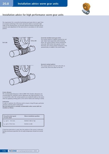
Exit side<br />
Centre distance<br />
The recommended allowance is ISA J7 (DIN 7161). Smaller allowances are<br />
recommended for multistart worms. Maximum axis angle deviation is not<br />
to exceed 40» to 60». The contact patterns are rendered visible on the worm<br />
wheel by applying scribing paint to the worm’s flanks and rotating it slowly.<br />
Lubrication<br />
In order to optimize the efficiency and to ensure a long life span, particular<br />
attention must be paid to lubrication.<br />
Dip feed lubrication is normally recommended, where worm shaft are<br />
installed as follows:<br />
Circumferential speed Worm installation position<br />
of worm shaft<br />
v 1 up to 5 m / sec. bottom / side or top<br />
v 1 up to 10 m / sec. bottom or side<br />
If injection lubrication is used, then the position of the worm is irrelevant.<br />
During continuous operation the oil sump temperature should not exceed<br />
80°C.<br />
© by <strong>Nozag</strong> Switzerland - 2009<br />
© by <strong>Nozag</strong> Switzerland - 2009<br />
Entry side<br />
Correctly installed worm gear drive<br />
The contact pattern is slightly towards the exit<br />
side. Under load respectively while shacking<br />
down, the contact pattern moves towards the<br />
entry side. With drives that operate in both<br />
directions, the contact pattern should be in the<br />
symmetrically in middle of the teeth flanks.<br />
Incorrect contact pattern<br />
The contact pattern is too far to the left, to<br />
correct this, move the wheel to the left.