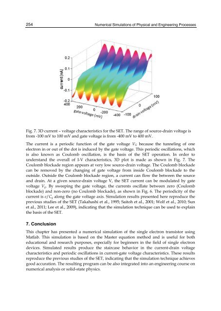
254 <strong>Numerical</strong> <strong>Simulation</strong>s of Physical and Eng<strong>in</strong>eer<strong>in</strong>g Processes Fig. 7. 3D current – voltage characteristics for the SET. The range of source-dra<strong>in</strong> voltage is from -100 mV to 100 mV and gate voltage is from -400 mV to 400 mV. The current is a periodic function of the gate voltage VG because the tunnel<strong>in</strong>g of one electron <strong>in</strong> or out of the dot is <strong>in</strong>duced by the gate voltage. This periodic oscillations, which is also known as Coulomb oscillation, is the basis of the SET operation. In order to understand the overall of I-V characteristics, 3D plot is made as shown <strong>in</strong> Fig. 7. The Coulomb blockade region appears at very low source-dra<strong>in</strong> voltage. The Coulomb blockade can be removed by the chang<strong>in</strong>g of gate voltage from <strong>in</strong>side Coulomb blockade to the outside. Outside the Coulomb blockade region, a current can flow the between the source and dra<strong>in</strong>. At a given source-dra<strong>in</strong> voltage V, the SET current can be modulated by gate voltage Vg. By sweep<strong>in</strong>g the gate voltage, the currents oscillate between zero (Coulomb blockade) and non-zero (no Coulomb blockade), as shown <strong>in</strong> Fig. 6. The periodicity of the current is e/Cg along the gate voltage axis. <strong>Simulation</strong> results presented here reproduce the previous studies of the SET (Takahashi et al., 1995; Saitoh et al., 2001; Wolf et al., 2010; Sun et al., 2011; Lee et al., 2009), <strong>in</strong>dicat<strong>in</strong>g that the simulation technique can be used to expla<strong>in</strong> the basis of the SET. 7. Conclusion This chapter has presented a numerical simulation of the s<strong>in</strong>gle electron transistor us<strong>in</strong>g Matlab. This simulation is based on the <strong>Master</strong> equation method and is useful for both educational and research purposes, especially for beg<strong>in</strong>ners <strong>in</strong> the field of s<strong>in</strong>gle electron devices. Simulated results produce the staircase behavior <strong>in</strong> the current-dra<strong>in</strong> voltage characteristics and periodic oscillations <strong>in</strong> current-gate voltage characteristics. These results reproduce the previous studies of the SET, <strong>in</strong>dicat<strong>in</strong>g that the simulation technique achieves good accuration. The result<strong>in</strong>g program can be also <strong>in</strong>tegrated <strong>in</strong>to an eng<strong>in</strong>eer<strong>in</strong>g course on numerical analysis or solid-state physics.
<strong>Master</strong> <strong>Equation</strong> - <strong>Based</strong> <strong>Numerical</strong> <strong>Simulation</strong> <strong>in</strong> a S<strong>in</strong>gle <strong>Electron</strong> Transistor Us<strong>in</strong>g Matlab 255 8. References Amman, M.; Wilk<strong>in</strong>s, R.; Ben-Jacob, E.; Maker, P.D.; & Jaklevic, R.C. (1991). Analytic solution for the current-voltage characteristic of two mesoscopic tunnel junctions coupled <strong>in</strong> series, Phys. Rev. B, 43, pp. 1146-1149. Aver<strong>in</strong>, D.V. & Likharev, K.K. (1991). Mesoscopic phenomena <strong>in</strong> Solids, edited by B.L. Altshuler, P.A. Lee, and R.A. Webb (Elsevier, Amsterdam), pp. 173-271. Fonseca, L.R.C.: Korotkov, A.N.: Likharev, K.K.; & Od<strong>in</strong>tsov, A.A. (1997). A numerical study of the dynamics and statistics of s<strong>in</strong>gle electron systems, J. Appl. Phys. 78 (5), pp. 3238- 3251. Hanna, A.E. & T<strong>in</strong>kham, M. (1991). Variation of the Coulomb staircase <strong>in</strong> a two-junction system by fractional electron charge, Phys. Rev. B, 44, pp. 5919-5922. Kirihara, M.; Kuwamura, N.; Taniguchi, K.; & Hamaguchi, C. (1994). Monte Carlo study of s<strong>in</strong>gle-electronic devices, Proceed<strong>in</strong>gs of the International Conference on Solid State Devices and Materials, Yokohama, Japan, pp. 328-330. Likharev, K.K. (1988). Correlated discrete transfer of s<strong>in</strong>gle electrons <strong>in</strong> ultrasmall junctions, IBM J. Res. Develop. 32(1), pp. 144-157. Likharev, K.K. (1999). S<strong>in</strong>gle-electron devices and their applications, Proceed<strong>in</strong>gs of the IEEE, 87, pp. 606-632. Lee, D.S.; Yang, H.S.; Kang, K.C.; Lee, J.E.; Lee, J.H.; Park, S.H.; & Park, B.G. (2009). Silicon- <strong>Based</strong> Dual-Gate S<strong>in</strong>gle-<strong>Electron</strong> Transistors for Logic Applications”, Jpn. J. Appl. Phys. 48, p. 071203. Moraru, D.; Yokoi, K.; Nakamura, R.; Mizuno, T.; & Tabe, M. (2011). Tunable s<strong>in</strong>gle-electron turnstile us<strong>in</strong>g discrete dopants <strong>in</strong> nanoscale SOI-FETs, Key Eng<strong>in</strong>eer<strong>in</strong>g Materials, 470, pp. 27-32. Nuryadi, R.; Ikeda, H.; Ishikawa, Y.; & Tabe, M. (2003). Ambipolar coulomb blockade characteristics <strong>in</strong> a two-dimensional Si multidot device, IEEE Trans. Nanotechnol. 2, pp. 231-235. Nuryadi, R.; Ikeda, H.; Ishikawa, Y.; & Tabe, M. (2005). Current fluctuation <strong>in</strong> s<strong>in</strong>gle- hole transport through a two-dimensional Si multidot, Appl. Phys. Lett., 86, p. 133106. Nuryadi, R.: & Haryono, A. (2010). <strong>Numerical</strong> simulation of s<strong>in</strong>gle electron transistor us<strong>in</strong>g master equation, Proc. SPIE (Southeast Asian International Advances <strong>in</strong> Micro/Nanotechnology), Vol. 7743, p. 77430L. Ono, Y.; & Takahashi, Y. (2003). <strong>Electron</strong> pump by a comb<strong>in</strong>ed s<strong>in</strong>gle-electron/field-effecttransistor structure, Appl. Phys. Lett., 82 (8), pp. 1221–1223. Saitoh, M.; Saito, T.; Inukai, T.; & Hiramoto, T. (2001). Transport spectroscopy of the ultrasmall silicon quantum dot <strong>in</strong> a s<strong>in</strong>gle-electron transistor, Appl. Phys. Lett., Vol. 79, No. 13, pp. 2025 - 2027. Sun, Y.; Rusli & S<strong>in</strong>gh, N. (2011). Room-Temperature Operation of Silicon S<strong>in</strong>gle-<strong>Electron</strong> Transistor Fabricated Us<strong>in</strong>g Optical Lithography, IEEE Trans. Nanotechnology, 10(1), pp. 96-98. Takahashi, Y.; Nagase, M.; Namatsu, H.; Kurihara, K.; Iwadate, K.; Nakajima, Y.; Horiguchi, S.; Murase, K. & Tabe, M. (1995). Fabrication technique Si s<strong>in</strong>gle electron transistor operat<strong>in</strong>g at room temperature, <strong>Electron</strong>. Lett., Vol. 31, No. 2, pp. 136–137. Tucker, J.R. (1992). Complementary digital logic based on the "Coulomb blockade", J. Appl. Phys., 72 (9), pp. 4399-4413.