Master Equation - Based Numerical Simulation in a Single Electron ...
Master Equation - Based Numerical Simulation in a Single Electron ...
Master Equation - Based Numerical Simulation in a Single Electron ...

Create successful ePaper yourself
Turn your PDF publications into a flip-book with our unique Google optimized e-Paper software.
11<br />
<strong>Master</strong> <strong>Equation</strong> - <strong>Based</strong> <strong>Numerical</strong> <strong>Simulation</strong><br />
<strong>in</strong> a S<strong>in</strong>gle <strong>Electron</strong> Transistor Us<strong>in</strong>g Matlab<br />
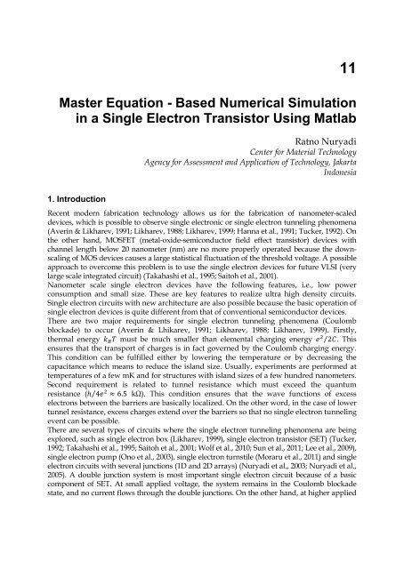
1. Introduction<br />
Ratno Nuryadi<br />
Center for Material Technology<br />
Agency for Assessment and Application of Technology, Jakarta<br />
Indonesia<br />
Recent modern fabrication technology allows us for the fabrication of nanometer-scaled<br />
devices, which is possible to observe s<strong>in</strong>gle electronic or s<strong>in</strong>gle electron tunnel<strong>in</strong>g phenomena<br />
(Aver<strong>in</strong> & Likharev, 1991; Likharev, 1988; Likharev, 1999; Hanna et al., 1991; Tucker, 1992). On<br />
the other hand, MOSFET (metal-oxide-semiconductor field effect transistor) devices with<br />
channel length below 20 nanometer (nm) are no more properly operated because the downscal<strong>in</strong>g<br />
of MOS devices causes a large statistical fluctuation of the threshold voltage. A possible<br />
approach to overcome this problem is to use the s<strong>in</strong>gle electron devices for future VLSI (very<br />
large scale <strong>in</strong>tegrated circuit) (Takahashi et al., 1995; Saitoh et al., 2001).<br />
Nanometer scale s<strong>in</strong>gle electron devices have the follow<strong>in</strong>g features, i.e., low power<br />
consumption and small size. These are key features to realize ultra high density circuits.<br />
S<strong>in</strong>gle electron circuits with new architecture are also possible because the basic operation of<br />
s<strong>in</strong>gle electron devices is quite different from that of conventional semiconductor devices.<br />
There are two major requirements for s<strong>in</strong>gle electron tunnel<strong>in</strong>g phenomena (Coulomb<br />
blockade) to occur (Aver<strong>in</strong> & Lhikarev, 1991; Likharev, 1988; Likharev, 1999). Firstly,<br />
thermal energy must be much smaller than elemental charg<strong>in</strong>g energy ⁄ 2.<br />
This<br />
ensures that the transport of charges is <strong>in</strong> fact governed by the Coulomb charg<strong>in</strong>g energy.<br />
This condition can be fulfilled either by lower<strong>in</strong>g the temperature or by decreas<strong>in</strong>g the<br />
capacitance which means to reduce the island size. Usually, experiments are performed at<br />
temperatures of a few mK and for structures with island sizes of a few hundred nanometers.<br />
Second requirement is related to tunnel resistance which must exceed the quantum<br />
resistance (ℎ 4 ⁄ ≈6.5 kΩ). This condition ensures that the wave functions of excess<br />
electrons between the barriers are basically localized. On the other word, <strong>in</strong> the case of lower<br />
tunnel resistance, excess charges extend over the barriers so that no s<strong>in</strong>gle electron tunnel<strong>in</strong>g<br />
event can be possible.<br />
There are several types of circuits where the s<strong>in</strong>gle electron tunnel<strong>in</strong>g phenomena are be<strong>in</strong>g<br />
explored, such as s<strong>in</strong>gle electron box (Likharev, 1999), s<strong>in</strong>gle electron transistor (SET) (Tucker,<br />
1992; Takahashi et al., 1995; Saitoh et al., 2001; Wolf et al., 2010; Sun et al., 2011; Lee et al., 2009),<br />
s<strong>in</strong>gle electron pump (Ono et al., 2003), s<strong>in</strong>gle electron turnstile (Moraru et al., 2011) and s<strong>in</strong>gle<br />
electron circuits with several junctions (1D and 2D arrays) (Nuryadi et al., 2003; Nuryadi et al.,<br />
2005). A double junction system is most important s<strong>in</strong>gle electron circuit because of a basic<br />
component of SET. At small applied voltage, the system rema<strong>in</strong>s <strong>in</strong> the Coulomb blockade<br />
state, and no current flows through the double junctions. On the other hand, at higher applied
240<br />
<strong>Numerical</strong> <strong>Simulation</strong>s of Physical and Eng<strong>in</strong>eer<strong>in</strong>g Processes<br />
voltage, the Coulomb blockade is defeated and the electrons can tunnel through the junctions<br />
and f<strong>in</strong>ally the current flows. If the island between two tunnel junctions is electrostatically<br />
controlled by the gate capacitance, the system became s<strong>in</strong>gle electron transistor. This device is<br />
rem<strong>in</strong>iscent of a MOSFET, but with a small island (dot) embedded between two tunnel<br />
capacitors/junctions, <strong>in</strong>stead of the usual <strong>in</strong>version channel.<br />
It is well known that a numerical simulation of the devices could help a great deal <strong>in</strong> their<br />
understand<strong>in</strong>g of the devices. However, although so far several groups have reported the<br />
simulation and model<strong>in</strong>g of s<strong>in</strong>gle electron tunnel<strong>in</strong>g devices (Amman et al., 1991; Kirihara et<br />
al., 1994; Fonseca et al., 1997; Wasshuber et al., 1997; Nuryadi et al., 2010), numerical<br />
simulation with detail explanation and easy examples is still needed, especially for beg<strong>in</strong>ners<br />
<strong>in</strong> the field of s<strong>in</strong>gle electron devices. Basically there are two methods to simulate the s<strong>in</strong>gle<br />
electron phenomena, i.e., master equation (Amman et al., 1991; Nuryadi et al., 2010) and<br />
Monte Carlo methods (Kirihara et al., 1994; Fonseca et al., 1997; Wasshuber et al., 1997).<br />
The goal of this chapter is to simulate numerically current-voltage characteristics <strong>in</strong> the<br />
s<strong>in</strong>gle electron transistor based on master equation. A master equation for the probability<br />
distribution of electrons <strong>in</strong> the SET dot (see Fig. 1) is obta<strong>in</strong>ed from the stochastic process,<br />
allow<strong>in</strong>g the calculation of device characteristics. First, I will start with an <strong>in</strong>troduction of<br />
the basic equations <strong>in</strong> <strong>Master</strong> equation (section II). Next, the derivation of free energy<br />
change due to electron tunnel<strong>in</strong>g event is discussed <strong>in</strong> section III. The flowchart of<br />
numerical simulation based on <strong>Master</strong> equation and the Matlab implementation will be<br />
discussed <strong>in</strong> section IV and V, respectively. The examples of simulation resuls are presented<br />
<strong>in</strong> section V. F<strong>in</strong>ally, section VI is conclusion.<br />
2. Basic equations <strong>in</strong> master equation based simulation<br />
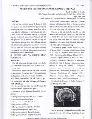
Figure 1 shows the SET circuit consist<strong>in</strong>g of a dot between the source and dra<strong>in</strong> electrodes<br />
separated by tunnel capacitors and . Both tunnel capacitors and have tunnel<br />
resistances and , respectively. The dot is also coupled to the gate electrode with<br />
capacitor <strong>in</strong> order to control the current flow. The total capacitance between the dot and<br />
the outer environment can be writen as , where<br />
= + + . (1)<br />
Fig. 1. S<strong>in</strong>gle electron transistor has a structure of the dot <strong>in</strong> the center coupled by two<br />
tunnel capacitors ( and ) and a gate capacitor . Source is connected to a ground,<br />
where dra<strong>in</strong> and gate are applied by voltages and (Tucker, 1992).
<strong>Master</strong> <strong>Equation</strong> - <strong>Based</strong> <strong>Numerical</strong> <strong>Simulation</strong> <strong>in</strong> a S<strong>in</strong>gle <strong>Electron</strong> Transistor Us<strong>in</strong>g Matlab 241<br />
There are four ma<strong>in</strong> equations for current-voltage characteristics of s<strong>in</strong>gle electron circuits,<br />
i.e., free energy change ∆, tunnel<strong>in</strong>g probability/rate , steady state master equation and<br />
current equation , as follows.<br />
Free energy change:<br />
±<br />
∆ (,) = <br />
<br />
<br />
2 ±(−)∓( +) ± (2a)<br />
±<br />
∆ (,) = <br />
<br />
<br />
2 ∓(−)∓∓ Tunnel<strong>in</strong>g probability/rate:<br />
± () = 1<br />
<br />
± 1<br />
() =<br />
Steady State <strong>Master</strong> equation:<br />
±<br />
−∆ ±<br />
1−∆ ±<br />
−∆ ±<br />
1−∆ (2b)<br />
⁄ (3a)<br />
⁄ (3b)<br />
() () + () =(+1)(+1) + (+1) (4)<br />
Current equation:<br />
<br />
() =∑ () () <br />
− () <br />
=∑ () () <br />
− () (5)<br />
where e is the elemental charge, is the Boltzmann constant, is the temperature, is the<br />
number of electrons <strong>in</strong> the dot, and are a number of electrons flows through the<br />
capacitor and capacitor , respectively, is the background charge and +/- express that<br />
the electron tunnels through the capacitor with the direction from left to the right and from<br />
right to the left, respectively.<br />
<strong>Equation</strong>s (2a) and (2b) are used to calculate the free (electrostatic) energy change ∆ of the<br />
system due to the one electron tunnel<strong>in</strong>g event. It is important to be noted that only tunnel<strong>in</strong>g<br />
events decreas<strong>in</strong>g the electrostatic energy (and dissipat<strong>in</strong>g the difference) are possible.<br />
The values ∆ from equations (2a) and (2b) are used to calculate electron tunnel<strong>in</strong>g<br />
probability <strong>in</strong> the equations (3a) and (3b), respectively. The tunnel<strong>in</strong>g of a s<strong>in</strong>gle electron<br />
through a particular tunnel junction is always a random event, with a certa<strong>in</strong> rate (i.e.,<br />
probability per unit time) which depends solely on the ∆. <strong>Equation</strong> (4) expresses the<br />
<strong>Master</strong> equation <strong>in</strong> steady state, result<strong>in</strong>g the value of (), which is necessary to be used<br />
for the current calculation <strong>in</strong> equation (5).<br />
3. Derivation of free energy change <strong>in</strong> s<strong>in</strong>gle electron transistor circuit<br />
As expla<strong>in</strong>ed above that the free energy change of the system before and after tunnel event<br />
plays a key role on the occurrence of the electron tunnel<strong>in</strong>g, i.e., whether the tunnel<strong>in</strong>g event<br />
occurs or dot. Therefore, the orig<strong>in</strong> of the free energy change <strong>in</strong> SET system is important to<br />
be reviewed. The free energy of voltage-biased s<strong>in</strong>gle electron transistor is def<strong>in</strong>ed by the<br />
difference <strong>in</strong> electrostatic energy stored <strong>in</strong> the circuit (total charg<strong>in</strong>g energy) and work done<br />
by the external voltage source due to tunnel events.
242<br />
<strong>Numerical</strong> <strong>Simulation</strong>s of Physical and Eng<strong>in</strong>eer<strong>in</strong>g Processes<br />
3.1 Total charg<strong>in</strong>g energy<br />
In order to calculate total charg<strong>in</strong>g energy, it is necessary to determ<strong>in</strong>e the voltage applied<br />
on the tunnel capacitor ( ) and tunnel capacitor ( ) us<strong>in</strong>g the follow<strong>in</strong>g step. The<br />
configuration of the charges on each capacitor <strong>in</strong> the s<strong>in</strong>gle-electron transistor circuit<br />
(Figure1) can be expressed as (Tucker, 1992),<br />
= = ( − ), (6a)<br />
= , (6b)<br />
=( −). (6c)<br />
It is noted that the is also subjected to the voltage <strong>in</strong> the dot. Charge <strong>in</strong> the dot is given by,<br />
=− − =−. (7)<br />
Here, =− is a number of electrons <strong>in</strong> the dot.<br />
If the equations (6a), (6b) and (6c) are <strong>in</strong>serted <strong>in</strong>to an equation (7), it can be obta<strong>in</strong>ed the as a function of dra<strong>in</strong> voltage and gate voltage , as follows,<br />
− ( − ) − ( − ) =,<br />
= 1<br />
(<br />
<br />
+ +)<br />
(8)<br />
<br />
From equation (8) and relationship of + =, it can be obta<strong>in</strong>ed the value of voltage on<br />
capacitor , as follows,<br />
=− 1<br />
(<br />
<br />
+ +)<br />
<br />
= 1<br />
( +<br />
<br />
) − −<br />
(9)<br />
<br />
Note that both and are a function of , which is the number of electrons <strong>in</strong> the dot<br />
because of =−. Next, total charg<strong>in</strong>g energy on the SET system can be calculated as follows,<br />
= <br />
+<br />
2 <br />
+<br />
2 <br />
2 = 1<br />
<br />
2<br />
( −) <br />
+ + + <br />
(10)<br />
S<strong>in</strong>ce the values of external power supply and is constant, the effect on electron<br />
tunnel<strong>in</strong>g process only <strong>in</strong>fluences the term of ⁄ 2. 3.2 Work done by external voltage source due to tunnel event<br />
There are two types of tunnel events, i.e., electron tunnels through the capacitor and the<br />
electron tunnels through the capacitor . The amount of the work done by external voltage<br />
source is different from one event to another one. Therefore, the detail explanation of the<br />
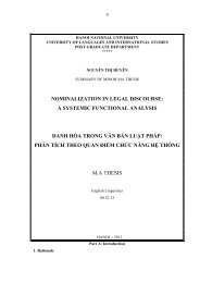
work done for these two types is discussed. Figure 3 shows the charge flow enter/exit from<br />
the voltage source when the electron tunnel through the capacitor (right direction).
<strong>Master</strong> <strong>Equation</strong> - <strong>Based</strong> <strong>Numerical</strong> <strong>Simulation</strong> <strong>in</strong> a S<strong>in</strong>gle <strong>Electron</strong> Transistor Us<strong>in</strong>g Matlab 243<br />
Fig. 3. The charge flow <strong>in</strong> the s<strong>in</strong>gle electron transistor circuit when one electron through the<br />
capacitor (Tucker, 1992).<br />
Work done by the power supply when the electron tunnel through the capacitor is formulated as follows:<br />
1. Change <strong>in</strong> charge when one electron tunnels through capacitor ( ⟶ +)<br />
Change of dot potential due to this electron tunnel<strong>in</strong>g ( ⟶+ or ⟶+1) is<br />
<br />
= − , thus:<br />
= 1<br />
<br />
<br />
+ + ( +)−<br />
<br />
1<br />
(<br />
<br />
+ +)<br />
<br />
= <br />
(11)<br />
<br />
It is noted that and express the values of after and before tunnel<strong>in</strong>g,<br />
respectively.<br />
<br />
Change of charge <strong>in</strong> capacitor is +, where = − . Consider the<br />
equation (6a) it is obta<strong>in</strong>ed the below relationship,<br />
<br />
= − − − ,<br />
=−. (12)<br />
By <strong>in</strong>sert<strong>in</strong>g equation (11) <strong>in</strong>to equation (12), it is obta<strong>in</strong>ed<br />
=− e<br />
Therefore, total change of the charge <strong>in</strong> capacitor is,<br />
+=− e+e<br />
+= + <br />
(13)
244<br />
<strong>Numerical</strong> <strong>Simulation</strong>s of Physical and Eng<strong>in</strong>eer<strong>in</strong>g Processes<br />
<br />
Change of charge <strong>in</strong> capacitor is = − . Consider the equation (6b) <br />
becomes,<br />
<br />
= − ,<br />
= ,<br />
= e<br />
(14)<br />
<br />
Change of charge <strong>in</strong> capacitor is = − . Consider the equation (6c) <br />
becomes,<br />
<br />
= − − − ,<br />
=− ,<br />
=− e<br />
(15)<br />
2. Work done when one electron tunnel through capacitor ( ⟶ +)<br />
Work done by power supply is a sum of multiplication between charge change <strong>in</strong> each<br />
term<strong>in</strong>al and a given power supply voltage. Thus, when one electron tunnel through the<br />
capacitor , the work becomes,<br />
( ) = (+ ) +( ) + ( ) ×0,<br />
( ) = + <br />
<br />
− <br />
<br />
<br />
<br />
The same calculation can be done when the s<strong>in</strong>gle electron tunnel through the capacitor ,<br />
as shown <strong>in</strong> Figure 3.<br />
Fig. 3. The charge flow <strong>in</strong> the s<strong>in</strong>gle electron transistor circuit when an electron tunnels<br />
through the capacitor . 1. Change <strong>in</strong> charge when an electron through the capacitor ( ⟶ +)<br />
Change of potential <strong>in</strong> the dot due to electron tunnel<strong>in</strong>g ( ⟶− or ⟶−1) is<br />
<br />
= − , thus :<br />
(16)
<strong>Master</strong> <strong>Equation</strong> - <strong>Based</strong> <strong>Numerical</strong> <strong>Simulation</strong> <strong>in</strong> a S<strong>in</strong>gle <strong>Electron</strong> Transistor Us<strong>in</strong>g Matlab 245<br />
= <br />
(<br />
+ +(−)) −<br />
<br />
<br />
(<br />
+ +),<br />
<br />
=− <br />
(17)<br />
<br />
<br />
Change <strong>in</strong> charge on a capacitor is = − . Consider the equation (6a),<br />
becomes, <br />
= − − − ,<br />
=− ,<br />
= e<br />
(18)<br />
<br />
<br />
Change <strong>in</strong> the charge on a capacitor is +, where = − . Consider<br />
the equation (6b), becomes, <br />
= − ,<br />
= ( ),<br />
=− e<br />
So the total change <strong>in</strong> charge on the capacitor is,<br />
+=− e+e,<br />
+= + <br />
(19)<br />
<br />
<br />
Changes <strong>in</strong> the charge on a capacitor is = − . Consider equation (6c),<br />
becomes,<br />
<br />
= − − − ,<br />
=− ,<br />
= e<br />
(20)<br />
<br />
2. Work done when one electron through the capacitor ( ⟶ +)<br />
From the above calculation, the work done by the power supply when the electrons tunnels<br />
through the capacitor becomes<br />
( ) = ( )+( ) + (+ ) ×0,<br />
( ) = <br />
<br />
+ <br />
<br />
<br />
<br />
(21)
246<br />
<strong>Numerical</strong> <strong>Simulation</strong>s of Physical and Eng<strong>in</strong>eer<strong>in</strong>g Processes<br />
3.3 Free energy<br />
The most important requirement for the accurence of s<strong>in</strong>gle electron tunnel<strong>in</strong>g is that the total<br />
energy of the transistor system must decrease due to one electron tunnel<strong>in</strong>g. In the other word,<br />
the electron tunnel<strong>in</strong>g will not occur if the total energy of the system <strong>in</strong>creases due to the<br />
electron tunnel<strong>in</strong>g. This condition is called as Coulomb blockade. The free energy is def<strong>in</strong>ed by<br />
the difference <strong>in</strong> the total charg<strong>in</strong>g energy and total work done by the power supply, as follows:<br />
( , ) = <br />
2 <br />
− + <br />
<br />
( , ) = − ,<br />
− <br />
<br />
+ <br />
<br />
+ <br />
<br />
+ (22)<br />
<br />
3.4 Change <strong>in</strong> free energy due to tunnel event<br />
Change <strong>in</strong> free energy after and before electron tunnel<strong>in</strong>g will determ<strong>in</strong>e whether the<br />
electron tunnel<strong>in</strong>g occurs or not. If the system becomes more stable (energy decreases) when<br />
the electron tunnels, electron tunnel<strong>in</strong>g will occur. Let's look at the conditions when the<br />
electron tunnels through the capacitor . The free energy change after and before tunnel<strong>in</strong>g<br />
can be calculated as follows:<br />
∆ ± (, ) = (±)<br />
2 <br />
− <br />
2 <br />
∆ ± (, ) =( ±1, ) −( , ),<br />
−( ±1) + <br />
<br />
− + <br />
<br />
− <br />
<br />
− <br />
<br />
+ <br />
<br />
+ <br />
<br />
+ <br />
<br />
<br />
<br />
+ <br />
<br />
<br />
<br />
±<br />
∆ (,) = <br />
<br />
<br />
2 ±∓( +) ± (23)<br />
By <strong>in</strong>sert<strong>in</strong>g =− <strong>in</strong>to equation (23), the equation (2a) is obta<strong>in</strong>ed.<br />
On the other hand, when the electron tunnels through the capacitor , the free energy<br />
change when the after and before tunnel<strong>in</strong>g is calculated as follows:<br />
∆ ± (, ) = (∓)<br />
2 <br />
∆ ± (, ) =( , ±1) −( , ),<br />
− + <br />
<br />
− <br />
<br />
+( ±1) <br />
<br />
2<br />
Q CG + C2 CG C1CG <br />
<br />
ne 1 V VG ne 2 V VG<br />
2CΣ<br />
CΣ CΣ CΣ CΣ<br />
<br />
− − − + +<br />
<br />
±<br />
∆ (,) = <br />
<br />
<br />
2 ∓∓∓ By <strong>in</strong>sert<strong>in</strong>g Q = Ne− Q0<strong>in</strong>to<br />
equation (24), the equation (2b) is obta<strong>in</strong>ed.<br />
+ <br />
<br />
<br />
<br />
(24)
<strong>Master</strong> <strong>Equation</strong> - <strong>Based</strong> <strong>Numerical</strong> <strong>Simulation</strong> <strong>in</strong> a S<strong>in</strong>gle <strong>Electron</strong> Transistor Us<strong>in</strong>g Matlab 247<br />
4. <strong>Master</strong> equation<br />
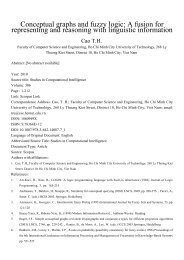
Figure 4 shows the numerical simulation step to calculate IV curve based on <strong>Master</strong><br />
equation method. First, the values of the physical constants (Boltzmann constant<br />
and elemental charge) and device parameters (, , , and ) are def<strong>in</strong>ed. Then,<br />
the external parameters (, , and ) are given. Next, the free energy change of the<br />
system ∆F when the electron tunnels across the tunnel capacitance, is calculated. The ∆<br />
depends on the number of excess electrons <strong>in</strong> the dot, as expressed <strong>in</strong> equations (23)<br />
and (24).<br />
±<br />
∆ (,) = <br />
<br />
<br />
2 ±(−)∓( +) ± (25a)<br />
±<br />
∆ (,) = <br />
<br />
<br />
2 ∓(−)∓∓ (25b)<br />
Us<strong>in</strong>g the values of ∆, s<strong>in</strong>gle electron tunnel<strong>in</strong>g rates across each of two junctions is<br />
determ<strong>in</strong>ed. Each rate depends on both the tunnel<strong>in</strong>g resistance of the junction and the total<br />
energy change of the system due to the tunnel<strong>in</strong>g event. On the other words, for s<strong>in</strong>gle<br />
electron transistor circuit simulation, each electron tunnel<strong>in</strong>g has to be carefully monitored.<br />
The electron tunnel<strong>in</strong>g rate, which is represented by ± , can be easily obta<strong>in</strong>ed from the<br />
basic golden-rule calculation (Aver<strong>in</strong> & Lhikarev, 1991),<br />
± () = 1<br />
<br />
± () = 1<br />
<br />
±<br />
−∆ ±<br />
1−∆ ⁄ <br />
±<br />
−∆ ±<br />
1−∆ ⁄ <br />
(26a)<br />
(26b)<br />
Next, a stochastic process <strong>in</strong> SET circuit is considered. The island charge e will change by the<br />
tunnel<strong>in</strong>g of electrons from or to the island as described by the master equation.<br />
(, )<br />
=(+1)(+1) + (+1) −()() + () (27)<br />
<br />
Here, the dc characteristics is <strong>in</strong>vestigated, therefore the steady state solution of equation<br />
(27) is desired. The steady state master equation is found by sett<strong>in</strong>g the time derivative of<br />
the probability distribution function equal to zero. Therefore, equation (27) becomes (Hanna<br />
et al., 1991)<br />
() () + () =(+1)(+1) + (+1). (28)<br />
In this condition, it is necessary to calculate () for all of possible charge state N. By<br />
<strong>in</strong>sert<strong>in</strong>g from −∞ to ∞ <strong>in</strong>to equation (28), the follow<strong>in</strong>g equations are obta<strong>in</strong>ed.<br />
(−∞) (−∞) + (−∞) =(−∞+1) (−∞ + 1) + (−∞ + 1)<br />
(−1) (−1) + (−1) =(0) (0) + (0)<br />
(0) (0) + (0) =(1) (1) + (1)
248<br />
<strong>Numerical</strong> <strong>Simulation</strong>s of Physical and Eng<strong>in</strong>eer<strong>in</strong>g Processes<br />
(1) (1) + (1) =(1) (2) + (2)<br />
() () + () =(+1) (+1) + (+1)<br />
(∞ − 1) (∞−1) + (∞−1) =(∞) (∞) + (∞) (29)<br />
To solve equations above, the () must satisfy the standard boundary conditions, i.e.<br />
() →0, as →±∞. (30)<br />
Us<strong>in</strong>g this condition, all of the () can be found. However, the () here is not<br />
normalized, so that () requires the normalization as follows:<br />
∑ () =1. (31a)<br />
For this, the follow<strong>in</strong>g transformation is need.<br />
()<br />
() →<br />
∑ ()<br />
F<strong>in</strong>ally, the current can be calculated by,<br />
(31b)<br />
() = ∑ () () <br />
− ().<br />
(32a)<br />
Here, the multiplication of the probability and the difference of rate () − ()<br />
describes the net current flow<strong>in</strong>g through the first junction. In addition, the current may also<br />
expressed <strong>in</strong> the terms of the rates at second junction, as follows.<br />
5. Matlab implementation<br />
() = ∑ () () <br />
− ().<br />
(33b)<br />
The above equations can be easily implemented <strong>in</strong> MATLAB. As expla<strong>in</strong>ed <strong>in</strong> previous<br />
section, the flowchart of numerical simulation is as follows. In the first step, the follow<strong>in</strong>g<br />
physical constant and device parameters are def<strong>in</strong>ed as follows.<br />
% Matlab program source for numerical simulation of <strong>Master</strong> equation<br />
% <strong>in</strong> s<strong>in</strong>gle electron transistor<br />
% This program code is made by Dr. Ratno Nuryadi, Jakarta, Indonesia<br />
clear all;<br />
% Def<strong>in</strong>ition of Physical constant<br />
q=1.602e-19; % electronic charge (C)<br />
kb=1.381e-23; % Boltzman constant (J/K)<br />
% Def<strong>in</strong>ition of Device parameters<br />
c1=1.0e-20; % tunnel capacitor C1 (F)<br />
c2=2.1e-19; % tunnel capacitor C2 (F)<br />
cg=1.0e-18; % gate capacitor Cg (F)<br />
ctotal=c1+c2+cg; % total capacitance (F)<br />
mega=1000000; % def<strong>in</strong>ition of mega=10 6<br />
r1=15*mega; % tunnel resistance R1 (Ohm)<br />
r2=250*mega; % tunnel resistance R2 (Ohm)
<strong>Master</strong> <strong>Equation</strong> - <strong>Based</strong> <strong>Numerical</strong> <strong>Simulation</strong> <strong>in</strong> a S<strong>in</strong>gle <strong>Electron</strong> Transistor Us<strong>in</strong>g Matlab 249<br />
Second, the values of external parameters (, , and ) is given. Here, the , and <br />
are kept a constant while the is varied from Vm<strong>in</strong> to Vmax, as follows:<br />
Vg=0; % gate voltage (V)<br />
q0=0; % background charge q0 is assumed to be zero<br />
temp=10; % temperature T (K)<br />
vm<strong>in</strong>=-0.5; % dra<strong>in</strong> voltage m<strong>in</strong>imum Vm<strong>in</strong> (V)<br />
vmax=0.5; % dra<strong>in</strong> voltage maximum Vmax (V)<br />
NV=1000; % number of grid from Vm<strong>in</strong> to Vmax<br />
dV=(vmax-vm<strong>in</strong>)/NV; % dra<strong>in</strong> voltage <strong>in</strong>crement of each grid po<strong>in</strong>t<br />
for iv=1:NV % loop start for dra<strong>in</strong> voltage<br />
V(iv)=vm<strong>in</strong>+iv*dV; % dra<strong>in</strong> voltage <strong>in</strong> each grid po<strong>in</strong>t<br />
% Note that loop end for dra<strong>in</strong> voltage is located <strong>in</strong> the end of this<br />
program source<br />
Third step is calculation of ∆, as follows:<br />
Nm<strong>in</strong>=-20; % m<strong>in</strong>imum number of N (charge number <strong>in</strong> dot)<br />
Nmax=20; % maximum number of N (charge number <strong>in</strong> dot)<br />
for ne=1:Nmax-Nm<strong>in</strong> % loop start for N<br />
n=Nm<strong>in</strong>+ne; % N charge number <strong>in</strong> dot<br />
% Calculation of ∆ <strong>in</strong> equations (25a) and (25b)<br />
dF1p=q/ctotal*(0.5*q+(n*q-q0)-(c2+cg)*V(iv)+cg*Vg);<br />
dF1n=q/ctotal*(0.5*q-(n*q-q0)+(c2+cg)*V(iv)-cg*Vg);<br />
dF2p=q/ctotal*(0.5*q-(n*q-q0)-c1*V(iv)-cg*Vg);<br />
dF2n=q/ctotal*(0.5*q+(n*q-q0)+c1*V(iv)+cg*Vg);<br />
% Noted that loop end for N is located after calculation of <br />
Forth, the values of ∆ are identified and then used for the calculation of . If ∆ is negative,<br />
will be calculated by equations (26a) and (26b(. However, if the ∆ is positive, is set to<br />
be closed to the zero (very small). Note that the value of is always positive. These<br />
identifications are done for four conditiond of ∆.<br />
if dF1p
250<br />
<strong>Numerical</strong> <strong>Simulation</strong>s of Physical and Eng<strong>in</strong>eer<strong>in</strong>g Processes<br />
if dF2n1e250<br />
p(ne)=1e250;<br />
end<br />
if p(ne)
<strong>Master</strong> <strong>Equation</strong> - <strong>Based</strong> <strong>Numerical</strong> <strong>Simulation</strong> <strong>in</strong> a S<strong>in</strong>gle <strong>Electron</strong> Transistor Us<strong>in</strong>g Matlab 251<br />
ΔΓ 0<br />
Start<br />
1. Def<strong>in</strong>ition of physical parameters<br />
and device parameters<br />
2. Input external parameters (V, V g, Q 0 and T).<br />
Here, V is varied from V m<strong>in</strong> to V max<br />
3. Calculation of ΔF <strong>in</strong> eqs.<br />
(25a) and (25b)<br />
No Yes Calculation of ΔΓ<br />
4. Is ΔF negative?<br />
<strong>in</strong> eqs. (26a) and (26b)<br />
5. Calculation of ρ <strong>in</strong> eq. (28)<br />
6. Normalization ρ <strong>in</strong> eq. (31b)<br />
7. Calculation of current I <strong>in</strong> eq. (33b)<br />
No<br />
8. Is V > V max?<br />
Fig. 4. Flow diagram of the Matlab program used to solve <strong>Master</strong> equation.<br />
Yes<br />
Stop<br />
Plot a graph
252<br />
6. Examples of simulated results<br />
<strong>Numerical</strong> <strong>Simulation</strong>s of Physical and Eng<strong>in</strong>eer<strong>in</strong>g Processes<br />
Two examples will be used to demonstrate the numerical solution of <strong>Master</strong> equation <strong>in</strong><br />
s<strong>in</strong>gle electron transistor.<br />
Example 1:<br />
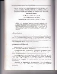
Figures 5(a) dan (b) shows current-dra<strong>in</strong> voltage characteristic of the SET and its dI/dV<br />
curve. The parameter values are C1= 1.0x10⁻²⁰ F, C2= 2.1x10⁻¹⁹ F, CG= 1.0x10⁻¹⁸ F, R1= 15 MΩ<br />
and R2=250 MΩ. The calculation was carried out for an operat<strong>in</strong>g temperature of 10 K, VG= 0<br />
V and Q0= 0. As shown <strong>in</strong> Fig. 5(a), at small source-dra<strong>in</strong> voltage V there is no current,<br />
<strong>in</strong>dicat<strong>in</strong>g the suppression of the current which is known as the Coulomb blockade. In this<br />
region, any tunnel<strong>in</strong>g event would lead to an <strong>in</strong>crease of the total energy and also the<br />
tunnel<strong>in</strong>g rate is exponentially low. There is also evident that the I-V curve has staircase<br />
shape, which is called as Coulomb staircases.<br />
(a) (b)<br />
Fig. 5. (a) The current – dra<strong>in</strong> voltage characteristics for SET and (b) dI/dV curve with the<br />
device parameters are C1= 1.0x10 -20 F, C2= 2.1x10 -19 F, CG= 1.0x10 -18 F, R1= 15 MΩ, R2=250<br />
MΩ and the external parameters are VG= 0 V and T=10 K.<br />
The Coulomb staircase can be understood simply <strong>in</strong> terms of simulation model <strong>in</strong> equation<br />
(28). Initially at dra<strong>in</strong> voltage V=0, we have ρ(N=0)=1, and Γ1 +(N=0)= Γ2 +(N=0)=0. When<br />
V=Vt (Vt is threshold voltage), the rates Γ1 +(N=0) and Γ2 +(N=0) jump sharply allow<strong>in</strong>g charge<br />
to flow through the junction capacitances, so that ρ(n=1)>0. When V=Vt+e/2C∑ there is<br />
jump <strong>in</strong> Γ1 +(N=1) produc<strong>in</strong>g the next another step <strong>in</strong> I-V characteristics. Such steps happen<br />
due to each <strong>in</strong>crease of V by e/2C∑. <strong>Simulation</strong> result <strong>in</strong> Fig. 5 has values of C2>C1 and<br />
R2>R1. Accord<strong>in</strong>g to Fig. 5(b), the width of the steps is ~131 mV, which is determ<strong>in</strong>ed by<br />
e/2C∑.<br />
Example 2:<br />
The current-gate voltage characteristics of SET is plotted <strong>in</strong> Fig. 6. The parameter values are<br />
C1= 4.2x10⁻¹⁹ F, C2= 1.9x10⁻¹⁸ F, CG= 1.3x10⁻¹⁸ F, R1= 150 MΩ, R2=150 MΩ, T=10 K and V= 10<br />
mV. The program source for this I-V curve can be seen below, which is modified from the<br />
previous source.
<strong>Master</strong> <strong>Equation</strong> - <strong>Based</strong> <strong>Numerical</strong> <strong>Simulation</strong> <strong>in</strong> a S<strong>in</strong>gle <strong>Electron</strong> Transistor Us<strong>in</strong>g Matlab 253<br />
V=0.01; % dra<strong>in</strong> voltage (V)<br />
q0=0; % background charge q0 is assumed to be<br />
zero<br />
temp=10; % temperature T (K)<br />
vgm<strong>in</strong>=-0.4; % gate voltage m<strong>in</strong>imum Vm<strong>in</strong> (V)<br />
vgmax=0.4; % gate voltage maximum Vmax (V)<br />
NVg=800; % number of grid from Vgm<strong>in</strong> to Vgmax<br />
dVg=(vgmax-vgm<strong>in</strong>)/NVg; % gate voltage <strong>in</strong>crement of each grid po<strong>in</strong>t<br />
for iv=1:NVg % loop start for gate voltage<br />
Vg(iv)=vgm<strong>in</strong>+iv*dVg; % dra<strong>in</strong> voltage <strong>in</strong> each grid po<strong>in</strong>t<br />
% Note that loop end for dra<strong>in</strong> voltage is located <strong>in</strong> the end of this<br />
program source<br />
Nm<strong>in</strong>=-20; % m<strong>in</strong>imum number of N (charge number <strong>in</strong> dot)<br />
Nmax=20; % maximum number of N (charge number <strong>in</strong><br />
dot)<br />
for ne=1:Nmax-Nm<strong>in</strong> % loop start for N<br />
n=Nm<strong>in</strong>+ne; % N charge number <strong>in</strong> dot<br />
% Calculation of ∆ <strong>in</strong> equations (25a) and (25b)<br />
dF1p=q/ctotal*(0.5*q+(n*q-q0)-(c2+cg)*V+cg*Vg(iv));<br />
dF1n=q/ctotal*(0.5*q-(n*q-q0)+(c2+cg)*V-cg*Vg(iv));<br />
dF2p=q/ctotal*(0.5*q-(n*q-q0)-c1*V-cg*Vg(iv));<br />
dF2n=q/ctotal*(0.5*q+(n*q-q0)+c1*V+cg*Vg(iv));<br />
% Noted that loop end for N is located after calculation of <br />
Fig. 6. The current – gate voltage characteristics for SET with the parameter values are C1=<br />
4.2x10 -19 F, C2= 1.9x10 -18 F, CG= 1.3x10 -18 F, R1= 150 MΩ, R2=150 MΩ and T=10 K.The dra<strong>in</strong><br />
voltage is 10 mV.
254<br />
<strong>Numerical</strong> <strong>Simulation</strong>s of Physical and Eng<strong>in</strong>eer<strong>in</strong>g Processes<br />
Fig. 7. 3D current – voltage characteristics for the SET. The range of source-dra<strong>in</strong> voltage is<br />
from -100 mV to 100 mV and gate voltage is from -400 mV to 400 mV.<br />
The current is a periodic function of the gate voltage VG because the tunnel<strong>in</strong>g of one<br />
electron <strong>in</strong> or out of the dot is <strong>in</strong>duced by the gate voltage. This periodic oscillations, which<br />
is also known as Coulomb oscillation, is the basis of the SET operation. In order to<br />
understand the overall of I-V characteristics, 3D plot is made as shown <strong>in</strong> Fig. 7. The<br />
Coulomb blockade region appears at very low source-dra<strong>in</strong> voltage. The Coulomb blockade<br />
can be removed by the chang<strong>in</strong>g of gate voltage from <strong>in</strong>side Coulomb blockade to the<br />
outside. Outside the Coulomb blockade region, a current can flow the between the source<br />
and dra<strong>in</strong>. At a given source-dra<strong>in</strong> voltage V, the SET current can be modulated by gate<br />
voltage Vg. By sweep<strong>in</strong>g the gate voltage, the currents oscillate between zero (Coulomb<br />
blockade) and non-zero (no Coulomb blockade), as shown <strong>in</strong> Fig. 6. The periodicity of the<br />
current is e/Cg along the gate voltage axis. <strong>Simulation</strong> results presented here reproduce the<br />
previous studies of the SET (Takahashi et al., 1995; Saitoh et al., 2001; Wolf et al., 2010; Sun<br />
et al., 2011; Lee et al., 2009), <strong>in</strong>dicat<strong>in</strong>g that the simulation technique can be used to expla<strong>in</strong><br />
the basis of the SET.<br />
7. Conclusion<br />
This chapter has presented a numerical simulation of the s<strong>in</strong>gle electron transistor us<strong>in</strong>g<br />
Matlab. This simulation is based on the <strong>Master</strong> equation method and is useful for both<br />
educational and research purposes, especially for beg<strong>in</strong>ners <strong>in</strong> the field of s<strong>in</strong>gle electron<br />
devices. Simulated results produce the staircase behavior <strong>in</strong> the current-dra<strong>in</strong> voltage<br />
characteristics and periodic oscillations <strong>in</strong> current-gate voltage characteristics. These results<br />
reproduce the previous studies of the SET, <strong>in</strong>dicat<strong>in</strong>g that the simulation technique achieves<br />
good accuration. The result<strong>in</strong>g program can be also <strong>in</strong>tegrated <strong>in</strong>to an eng<strong>in</strong>eer<strong>in</strong>g course on<br />
numerical analysis or solid-state physics.
<strong>Master</strong> <strong>Equation</strong> - <strong>Based</strong> <strong>Numerical</strong> <strong>Simulation</strong> <strong>in</strong> a S<strong>in</strong>gle <strong>Electron</strong> Transistor Us<strong>in</strong>g Matlab 255<br />
8. References<br />
Amman, M.; Wilk<strong>in</strong>s, R.; Ben-Jacob, E.; Maker, P.D.; & Jaklevic, R.C. (1991). Analytic<br />
solution for the current-voltage characteristic of two mesoscopic tunnel junctions<br />
coupled <strong>in</strong> series, Phys. Rev. B, 43, pp. 1146-1149.<br />
Aver<strong>in</strong>, D.V. & Likharev, K.K. (1991). Mesoscopic phenomena <strong>in</strong> Solids, edited by B.L.<br />
Altshuler, P.A. Lee, and R.A. Webb (Elsevier, Amsterdam), pp. 173-271.<br />
Fonseca, L.R.C.: Korotkov, A.N.: Likharev, K.K.; & Od<strong>in</strong>tsov, A.A. (1997). A numerical study of<br />
the dynamics and statistics of s<strong>in</strong>gle electron systems, J. Appl. Phys. 78 (5), pp. 3238-<br />
3251.<br />
Hanna, A.E. & T<strong>in</strong>kham, M. (1991). Variation of the Coulomb staircase <strong>in</strong> a two-junction<br />
system by fractional electron charge, Phys. Rev. B, 44, pp. 5919-5922.<br />
Kirihara, M.; Kuwamura, N.; Taniguchi, K.; & Hamaguchi, C. (1994). Monte Carlo study of<br />
s<strong>in</strong>gle-electronic devices, Proceed<strong>in</strong>gs of the International Conference on Solid State<br />
Devices and Materials, Yokohama, Japan, pp. 328-330.<br />
Likharev, K.K. (1988). Correlated discrete transfer of s<strong>in</strong>gle electrons <strong>in</strong> ultrasmall junctions,<br />
IBM J. Res. Develop. 32(1), pp. 144-157.<br />
Likharev, K.K. (1999). S<strong>in</strong>gle-electron devices and their applications, Proceed<strong>in</strong>gs of the IEEE,<br />
87, pp. 606-632.<br />
Lee, D.S.; Yang, H.S.; Kang, K.C.; Lee, J.E.; Lee, J.H.; Park, S.H.; & Park, B.G. (2009). Silicon-<br />
<strong>Based</strong> Dual-Gate S<strong>in</strong>gle-<strong>Electron</strong> Transistors for Logic Applications”, Jpn. J. Appl.<br />
Phys. 48, p. 071203.<br />
Moraru, D.; Yokoi, K.; Nakamura, R.; Mizuno, T.; & Tabe, M. (2011). Tunable s<strong>in</strong>gle-electron<br />
turnstile us<strong>in</strong>g discrete dopants <strong>in</strong> nanoscale SOI-FETs, Key Eng<strong>in</strong>eer<strong>in</strong>g Materials,<br />
470, pp. 27-32.<br />
Nuryadi, R.; Ikeda, H.; Ishikawa, Y.; & Tabe, M. (2003). Ambipolar coulomb blockade characteristics<br />
<strong>in</strong> a two-dimensional Si multidot device, IEEE Trans. Nanotechnol. 2, pp. 231-235.<br />
Nuryadi, R.; Ikeda, H.; Ishikawa, Y.; & Tabe, M. (2005). Current fluctuation <strong>in</strong> s<strong>in</strong>gle-<br />
hole transport through a two-dimensional Si multidot, Appl. Phys. Lett., 86, p.<br />
133106.<br />
Nuryadi, R.: & Haryono, A. (2010). <strong>Numerical</strong> simulation of s<strong>in</strong>gle electron transistor us<strong>in</strong>g<br />
master equation, Proc. SPIE (Southeast Asian International Advances <strong>in</strong><br />
Micro/Nanotechnology), Vol. 7743, p. 77430L.<br />
Ono, Y.; & Takahashi, Y. (2003). <strong>Electron</strong> pump by a comb<strong>in</strong>ed s<strong>in</strong>gle-electron/field-effecttransistor<br />
structure, Appl. Phys. Lett., 82 (8), pp. 1221–1223.<br />
Saitoh, M.; Saito, T.; Inukai, T.; & Hiramoto, T. (2001). Transport spectroscopy of the<br />
ultrasmall silicon quantum dot <strong>in</strong> a s<strong>in</strong>gle-electron transistor, Appl. Phys. Lett., Vol.<br />
79, No. 13, pp. 2025 - 2027.<br />
Sun, Y.; Rusli & S<strong>in</strong>gh, N. (2011). Room-Temperature Operation of Silicon S<strong>in</strong>gle-<strong>Electron</strong><br />
Transistor Fabricated Us<strong>in</strong>g Optical Lithography, IEEE Trans. Nanotechnology, 10(1),<br />
pp. 96-98.<br />
Takahashi, Y.; Nagase, M.; Namatsu, H.; Kurihara, K.; Iwadate, K.; Nakajima, Y.; Horiguchi,<br />
S.; Murase, K. & Tabe, M. (1995). Fabrication technique Si s<strong>in</strong>gle electron transistor<br />
operat<strong>in</strong>g at room temperature, <strong>Electron</strong>. Lett., Vol. 31, No. 2, pp. 136–137.<br />
Tucker, J.R. (1992). Complementary digital logic based on the "Coulomb blockade", J. Appl.<br />
Phys., 72 (9), pp. 4399-4413.
256<br />
<strong>Numerical</strong> <strong>Simulation</strong>s of Physical and Eng<strong>in</strong>eer<strong>in</strong>g Processes<br />
Wasshuber, C.; Kos<strong>in</strong>a, H.; & Selberherr, S. (1997). SIMON-A simulator for s<strong>in</strong>gle-electron<br />
tunnel devices and circuits, IEEE Transactions on Computer-Aided Design of Integrated<br />
Circuits and Systems, 16 (9), pp. 937 – 944.<br />
Wolf, C.R.; Thonke, K.; & Sauer, R. (2010). S<strong>in</strong>gle-electron transistors based on selfassembled<br />
silicon-on-<strong>in</strong>sulator quantum dots, Appl. Phys. Lett. 96, p. 142108.