1 - Miller Electric
1 - Miller Electric
1 - Miller Electric

Create successful ePaper yourself
Turn your PDF publications into a flip-book with our unique Google optimized e-Paper software.
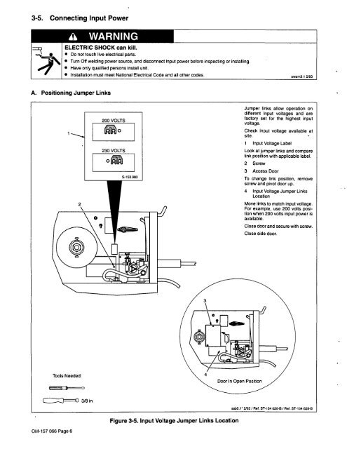
3-5. Connecting Input Power<br />
a WARNING<br />
ELECTRIC SHOCK can kill.<br />
Do not touch live electrical parts.<br />
Turn Off welding power source, and disconnect input power before inspecting or installing.<br />
Have only qualified persons install unit.<br />
A. Positioning Jumper Links<br />
~ 3/8 in<br />
Installation must meet National <strong>Electric</strong>al Code and all other codes.<br />
2<br />
Tools Needed:<br />
OM-157 066 Page 6<br />
200 VOLTS<br />
230 VOLTS<br />
S-153 980<br />
Figure 3-5. Input Voltage Jumper Links Location<br />
Jumper links allow operation on<br />
different input voltages and are<br />
factory set for the highest input<br />
voltage.<br />
Check input voltage available at<br />
site.<br />
1 Input Voltage Label<br />
Look at jumper links and compare<br />
link position with applicable label.<br />
2 Screw<br />
3 Access Door<br />
swam3,1 2/93<br />
To change link position, remove<br />
screw and pivot door up.<br />
4 Input Voltage Jumper Links<br />
Location<br />
Move links to match input voltage.<br />
For example, use 200 volts posi<br />
tion when 200 volts input power is<br />
available.<br />
Close door and secure with screw.<br />
Close side door.<br />
ssb5.1 2/92/ Ret. 5T-154 626-B / Ref. 5T-154 628-B