1 - Miller Electric
1 - Miller Electric
1 - Miller Electric

You also want an ePaper? Increase the reach of your titles
YUMPU automatically turns print PDFs into web optimized ePapers that Google loves.
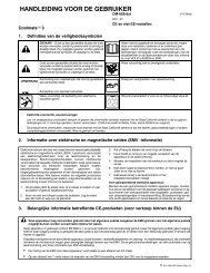
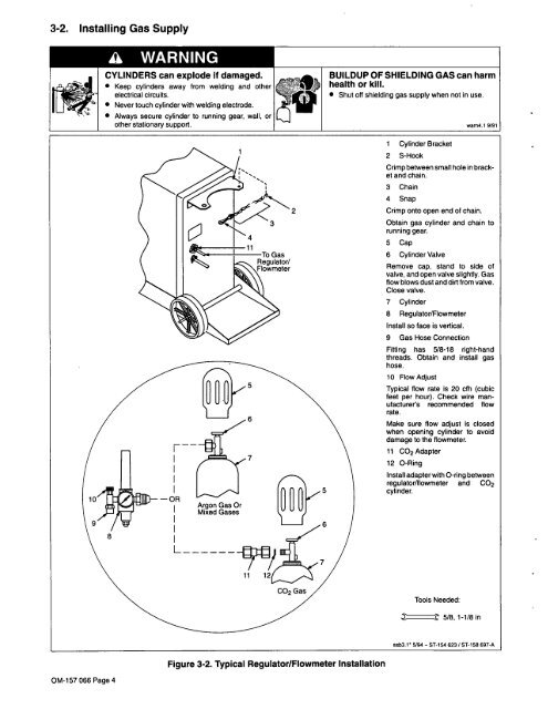
3-2. Installing Gas Supply<br />
OM-157 066 Page 4<br />
a WARNING<br />
CYLINDERS can explode if damaged.<br />
Keep cylinders away from welding and other<br />
electrical circuits.<br />
Never touch cylinder with welding electrode.<br />
Always secure cylinder to running gear, wall, or<br />
other stationary support.<br />
Figure 3-2. Typical Regulator/Flowmeter Installation<br />
BUILDUP OF SHIELDING GAS can harm<br />
health or kill.<br />
Shut oft shielding gas supply when not in use.<br />
1 Cylinder Bracket<br />
2 S-Hook<br />
Crimp between small hole in brack<br />
et and chain.<br />
3 Chain<br />
4 Snap<br />
2 Crimp onto open end of chain.<br />
Obtain gas cylinder and chain to<br />
running gear.<br />
5 Cap<br />
6 Cylinder Valve<br />
Remove cap, stand to side of<br />
valve, and open valve slightly. Gas<br />
flow blows dust and dirt from valve.<br />
Close valve.<br />
7 Cylinder<br />
8 Regulator/Flowmeter<br />
Install so face is vertical.<br />
9 Gas Hose Connection<br />
Fitting has 5/8-18 right-hand<br />
threads. Obtain and install gas<br />
hose.<br />
10 Flow Adjust<br />
Typical flow rate is 20 cfh (cubic<br />
feet per hour). Check wire man<br />
ufacturers recommended flow<br />
rate.<br />
Make sure flow adjust is closed<br />
when opening cylinder to avoid<br />
damage to the flowmeter.<br />
11 CO2 Adapter<br />
12 0-Ring<br />
Install adapter with 0-ring between<br />
regulator/flowmeter and CO2<br />
cylinder.<br />
Tools Needed:<br />
~ 5/8,1-1/8in<br />
wam4.1 9/91<br />
ssb3.r 5/94 ST-154 623 / ST.158 697-A