Netzgeräte NE-104S/NE-105S - Videor
Netzgeräte NE-104S/NE-105S - Videor
Netzgeräte NE-104S/NE-105S - Videor

Create successful ePaper yourself
Turn your PDF publications into a flip-book with our unique Google optimized e-Paper software.
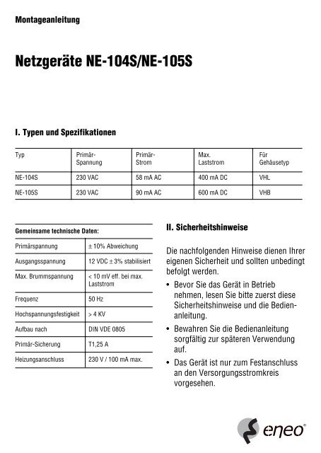
Montageanleitung<br />
<strong>Netzgeräte</strong> <strong>NE</strong>-<strong>104S</strong>/<strong>NE</strong>-<strong>105S</strong><br />
I. Typen und Spezifikationen<br />
Typ Primär- Primär- Max. Für<br />
Spannung Strom Laststrom Gehäusetyp<br />
<strong>NE</strong>-<strong>104S</strong> 230 VAC 58 mA AC 400 mA DC VHL<br />
<strong>NE</strong>-<strong>105S</strong> 230 VAC 90 mA AC 600 mA DC VHB<br />
Gemeinsame technische Daten:<br />
Primärspannung ± 10% Abweichung<br />
Ausgangsspannung 12 VDC ± 3% stabilisiert<br />
Max. Brummspannung < 10 mV eff. bei max.<br />
Laststrom<br />
Frequenz 50 Hz<br />
Hochspannungsfestigkeit > 4 KV<br />
Aufbau nach DIN VDE 0805<br />
Primär-Sicherung T1,25 A<br />
Heizungsanschluss 230 V / 100 mA max.<br />
II. Sicherheitshinweise<br />
Die nachfolgenden Hinweise dienen Ihrer<br />
eigenen Sicherheit und sollten unbedingt<br />
befolgt werden.<br />
• Bevor Sie das Gerät in Betrieb<br />
nehmen, lesen Sie bitte zuerst diese<br />
Sicherheitshinweise und die Bedienanleitung.<br />
• Bewahren Sie die Bedienanleitung<br />
sorgfältig zur späteren Verwendung<br />
auf.<br />
• Das Gerät ist nur zum Festanschluss<br />
an den Versorgungsstromkreis<br />
vorgesehen.
• Anschlussarbeiten sind nur von einer<br />
Fachkraft nach VBG 4 durchzuführen.<br />
• In der Nähe des Gerätes ist eine allpolige,<br />
leicht zugängliche Netz-Trennvorrichtung<br />
mit mindestens 3 mm<br />
Kontaktöffnungsweite zu installieren,<br />
um das Gerät bei Servicearbeiten freischalten<br />
zu können. Die Schutzleiterverbindung<br />
muss nach DIN VDE 0100<br />
entsprechend niederohmig ausgeführt<br />
werden.<br />
• Beim Einbau sind alle Anforderungen<br />
der DIN VDE 0805 zu erfüllen. Die<br />
einzelnen Adern der Versorgungszuleitung<br />
sind mit Adernendhülsen zu<br />
versehen. Die Netzleitung ist im<br />
Gehäuse so zu fixieren, dass keine<br />
Sekundärleitungen berührt werden<br />
können (s. Punkt IV).<br />
a<br />
d<br />
GRI<br />
Gnd<br />
C2<br />
6<br />
+ 12V DC<br />
ICI<br />
HEATER<br />
c<br />
III. Elektrische Anschlüsse<br />
1. Klemme 1 Erdung<br />
Klemme 2 Eingangsspannung<br />
Klemme 3 230 V / 50 Hz<br />
Klemme 4 Brücke durch Schalt-<br />
Klemme 5 thermostat ersetzen<br />
Buchse 6 Heizung (entsprechend<br />
der Eingangsspannung-Netzgerät)<br />
2. Doppelader (a): + 12 VDC (weiß: +)<br />
doppelt isoliert<br />
3. Sicherung (c): T1,25 A<br />
5 4 3 2 1<br />
y L1 N<br />
b<br />
f<br />
e
IV. Mechanischer Einbau<br />
Der Einbau und elektrische Anschluss in<br />
den Wetterschutzgehäusen darf nur von<br />
entsprechend ausgebildetem Fachpersonal,<br />
nach neuesten VDE-Richtlinien<br />
erfolgen.<br />
Bild 1<br />
a<br />
V. Anschluss der Scheibenheizung<br />
h<br />
g<br />
Th1<br />
Zum Anschluss an die Buchse im Netzgerät<br />
sind nur die Heizungen mit einem<br />
Anschlusswert: 110-265V zu verwenden:<br />
VHL-H220 / VHB-H220.<br />
Die Heizung (d) wird an der Stirnseite in<br />
die Kamerawanne geschoben: Am<br />
Kabelende befindet sich ein montierter<br />
2-pol.-Stecker passend zur Buchse (6)<br />
im Netzgerät.<br />
eneo ® ist eine eingetr. Marke der <strong>Videor</strong> Technical E. Hartig GmbH<br />
Vertrieb ausschließlich über den Fachhandel.<br />
VIDEOR TECHNICAL E. Hartig GmbH<br />
Maybachstraße 5 · 63322 Rödermark/Germany<br />
Tel. (0 60 74) 888-0 · Fax. (0 60 74) 888-100<br />
www.eneo-security.com<br />
Einbau in den Gehäuseserien<br />
VHL und VHB<br />
Wie Bild 1 zeigt, wird das Netzgerät in die<br />
Schlitze der Kamerawanne eingeschoben<br />
und mit den vier Schrauben (b) arretiert.<br />
Die untere Isolierplatte darf nicht entfernt<br />
werden.<br />
Die Netzleitung (g) mit ihren Adern für<br />
L1/N/PE ist an den vorbezeichneten<br />
Klemmen 1-3 aufzulegen. Die Erdverbindung<br />
(h) ist am PE-Punkt (e) und die<br />
PE-Leitung vom Gehäusemittelteil am<br />
PE-Punkt (f) zu stecken.<br />
Der Thermostat Th1 (Heizungs-Zubehör)<br />
ist an den Klemmen 4-5 anstelle der<br />
Drahtbrücke aufzulegen. Der alter-<br />
Bild 2<br />
d<br />
nativ zu verwendende<br />
Thermostat Th2 wird auf<br />
der Unterseite des <strong>Netzgeräte</strong>s<br />
befestigt<br />
(s. Bild 2).<br />
Ansicht des <strong>Netzgeräte</strong>s von unten mit<br />
angeschraubtem Thermostat Th2.<br />
# 990498<br />
Änderungen vorbehalten.<br />
© Copyright by VIDEOR TECHNICAL 03/01
Installation Instructions<br />
Power Supply Units <strong>NE</strong>-<strong>104S</strong>/<strong>NE</strong>-<strong>105S</strong><br />
I. Typen und Spezifikationen<br />
Type Input Input Max. For<br />
voltage current load current housing type<br />
<strong>NE</strong>-<strong>104S</strong> 230 VAC 58 mA AC 400 mA DC VHL<br />
<strong>NE</strong>-<strong>105S</strong> 230 VAC 90 mA AC 600 mA DC VHB<br />
Common technical data:<br />
Input voltage +/- 10% deviation<br />
Output voltage 12 VDC +/- 3% stabilized<br />
Max. ripple voltage < 10 mV eff. at max. load<br />
current<br />
Frequency 50 Hz<br />
High voltage endurance > 4 KV<br />
Constructed to DIN VDE 0805<br />
Primary fuse T1.25 A<br />
Heating connection max. 230 V / 100 mA<br />
II. Safety instructions<br />
The following instructions are for your<br />
own safety and must be observed under<br />
all circumstances:<br />
• Read the safety instructions and<br />
operating manual throughly before<br />
connecting the unit.<br />
• Keep the operating manual in a safe<br />
place for later reference.<br />
• The unit is only intended for permanent<br />
connection to the power supply circuit.
• All connection work is to be carried out<br />
by a qualified technician in compliance<br />
with VBG 4.<br />
• An easily accesible all-pole disconnecting<br />
device with 3mm minimum<br />
contact gap width is to be installed<br />
near the unit so that it can be disconnected<br />
for service work. Earthin<br />
must be low-resistance in compliance<br />
with DIN 0100.<br />
• All DIN 0805 requirements must be<br />
met when installing. The individual<br />
wires of the supply cable are to be<br />
fitted with connector sleeves. The<br />
mains cable is to be fastened in the<br />
housing so that it cannot come into<br />
contact with any secondary cables<br />
(see section IV).<br />
a<br />
d<br />
GRI<br />
Gnd<br />
C2<br />
6<br />
+ 12V DC<br />
ICI<br />
HEATER<br />
c<br />
III. Electrical connection<br />
1. Terminal 1 Earth<br />
Terminal 2 Input voltage<br />
Terminal 3 230 V / 50 Hz<br />
Terminal 4 Replace bridge with<br />
control<br />
Terminal 5 Thermostat<br />
Socket 6 Heating (according to<br />
input voltage mains<br />
unit)<br />
2. Twin wire (a): + 12 VDC (white: +)<br />
double insulated<br />
3. Fuse (c): T1.25 A<br />
5 4 3 2 1<br />
y L1 N<br />
b<br />
f<br />
e
IV. Mechanical installation<br />
Installation and electrical connection in<br />
the weatherproofed housing may only be<br />
carried out by appropriately qualified<br />
technicians in compliance with latest<br />
VDE standards.<br />
Figure Bild 1<br />
a<br />
V. Connecting the screen heater<br />
Only heaters VHL-H220 / VHB-H220 for<br />
110-265 V are to be used for connection<br />
to the socket in the mains unit.<br />
The heater (d) is pushed into the front<br />
side of the camera tray: a 2-pole plug is<br />
connected to the end of the cable to<br />
match the socket no. 6 in the mains unit.<br />
eneo ® is a reg. trademark of <strong>Videor</strong> Technical E. Hartig GmbH<br />
VIDEOR TECHNICAL E. Hartig GmbH (U.K. Branch)<br />
Unit 14, Campbell Court · Campbell Road, Bramley, Tadley<br />
GB-Hampshire RG26 5EG<br />
Tel. (0 12 56) 88 02 20 · Fax. (0 12 56) 88 00 89<br />
www.eneo-security.com<br />
h<br />
g<br />
Th1<br />
Installation in the VHL and VHB<br />
housing series<br />
As seen in fig. 1, the mains unit is<br />
pushed into the slot in the camera tray<br />
and fastened into place by four screws<br />
(b). The lower insulation plate has not to<br />
be removed.<br />
The mains cable (g) with its L1/N/PE<br />
wires is to be connected to the marked<br />
terminals 1-3. The earth cable (h) is to<br />
be plugged into the PE-point (e) and the<br />
PE-conductor connected coming from<br />
the housing middle section to the<br />
PE-point (f).<br />
The thermostat Th1 (heating accessory)<br />
is to be connected to the terminals<br />
4-5 instead of the wire<br />
jumper. As an alternative<br />
the thermostat Th2 can<br />
be used, which will be<br />
d<br />
fixed on the bottom (insulation<br />
plate) s. fig. 2.<br />
Figure 2<br />
View of the power supply units from<br />
below with fixed thermostat Th2.<br />
# 990498<br />
Technical changes reserved.<br />
© Copyright by VIDEOR TECHNICAL 03/01<br />
VIDEOR TECHNICAL E. Hartig GmbH<br />
Maybachstraße 5 · 63322 Rödermark/Germany<br />
Tel. (0 60 74) 888-0 · Fax. (0 60 74) 888-100