Guidance for partial face excavation machines - VMT GmbH
Guidance for partial face excavation machines - VMT GmbH
Guidance for partial face excavation machines - VMT GmbH

Create successful ePaper yourself
Turn your PDF publications into a flip-book with our unique Google optimized e-Paper software.
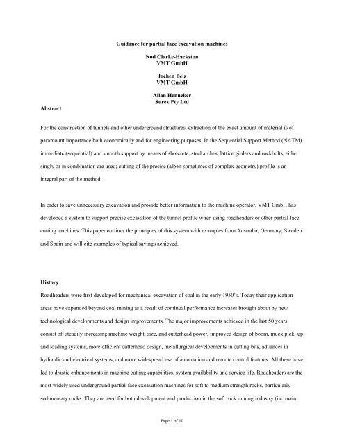
Abstract<br />
<strong>Guidance</strong> <strong>for</strong> <strong>partial</strong> <strong>face</strong> <strong>excavation</strong> <strong>machines</strong><br />
Nod Clarke-Hackston<br />
<strong>VMT</strong> <strong>GmbH</strong><br />
Jochen Belz<br />
<strong>VMT</strong> <strong>GmbH</strong><br />
Allan Henneker<br />
Surex Pty Ltd<br />
For the construction of tunnels and other underground structures, extraction of the exact amount of material is of<br />
paramount importance both economically and <strong>for</strong> engineering purposes. In the Sequential Support Method (NATM)<br />
immediate (sequential) and smooth support by means of shotcrete, steel arches, lattice girders and rockbolts, either<br />
singly or in combination are used; cutting of the precise (albeit sometimes of complex geometry) profile is an<br />
integral part of the method.<br />
In order to save unnecessary <strong>excavation</strong> and provide better in<strong>for</strong>mation to the machine operator, <strong>VMT</strong> <strong>GmbH</strong> has<br />
developed a system to support precise <strong>excavation</strong> of the tunnel profile when using roadheaders or other <strong>partial</strong> <strong>face</strong><br />
cutting <strong>machines</strong>. This paper outlines the principles of this system with examples from Australia, Germany, Sweden<br />
and Spain and will cite examples of typical savings achieved.<br />
History<br />
Roadheaders were first developed <strong>for</strong> mechanical <strong>excavation</strong> of coal in the early 1950’s. Today their application<br />
areas have expanded beyond coal mining as a result of continual per<strong>for</strong>mance increases brought about by new<br />
technological developments and design improvements. The major improvements achieved in the last 50 years<br />
consist of; steadily increasing machine weight, size, and cutterhead power, improved design of boom, muck pick- up<br />
and loading systems, more efficient cutterhead design, metallurgical developments in cutting bits, advances in<br />
hydraulic and electrical systems, and more widespread use of automation and remote control features. All these have<br />
led to drastic enhancements in machine cutting capabilities, system availability and service life. Roadheaders are the<br />
most widely used underground <strong>partial</strong>-<strong>face</strong> <strong>excavation</strong> <strong>machines</strong> <strong>for</strong> soft to medium strength rocks, particularly<br />
sedimentary rocks. They are used <strong>for</strong> both development and production in the soft rock mining industry (i.e. main<br />
Page 1 of 10
haulage drifts, roadways, cross-cuts, etc.) particularly in coal, industrial minerals and evaporate rocks. In civil<br />
construction, they find extensive use <strong>for</strong> <strong>excavation</strong> of tunnels (railway, roadway, sewer, diversion tunnels, etc.) in<br />
soft ground conditions, as well as <strong>for</strong> enlargement and rehabilitation of various underground structures. It is chosen<br />
over other possible tunnelling methods principally because of its application advantages which include free <strong>excavation</strong><br />
area, considerable flexibility in regard to un<strong>for</strong>eseen changes in geological and hydrological conditions, flexibility in terms<br />
of cross-sectional changes, and rapid mobilization with readily available, unsophisticated and relatively inexpensive<br />
<strong>excavation</strong> equipment.<br />
General<br />
All rock and soil has, to a greater or lesser degree, the inherent ability to support itself or stand freely <strong>for</strong> a certain<br />
amount of time. Strong rock can remain free standing <strong>for</strong> hundreds of years while the self-supporting ability of rocks and<br />
soils of weaker types is relatively short-lived and measured in minutes rather than hours, days or years.<br />
For the construction of tunnels and other underground structures, extraction of the exact amount of material is of<br />
paramount importance both economically and <strong>for</strong> engineering purposes. In the Sequential Support Method (NATM)<br />
where immediate (sequential) and smooth support by means of shotcrete, steel arches, lattice girders and rockbolts, either<br />
singly or in combination are used; cutting of the precise (albeit sometimes of complex geometry) profile is an integral part<br />
of the method.<br />
Figure 1 Complex geometrical profiles<br />
Extraction of too much material is costly and can affect the calculations <strong>for</strong> temporary support. Over extraction<br />
also results in the need <strong>for</strong> additional costly material to fill any void between the actually excavated ground and the<br />
Page 2 of 10
designed permanent lining. Under <strong>excavation</strong> necessitates reworking of the area to enable pre<strong>for</strong>med supports to be<br />
erected. The rate of <strong>excavation</strong> also has to be adjusted to the setting rate of the shotcrete.<br />
Figure 2 Precise cutting <strong>for</strong> girder placement Figure 3 Initial shotcrete coating<br />
When using a roadheader one of the main problems affecting the precise cutting of the <strong>face</strong> is visibility of the<br />
cutterhead. Frequently the amount of dust produced, or residual shotcrete in the air, is such that the operator is<br />
unable to see the position of the cutterhead. Marking of the <strong>face</strong> area to be excavated is time consuming <strong>for</strong> the<br />
survey crew and it takes place in an area where stability of the working area is at its potentially most vulnerable.<br />
Even if the machine is positioned correctly and has a limit on the movement of the cutterhead there is a tendency <strong>for</strong><br />
the machine to move as a reaction to the cutting <strong>for</strong>ce applied by the machine.<br />
In order to save this unnecessary <strong>excavation</strong> and provide better in<strong>for</strong>mation to the machine operator, <strong>VMT</strong> <strong>GmbH</strong><br />
has developed a system to support precise <strong>excavation</strong> of the tunnel profile when using roadheaders or other <strong>partial</strong><br />
<strong>face</strong> cutting <strong>machines</strong>.<br />
Figure 4 Poor atmospheric conditions<br />
Page 3 of 10
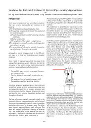
Operating Principle<br />
The operating principle is based on determination of the position and orientation of the body of the roadheader with<br />
respect to a Total Station mounted on the tunnel wall and sighting to two shuttered prisms located on the body of the<br />
machine. Rotation of the body of the machine is monitored by a dual axis inclinometer. Movement of the cutter arm and<br />
the position of the cutterhead itself is determined from sensors (Rotary and Linear encoders) mounted either in or on the<br />
arm. Values from these sensors are taken from the <strong>machines</strong> PLC or by means of direct output from the sensors.<br />
Figure 5 Determination of Cutterhead Position<br />
There are two modes of operation: tracking mode allows fast and continuous distance measurements, lock mode allows<br />
the following of moving prisms. The continuous measurements are only interrupted by directional controls to the back<br />
target. The servo-motorized Total Station - Leica TCA 1203 is mounted on a bracket at the tunnel wall. Every 0.5<br />
seconds the PLC sends data on the horizontal and vertical angles and the length of the cutter arm (kinematics of the road<br />
header). The position of the cutter head is calculated in the road header coordinate system and then trans<strong>for</strong>med into the<br />
global coordinates of the tunnel project. Thus the cutter head position relative to the tunnel axis is known and may be<br />
continuously displayed graphically in the operator cabin, since the tunnel profile is maintained at right angles to the tunnel<br />
axis.<br />
When the theodolite does a directional control check, the tracking mode is switched off and the standard measuring<br />
program is activated. This enables a higher accuracy of distance measurement can be obtained, but it is not possible to<br />
track the target. The average duration of the measurement cycle <strong>for</strong> the directional control is 25 seconds.<br />
The data from the Total Station is transmitted to the <strong>Guidance</strong> PC on the road header via a pair of radio modems, one<br />
mounted next to the Total Station the other mounted on the body of the roadheader.<br />
Page 4 of 10
Sophisticated software enables the project surveyor to easily set the system parameters <strong>for</strong> the machine, enter the Designed<br />
Tunnel Alignment Data (DTA) into the program as well as each of the individual profiles to be excavated. A simple<br />
change in the profile icon enables the machine to rapidly change its <strong>excavation</strong> sequence in line with the project’s<br />
requirements<br />
Equipment<br />
The major components are mounted on the body of the machine itself. These include the Main Industrial PC, remote<br />
display and trackball control devise in the control cab, UPS, Central Box, 2 x Shuttered Prisms, Dual Axis Inclinometer<br />
and Local Radio Modem. Additional components; the Leica TCA 1203 motorized Total Station, the Remote Radio<br />
Modem and the Backsight Target Prism are mounted on the tunnel wall. Power <strong>for</strong> the machine components is supplied<br />
from the machine via a UPS. The Total station and Remote Radio Modem are usually powered from the tunnel lighting<br />
circuit.<br />
The Ruggedized Industrial PC, UPS, Central Box and Dual axis inclinometer are all securely mounted on the body of<br />
the machine in an area that gives the maximum protection to these components. The Shuttered prisms are typically<br />
mounted on the roof of the operators cab to give maximum viewability, however due consideration to the alignment of the<br />
tunnel should be taken into account when choosing these locations and to the sighting of positions <strong>for</strong> the Total Station. A<br />
continuous line of sight between the shuttered prisms and the total station is needed throughout the <strong>excavation</strong> cycle. The<br />
Machine body should be surveyed prior to installation of the shuttered prisms and inclinometer unit so that the main axis<br />
of rotation can be determined, the position of the prisms measured and the inclinometer be correctly zeroed.<br />
Page 5 of 10
Figure 6 System Components<br />
The Shuttered prisms are standard survey prisms enclosed in a protective housing with a motorized protective shutter.<br />
The shutter, activated by the software of the SLS system, is only opened <strong>for</strong> the duration of the angle and distance<br />
measurement to the respective prism. This eliminates confusion of prisms or other reflective objects it also helps to keep<br />
the prism sur<strong>face</strong>s clean. The individual prisms can be connected by a bus system.<br />
A fluid damped dual axis inclinometer <strong>for</strong> determination of inclination of the roadheader. The damping behaviour of the<br />
inclinometer can be adapted to the vibration range of the mounting position, in addition the inclinometer is equipped with<br />
a temperature sensor <strong>for</strong> temperature compensation.<br />
The main computer is a ruggedized industrial PC which is housed in a special Stainless Steel enclosure which is fixed<br />
on anti-vibration mounts between the housing and machine body. The mounting location is chosen to give maximum<br />
protection <strong>for</strong> the unit. A UPS is supplied to maintain the appropriate power to the PC in the event of fluctuating power<br />
Page 6 of 10
eing available from the machine. The PC uses the latest Windows Operating system. A remote display <strong>for</strong> operator is<br />
installed in a prime viewing location in the operators cab. Easy access to functions is via track ball control. A remote USB<br />
connector is available <strong>for</strong> attaching a keyboard <strong>for</strong> initial data entry and <strong>for</strong> memory device attachment.<br />
The Central Box inter<strong>face</strong>s between the various sensors of the system and converts these outputs <strong>for</strong> suitable entry into<br />
the Industrial PC. Control signals from the Industrial PC are also converted <strong>for</strong> transfer to the sensors such as the shuttered<br />
prisms.<br />
Radio Modems are used to connect the components on the machine with those on the tunnel wall as the use of cables in<br />
such a consistently changing working environment would be problematic.<br />
The Local Radio Modem is mounted on the machine and effects Wireless Data Communication between SLS-PC and<br />
Total Station whilst the Remote Radio Modem is mounted next to the Total Station with clear path <strong>for</strong> radio signals.<br />
Wireless reception is controlled by the SLS-software. The Remote Radio Modem receives the data from the Local Unit<br />
and transfers them to the Total Station. In case of power failure it changes automatically into battery mode and sends an<br />
alarm signal to the SLS-PC.<br />
The principle measurement tool <strong>for</strong> the SLS-TM system is a Motorized Leica Total Station Model TCA 1203 with<br />
Automatic Target Recognition (ATR). Automatic fine pointing to the prisms speeds up measurements and improves<br />
productivity. A Standard, round retro-reflective prism is used as a rear backsight target. It is recognised and measured by<br />
the ATR target recognition unit of the Total Station and is used to check the bearing of the Total Station. A comparison<br />
between the Backsight Target and Total Stations’ positions during each measurement cycle is used to give a warning in<br />
case of movement of either outside of any preset limits.<br />
Software<br />
The SLS-TM Roadheader <strong>Guidance</strong> System provides an automated means to minimize operating expenses, while<br />
maximizing the accuracy of cut and minimizing time. This is achieved through use of a highly unique, computer-driven<br />
machine operator’s display screen.<br />
The easy to use Windows software has been carefully configured to make data entry as simple as possible. Initial<br />
setup of the system is implemented through the System Editor data entry pages. Input of the Designed Tunnel Alignment<br />
(DTA) is achieved through the DTA Editor pages where the DTA, in point coordinate table <strong>for</strong>mat can be created from the<br />
Page 7 of 10
principle geometric elements that make up the alignment in both horizontal and Vertical. From the Profile Editor each of<br />
the relevant profiles <strong>for</strong> the project can again be created from the geometric elements that make up the profile.<br />
Where multiple profiles are to be excavated in rotating sequence they can all be stored in the main program. When the<br />
individual profile is to be excavated its profile is simply called up from the profile editor menu. Access to the various user<br />
levels is password protected. Several language options are available as well as Metric and Imperial unit options.<br />
Figure 7 Main operator display<br />
To aid the operator the background of the main graphical display is colour coded to indicate the time interval since the<br />
last valid survey reading. Although the measurement cycle can be set to an interval as short as every 20 seconds there may<br />
be times when a valid reading cannot be made, when this occurs a change in the background colouring is made to the<br />
operators display. The colours <strong>for</strong> the background are:-<br />
1. Within initial time interval Grey<br />
2. Time greater than first preset value Yellow<br />
3. Time greater than second preset level Red<br />
The typical time intervals being 3 minutes and 6 minutes.<br />
A full dialogue of the survey positions is available from the survey position screens.<br />
Developments from original system<br />
Since the basic system was created there has been a constant programme of developments, frequently inspired by the<br />
end users of the equipment.<br />
All in<strong>for</strong>mation that is monitored by the system is saved in the system database. This open plat<strong>for</strong>m enable customized<br />
reporting to be made and a comprehensive package of displays of the excavated sections of the tunnel including 3-D views<br />
and volumetric calculations have been created. This enables comprehensive reporting of the excavated profile to be<br />
Page 8 of 10
created and presented to the owner in a clear concise manner. The full scope of the systems capabilities is still to be fully<br />
realised although its use in providing intermediate “as built” documentation is rapidly gaining popularity with the sites<br />
where the systems is in use.<br />
Figure 8 Profile Viewer – General display Figure 9 Detailed View of section<br />
Extension into excavator and bolter guidance<br />
Having seen the of the guidance control <strong>for</strong> the roadheader on the Eastlink project in Melbourne, Australia, the<br />
site personnel requested a system to be created <strong>for</strong> use on a Caterpillar excavator as the application was very similar<br />
to that of the roadheader. This was quickly and successfully implemented.<br />
A further major concern on this project was <strong>for</strong> the safety of the survey personnel who had to enter the<br />
unsupported <strong>face</strong> area to mark out the positions <strong>for</strong> the drilling of the rockbolt support holes. Finding a way to<br />
accurately position the drill of the bolter without physically marking the sur<strong>face</strong> <strong>for</strong> the various support<br />
classifications was achieved with and adaptation of the roadheader guidance system. Substantial costs savings were<br />
made due to the sequential nature of the use of the roadheader, <strong>for</strong> <strong>excavation</strong> and the Bolter <strong>for</strong> support which<br />
enabled the use of many of the main components of the system including the total station and wireless modems. To<br />
change from one system to the other it is only necessary to switch off the system on one machine and initiating it on<br />
the next machine. The software automatically initiates a survey and calculates the <strong>machines</strong> position and profile<br />
section to be worked upon.<br />
Page 9 of 10
Figure 10 <strong>Guidance</strong> <strong>for</strong> Bolter used in conjunction with Roadheader system<br />
Benefits reported by end users<br />
It has always been difficult to get precise figures from any project whilst production is still taking place, however<br />
the following favourable comments have been received from the site in Bilbao:-<br />
• “The operators like the system; they can cut a better profile faster than when it is done manually”.<br />
• “As it is no longer necessary to mark up the <strong>face</strong> by the surveyors there is a time saving of 1½ hours per day<br />
when the machine is not in a none productive mode”.<br />
• “In one section where detailed records of were kept it was found that the more precise cutting achieved with the<br />
guidance system in use enabled a reduction from 600 m 3 to 423m 3 in the amount of concrete in comparison to<br />
and identical section of tunnel excavated without the guidance system”.<br />
REFERENCES<br />
Copur, H., Ozdemir, L. and Rostami, J., 1998, Roadheader Applications in Mining and Tunneling. Mining<br />
Engineering, Vol. 50, No. 3, March, pp. 38-42<br />
Chittenden, N., Müller H., 2004 New Developments in Automated Tunnel Surveying Systems. Proceedings ITA<br />
World Tunnelling Congress 2004, Singapore<br />
Sauer, G., 1990 Light at the end of the tunnel. Construction Technology International in March 1990.<br />
Smith, M., 2006 Face Drilling. Reference Editions Ltd <strong>for</strong> Atlas Copco Rock Drills AB. 2006 Sweden<br />
White, A., 1993 The Installation of Automated Profile <strong>Guidance</strong> on a Dosco MkIIB Roadheader. Paper Presented at<br />
Meeting of The Institution of Mining Engineers, May 13, 1993, Nottingham<br />
Page 10 of 10