Abu Dhabi Presentation2 - VMT GmbH
Abu Dhabi Presentation2 - VMT GmbH
Abu Dhabi Presentation2 - VMT GmbH

Create successful ePaper yourself
Turn your PDF publications into a flip-book with our unique Google optimized e-Paper software.
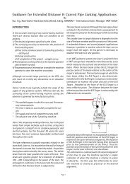
Examining New trends in<br />
Microtunnelling - Automatic<br />
Navigation and Monitoring<br />
Systems For Curved<br />
Microtunnelling<br />
Nod Clarke-Hackston<br />
International Sales Manager<br />
<strong>VMT</strong> <strong>GmbH</strong><br />
Promoting Trenchless Technology in the Middle East<br />
9 th –11 th November 2009, <strong>Abu</strong> <strong>Dhabi</strong>
Complex<br />
Alignments<br />
Navigation<br />
System<br />
System<br />
Description<br />
Extension<br />
Modules<br />
Slide 2<br />
www.vmt-gmbh.de<br />
Geographical Profile - Europipe<br />
project
Complex<br />
Alignments<br />
Navigation<br />
System<br />
System<br />
Description<br />
Extension<br />
Modules<br />
Slide 3<br />
Railway Embankment<br />
(Made Ground)<br />
STW<br />
Site<br />
Horden Pipejack Shaft Option<br />
Lower Cohesive<br />
Glacial Till<br />
(Boulder Clay)<br />
Pipejack 60m Long<br />
diameter 1,5m<br />
Gravity Sewer 350m Long<br />
1m diameter<br />
Upper Cohesive<br />
Glacial Till<br />
(Boulder Clay)<br />
Drop Shaft 6m diameter<br />
45m deep<br />
Existing Ground Level<br />
Top of Cliff<br />
45,2m AOD<br />
Tunnel 150m Long<br />
diameter 2m<br />
Made Ground<br />
(Colliery Spoil)<br />
5m AOD<br />
Middle Magnesian<br />
Limestone<br />
www.vmt-gmbh.de<br />
Agricultural Land S.S.S.I Horden Beach North Sea<br />
Middle Glacial Sands<br />
Middle Magnesian<br />
Limestone<br />
Predicted 60 Year<br />
Erosion Profile<br />
Beach Deposits<br />
Sea Level<br />
Outfall Constructed Using a 150m Long<br />
12m Deep Cofferdam
Complex<br />
Alignments<br />
Navigation<br />
System<br />
System<br />
Description<br />
Extension<br />
Modules<br />
Slide 4<br />
4 No. 300 tonne<br />
Push Cylinders<br />
Horden Curved Pipejack Option<br />
Launch Shaft<br />
IJS 5 IJS 4<br />
Rear Reference<br />
Prism<br />
IJS 3<br />
IJS 2<br />
95m 95m 95m<br />
Tunnel Length 553m<br />
www.vmt-gmbh.de<br />
Vertical Curve r = 1200m<br />
Laser Station<br />
Reference Prisms<br />
IJS 1<br />
Laser Beam<br />
Push-off<br />
Station<br />
TBM<br />
95m 50m 9.3m
Complex<br />
Alignments<br />
Navigation<br />
System<br />
System<br />
Description<br />
Extension<br />
Modules<br />
Slide 5<br />
River Adige Crossing - Italy<br />
www.vmt-gmbh.de<br />
Reception Shaft R. Adige<br />
Launch Shaft<br />
897m
Complex<br />
Alignments<br />
Navigation<br />
System<br />
System<br />
Description<br />
Extension<br />
Modules<br />
Slide 6<br />
Typical Current European<br />
Pipejack Project<br />
www.vmt-gmbh.de
Complex<br />
Alignments<br />
Navigation<br />
System<br />
System<br />
Description<br />
Extension<br />
Modules<br />
Slide 7<br />
Rhine Siphon Tunnel.<br />
Ludwigshaven -Mannheim<br />
744m<br />
Construction Period April - December 1982<br />
www.vmt-gmbh.de
Complex<br />
Alignments<br />
Navigation<br />
System<br />
System<br />
Description<br />
Extension<br />
Modules<br />
Slide 8<br />
www.vmt-gmbh.de<br />
Sewer Outfall:Sayreville NJ - USA
Complex<br />
Alignments<br />
Navigation<br />
System<br />
System<br />
Description<br />
Extension<br />
Modules<br />
Slide 9<br />
Complex curved alignment<br />
pipejacking project<br />
www.vmt-gmbh.de
Complex<br />
Alignments<br />
Navigation<br />
System<br />
System<br />
Description<br />
Extension<br />
Modules<br />
Slide 10<br />
Seo Cho Project–200m Radius<br />
Curve<br />
www.vmt-gmbh.de
Complex<br />
Alignments<br />
Navigation<br />
System<br />
System<br />
Description<br />
Extension<br />
Modules<br />
Slide 11<br />
‘S’ Curve 300m Radius<br />
www.vmt-gmbh.de
Complex<br />
Alignments<br />
Navigation<br />
System<br />
System<br />
Description<br />
Extension<br />
Modules<br />
Slide 12<br />
General Alignment For<br />
Anckelmannplatz Project<br />
www.vmt-gmbh.de
Complex<br />
Alignments<br />
Navigation<br />
System<br />
System<br />
Description<br />
Extension<br />
Modules<br />
Slide 13<br />
Overall Scheme For<br />
Anckelmannplatz Project<br />
www.vmt-gmbh.de
Complex<br />
Alignments<br />
Navigation<br />
System<br />
System<br />
Description<br />
Extension<br />
Modules<br />
Slide 14<br />
Underground<br />
Parking<br />
Start Shaft<br />
Anckelmannplatz Alignment<br />
Total Length 545m<br />
Canal Metro Lines Main Road Underground<br />
Bunker<br />
Interjack Station<br />
Type II<br />
Interjack Station Station<br />
Type II<br />
R = ∞R R=589m = ∞<br />
Interjack Station<br />
Type I<br />
Control Shaft 1 Control Shaft 2<br />
R = 300m<br />
Interjack Station<br />
Type I<br />
R = ∞<br />
Municipal<br />
Building<br />
R = 300m)<br />
www.vmt-gmbh.de<br />
Interjack Station<br />
Type II<br />
Service Shaft<br />
151.43m 44.23m 65.36m 80.5m 14m 116.46m 73.02m<br />
Reception Reception Shaft<br />
R = ∞
Complex<br />
Alignments<br />
Navigation<br />
System<br />
System<br />
Description<br />
Extension<br />
Modules<br />
Slide 15<br />
Anckelmannplatz Proximity To<br />
Existing Sewer<br />
www.vmt-gmbh.de
Complex<br />
Alignments<br />
Navigation<br />
System<br />
System<br />
Description<br />
Extension<br />
Modules<br />
Slide 16<br />
www.vmt-gmbh.de<br />
Anckelmannplatz Parts List For<br />
Pipes
Complex<br />
Alignments<br />
Navigation<br />
System<br />
System<br />
Description<br />
Extension<br />
Modules<br />
Slide 17<br />
www.vmt-gmbh.de<br />
Line & Level and Angular Tolerances<br />
Joint deflection OK<br />
Tolerance Centre Line<br />
Deflection failure<br />
Tolerance Centre Line
Complex<br />
Alignments<br />
Navigation<br />
System<br />
System<br />
Description<br />
Extension<br />
Modules<br />
Slide 18<br />
www.vmt-gmbh.de<br />
Total length of drives guided by <strong>VMT</strong> Pipejacking Guidance systems: - 6/05/2009 = 232,666 m<br />
Distribution of advanced meters according to inside diameters of pipes<br />
Total sum of meters for drives up to ID 1000mm: 7,495 m<br />
Total sum of meters for drives from ID 1000mm up to ID 1200mm: 24,813 m<br />
Total sum of meters for drives from ID 1200mm up to ID 1400mm: 5,965 m<br />
Total sum of meters for drives from ID 1400mm up to ID 1600mm: 36,757 m<br />
Total sum of meters for drives from ID 1600mm up to ID 2000mm: 61,210 m<br />
Total sum of meters for drives from ID 2000mm up to ID 2500mm: 64,384 m<br />
Total sum of meters for drives from ID 2500mm up to ID 3000mm: 31,162 m<br />
Mix Shield TBM<br />
Open Face Shield (excavators, roadheaders ...)<br />
others<br />
Reference List Overview<br />
Total sum of meters for drives over ID 3000mm:<br />
Distribution of advanced meters according to TBM Types<br />
AVN-style TBM<br />
EPB-style TBM<br />
880 m<br />
79,034 m<br />
27,883<br />
10,224<br />
4,460<br />
6,817<br />
m<br />
m<br />
m<br />
m
Complex<br />
Alignments<br />
Navigation<br />
System<br />
System<br />
Description<br />
Extension<br />
Modules<br />
Slide 19<br />
Geology<br />
Requirements on<br />
Navigation Systems<br />
Specification of<br />
the Tender<br />
Type of Machine<br />
Advance Technique<br />
Technical<br />
Requirements<br />
Navigation System<br />
Alignment<br />
Geometry<br />
Economical<br />
Requirements<br />
www.vmt-gmbh.de<br />
Diameter<br />
Customer<br />
Requirements
Complex<br />
Alignments<br />
Navigation<br />
System<br />
System<br />
Description<br />
Extension<br />
Modules<br />
Slide 20<br />
Different Navigation Systems<br />
Navigation Systems can be grouped in different<br />
categories:<br />
Laser-Target Systems<br />
Laser-Total Station-Systems with Active Target<br />
Gyro Systems with Hydro Level<br />
www.vmt-gmbh.de
Complex<br />
Alignments<br />
Navigation<br />
System<br />
System<br />
Description<br />
Extension<br />
Modules<br />
Slide 21<br />
Active<br />
Laser<br />
Target<br />
www.vmt-gmbh.de<br />
The Basic Package contains essential hardware components<br />
System PC including<br />
Navigation Module<br />
SLS-Microtunnelling L<br />
Cabling for 400m<br />
Advance<br />
System Description<br />
Length<br />
Measuring<br />
System<br />
Tunnel Laser<br />
(optional)<br />
Central Communication<br />
Unit
Complex<br />
Alignments<br />
Navigation<br />
System<br />
System<br />
Description<br />
Extension<br />
Modules<br />
Slide 22<br />
The Basic Package with the implementable Navigation<br />
Modules<br />
SLS-Microtunnelling HL<br />
System Description<br />
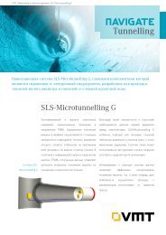
SLS-Microtunnelling G<br />
SLS-<br />
Microtunnelling<br />
Basis Package<br />
www.vmt-gmbh.de<br />
SLS-Microtunnelling LT<br />
SLS-Microtunnelling<br />
LT plus
Complex<br />
Alignments<br />
Navigation<br />
System<br />
System<br />
Description<br />
Extension<br />
Modules<br />
Slide 23<br />
Navigation Systems<br />
SLS-Microtunnelling HL – Hydro level<br />
www.vmt-gmbh.de
Complex<br />
Alignments<br />
Navigation<br />
System<br />
System<br />
Description<br />
Extension<br />
Modules<br />
Slide 24<br />
Navigation Systems<br />
SLS-Microtunnelling L - Laser<br />
www.vmt-gmbh.de
Complex<br />
Alignments<br />
Navigation<br />
System<br />
System<br />
Description<br />
Extension<br />
Modules<br />
Slide 25<br />
Navigation Systems<br />
SLS-Microtunnelling LT – Laser Total Station<br />
www.vmt-gmbh.de
Complex<br />
Alignments<br />
Navigation<br />
System<br />
System<br />
Description<br />
Extension<br />
Modules<br />
Slide 26<br />
Navigation Systems<br />
SLS-Microtunnelling G - Gyro<br />
www.vmt-gmbh.de
Complex<br />
Alignments<br />
Navigation<br />
System<br />
System<br />
Description<br />
Extension<br />
Modules<br />
Slide 27<br />
Navigation Systems<br />
Display of TBM Position<br />
www.vmt-gmbh.de
Complex<br />
Alignments<br />
Navigation<br />
System<br />
System<br />
Description<br />
Extension<br />
Modules<br />
Slide 28<br />
Operating Principle of SLS-LT<br />
www.vmt-gmbh.de<br />
Laser based system working to an active target<br />
Motorized Laser Total Station enables frequent,<br />
automatic measurement cycles to all system points<br />
Basic philosophy at the heart of the SLS-LT system “the<br />
pipes will follow the hole made by the machine”<br />
Position of Laser Station and Backsight Target is<br />
determined in order to the recorded reference line of<br />
pipes<br />
Inclinometers are mounted in the system for roll<br />
correction<br />
Laser Total Station mounted on a self-levelling platform<br />
Periodic control surveys are necessary to replace the<br />
recorded reference line
Complex<br />
Alignments<br />
Navigation<br />
System<br />
System<br />
Description<br />
Extension<br />
Modules<br />
Slide 29<br />
Start Shaft Backsight Target<br />
Target Length<br />
Survey Prism<br />
Measurement<br />
System<br />
Laser Station<br />
SLS-LT Phase 1<br />
TBM<br />
Design Tunnel Axis<br />
Control Cabin<br />
Plan Section<br />
Laser Station<br />
www.vmt-gmbh.de<br />
Target<br />
TBM
Complex<br />
Alignments<br />
Navigation<br />
System<br />
System<br />
Description<br />
Extension<br />
Modules<br />
Slide 30<br />
SLS-LT Phase 2<br />
Start Shaft Backsight Target Left Reference Prism Target Length<br />
Survey Prism<br />
Measurement<br />
System<br />
Laser Station Right Reference Prism TBM Design Tunnel Axis<br />
Laser Station Reference pipe<br />
www.vmt-gmbh.de<br />
Control Cabin<br />
Plan Section<br />
Target<br />
TBM
Complex<br />
Alignments<br />
Navigation<br />
System<br />
System<br />
Description<br />
Extension<br />
Modules<br />
Slide 31<br />
Start Shaft Backsight Target Left Reference Prism Target Length<br />
Survey Prism<br />
Measurement<br />
System<br />
Plan<br />
SLS-LT Phase 3<br />
Section<br />
www.vmt-gmbh.de<br />
Control Cabin<br />
Laser Station Right Reference Prism TBM Design Tunnel Axis<br />
Backsight Target<br />
Survey Prism<br />
Laser Station Reference pipe<br />
Target<br />
TBM
Complex<br />
Alignments<br />
Navigation<br />
System<br />
System<br />
Description<br />
Extension<br />
Modules<br />
Slide 32<br />
Survey Pillar In Shaft<br />
Temporary Protection<br />
for Laser Theodolite<br />
www.vmt-gmbh.de
Complex<br />
Alignments<br />
Navigation<br />
System<br />
System<br />
Description<br />
Extension<br />
Modules<br />
Slide 33<br />
Laser Station in 1800mm Pipe<br />
Vertical<br />
Tunnel Axis<br />
200<br />
532<br />
195<br />
617 592<br />
1068<br />
www.vmt-gmbh.de
Complex<br />
Alignments<br />
Navigation<br />
System<br />
System<br />
Description<br />
Extension<br />
Modules<br />
Slide 34<br />
Total Station Clearance at<br />
Maximum Roll of AD-12<br />
www.vmt-gmbh.de
Complex<br />
Alignments<br />
Navigation<br />
System<br />
System<br />
Description<br />
Extension<br />
Modules<br />
Slide 35<br />
www.vmt-gmbh.de<br />
Various Laser Station mounting<br />
options
Complex<br />
Alignments<br />
Navigation<br />
System<br />
System<br />
Description<br />
Extension<br />
Modules<br />
Slide 36<br />
Guidance System for Diameters<br />
from 800mm to 4.0m<br />
www.vmt-gmbh.de
Complex<br />
Alignments<br />
Navigation<br />
System<br />
System<br />
Description<br />
Extension<br />
Modules<br />
Slide 37<br />
Target Types<br />
www.vmt-gmbh.de
Complex<br />
Alignments<br />
Navigation<br />
System<br />
System<br />
Description<br />
Extension<br />
Modules<br />
Slide 38<br />
ELS Target Support Bracket<br />
www.vmt-gmbh.de<br />
Target Support Bracket
Complex<br />
Alignments<br />
Navigation<br />
System<br />
System<br />
Description<br />
Extension<br />
Modules<br />
Slide 39<br />
Reference Prisms Mounted on<br />
Clamping Ring<br />
Prism<br />
Clamping Ring<br />
Prism<br />
www.vmt-gmbh.de
Complex<br />
Alignments<br />
Navigation<br />
System<br />
System<br />
Description<br />
Extension<br />
Modules<br />
Slide 40<br />
Backsight Prism<br />
Backsight Inclinometer<br />
www.vmt-gmbh.de<br />
Backsight Prism and Inclinometer
Complex<br />
Alignments<br />
Navigation<br />
System<br />
System<br />
Description<br />
Extension<br />
Modules<br />
Slide 41<br />
Measurement Cycle<br />
www.vmt-gmbh.de<br />
1. Read values from LMS to determine chainage of Laser<br />
Station.<br />
2. Read inclinometers values.<br />
3. Point Laser Total Station at the backsight target (BT) and<br />
carry out distance measurement to determine the chainage<br />
of the BT.<br />
4. Point Laser Total Station at left reference target and record<br />
values.<br />
5. Point Laser Total Station at right reference target and<br />
record values.<br />
6. Point Laser Total Station at prism on the ALTU target and<br />
record values.<br />
7. Point Laser Total Station at centre of ALTU target and<br />
record values.<br />
8. Monitor reading of ALTU Target values.<br />
9. Carry out calculations for the co-ordination of the new<br />
reference point and TBM position in ALTU target plane and<br />
cutter head.<br />
10. Save data and values to file.<br />
11. Display new measured and calculated values on operators<br />
display.
Complex<br />
Alignments<br />
Navigation<br />
System<br />
System<br />
Description<br />
Extension<br />
Modules<br />
Slide 42<br />
System Editor<br />
The system editor for entering of the system<br />
parameters<br />
www.vmt-gmbh.de
Complex<br />
Alignments<br />
Navigation<br />
System<br />
System<br />
Description<br />
Extension<br />
Modules<br />
Slide 43<br />
Reference Line Editor<br />
www.vmt-gmbh.de<br />
The Reference Line Editor shows the as-built position of<br />
the pipes
Complex<br />
Alignments<br />
Navigation<br />
System<br />
System<br />
Description<br />
Extension<br />
Modules<br />
Slide 44<br />
3D Model<br />
www.vmt-gmbh.de<br />
3-dimensional display of the as-built situation of the<br />
pipeline
Complex<br />
Alignments<br />
Navigation<br />
System<br />
System<br />
Description<br />
Extension<br />
Modules<br />
Slide 45<br />
2D Position Plan<br />
2-dimensional display of the as-built position in<br />
relation to the surface<br />
www.vmt-gmbh.de
Complex<br />
Alignments<br />
Navigation<br />
System<br />
System<br />
Description<br />
Extension<br />
Modules<br />
Slide 46<br />
Data Viewer<br />
Creates an advance report file<br />
www.vmt-gmbh.de
Complex<br />
Alignments<br />
Navigation<br />
System<br />
System<br />
Description<br />
Extension<br />
Modules<br />
Slide 47<br />
Internet Viewer<br />
www.vmt-gmbh.de<br />
Online Visualization and Remote Control Solutions
Complex<br />
Alignments<br />
Navigation<br />
System<br />
System<br />
Description<br />
Extension<br />
Modules<br />
Slide 48<br />
www.vmt-gmbh.de<br />
Tunnel and Underground<br />
Integrated Software structure<br />
Online Visualization and Remote Control Solutions<br />
separation plant<br />
compression plant<br />
PLC<br />
user<br />
photos<br />
control cabin<br />
manual<br />
input<br />
documents<br />
user<br />
PDA<br />
user<br />
user<br />
TUnIS Server<br />
manual<br />
input<br />
documents<br />
email<br />
SMS<br />
MMS
Complex<br />
Alignments<br />
Navigation<br />
System<br />
System<br />
Description<br />
Extension<br />
Modules<br />
Slide 49<br />
Extension Modules<br />
www.vmt-gmbh.de<br />
The extension modules of <strong>VMT</strong> cover all requirements that appear<br />
more and more in tenders for pipe jacking construction regarding<br />
the documentation and data recording around all advance<br />
processes.<br />
We provide the sensors for the recording, automation, monitoring<br />
and documentation. All extension modules can be integrated in<br />
the system structure and will be recorded together with the data<br />
of the Guidance System.
Complex<br />
Alignments<br />
Navigation<br />
System<br />
System<br />
Description<br />
Extension<br />
Modules<br />
Slide 50<br />
www.vmt-gmbh.de<br />
Extension Module Data Recording<br />
Length encoder and pressure<br />
sensor at the steering<br />
cylinders<br />
Length encoder at the<br />
interjack station
Complex<br />
Alignments<br />
Navigation<br />
System<br />
System<br />
Description<br />
Extension<br />
Modules<br />
Slide 51<br />
www.vmt-gmbh.de<br />
Extension Module Heading Face<br />
Distance<br />
A non-contact distance meter is mounted in the cutting head of<br />
an open face shield and measures continuously the distance to<br />
the heading face. As soon as a pre-defined limit is exceeded a<br />
warning will be shown on the system monitor. The measured<br />
distance will be recorded in a file for documentation.
Complex<br />
Alignments<br />
Navigation<br />
System<br />
System<br />
Description<br />
Extension<br />
Modules<br />
Slide 52<br />
The Inclinometer Chain System INCS determines the vertical<br />
position of the tunnelling machine. An evaluation of the<br />
measuring data such as pitch and roll affords the precise and<br />
continuous determination<br />
This system can be used as an alternative to the electronic<br />
www.vmt-gmbh.de<br />
INCS Inclinometer Chain System<br />
hydrostatic level, as a stand alone system or as an extension of<br />
the electronic hydrostatic level for advance with great variations in<br />
elevation.<br />
Precise and continuous determination of the vertical position<br />
Alternative to the electronic hydrostatic level<br />
After installation it requires no supervision
Complex<br />
Alignments<br />
Navigation<br />
System<br />
System<br />
Description<br />
Extension<br />
Modules<br />
Slide 53<br />
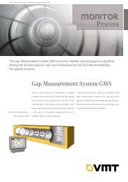
GMS Gap Measurement System<br />
www.vmt-gmbh.de<br />
Gap Measurement System to record the joint gaps of<br />
pipes
Complex<br />
Alignments<br />
Navigation<br />
System<br />
System<br />
Description<br />
Extension<br />
Modules<br />
Slide 54<br />
www.vmt-gmbh.de<br />
AICS Automatic Interjack Control<br />
System<br />
The Automatic Interjack Control System AICS is intelligent<br />
software that coordinates and monitors the opening and closing<br />
of the interjack stations. During the advance, the interjack stations<br />
can be activated individually or as a group.<br />
Automatic interjack control during the advance<br />
Optimize the advance process on long distance drives<br />
Enables the machine to continue the advance independently<br />
of the following pipeline<br />
Assistance for the machine operator
Complex<br />
Alignments<br />
Navigation<br />
System<br />
System<br />
Description<br />
Extension<br />
Modules<br />
Slide 55<br />
MoVi Monitoring Video System<br />
www.vmt-gmbh.de<br />
A desired number of cameras can be placed in various locations in<br />
the pipe line or on the surface to monitor and record interjack<br />
stations, pumps or the separation plant.<br />
The images recorded by the network cameras can be displayed on<br />
the guidance system or on a external monitor and as file with<br />
supplement information such as date, time and positioning.<br />
Real-time visualization of dangerous places on site<br />
Stand Alone System or as integrated version in a <strong>VMT</strong><br />
Navigation System<br />
Optional recording of the images in defined intervals
Complex<br />
Alignments<br />
Navigation<br />
System<br />
System<br />
Description<br />
Extension<br />
Modules<br />
Slide 56<br />
Lubrication with Bentonite<br />
www.vmt-gmbh.de<br />
Filling of the annular gap created by the overcut<br />
Reduction of the friction between pipe and ground<br />
Reduction of jacking forces<br />
Lower stress on jacking pipes<br />
Avoiding of pipe damages<br />
Enables longer drives<br />
Enables curved drives<br />
Successful completion of project
Complex<br />
Alignments<br />
Navigation<br />
System<br />
System<br />
Description<br />
Extension<br />
Modules<br />
Slide 57<br />
Manual Lubrication<br />
www.vmt-gmbh.de<br />
One worker goes frequently through the pipeline and<br />
opens / closes the each valve by hand.<br />
Additional manpower needed: long drives require<br />
one person who is exclusively doing the lubrication<br />
of the pipeline<br />
One complete lubrication cycle takes a relatively<br />
long time<br />
The operator who sees directly the development of<br />
the jacking forces has only limited influence on the<br />
lubrication process<br />
No documentation of bentonite consumption
Complex<br />
Alignments<br />
Navigation<br />
System<br />
System<br />
Description<br />
Extension<br />
Modules<br />
Slide 58<br />
Automatic Lubrication<br />
www.vmt-gmbh.de<br />
PC controlled pneumatic valves open and close automatically. Documentation<br />
of consumption and pressure values.<br />
The automatic procedure enables a continuous and reliable lubrication of the<br />
whole pipeline<br />
Enables shorter lubrication intervals<br />
Faster and more effective lubrication of the pipeline<br />
Operator controls lubrication process himself and can therefore react<br />
immediately to changing jacking forces<br />
The sequence of lubrication can easily be adapted, the lubrication can be<br />
concentrated on critical areas, leaking areas e.g. near interjack stations can<br />
be excluded<br />
Clear and detailed documentation of the whole lubrication process including<br />
consumption and pressure of bentonite as well as assignment to the<br />
separate valves and cycles<br />
No additional manpower necessary for the lubrication of the pipeline<br />
especially in small diameter tunnels access to the tunnel is limited due to<br />
safety regulations
Complex<br />
Alignments<br />
Navigation<br />
System<br />
System<br />
Description<br />
Extension<br />
Modules<br />
Slide 59<br />
Single Valve Lubrication<br />
Ball Valve<br />
Injection Nozzle<br />
Electronic<br />
Valve<br />
Electronic<br />
Valve<br />
Electronic<br />
Valve<br />
www.vmt-gmbh.de<br />
Concrete Pipe<br />
Bentonite Coating<br />
(annular<br />
(annular gap)<br />
gap)<br />
Main Bentonite<br />
Supply line<br />
Ground
Complex<br />
Alignments<br />
Navigation<br />
System<br />
System<br />
Description<br />
Extension<br />
Modules<br />
Slide 60<br />
Ring Lubrication<br />
Ball Valve<br />
Injection Nozzle<br />
Bentonite<br />
Ring Line<br />
Electronic<br />
Valve<br />
www.vmt-gmbh.de<br />
Concrete Pipe<br />
Bentonite Coating<br />
(annular<br />
(annular gap)<br />
gap)<br />
Main Bentonite<br />
Supply line<br />
Ground
Complex<br />
Alignments<br />
Navigation<br />
System<br />
System<br />
Description<br />
Extension<br />
Modules<br />
Slide 61<br />
www.vmt-gmbh.de<br />
ABLS – Description of Hardware
Complex<br />
Alignments<br />
Navigation<br />
System<br />
System<br />
Description<br />
Extension<br />
Modules<br />
Slide 62<br />
www.vmt-gmbh.de<br />
ABLS – Description of Software<br />
Provides continuous and proper lubrication of the tunnel<br />
Display of the already connected valves<br />
Offers different lubrication methods<br />
The user chooses the valves to be integrated in the<br />
lubrication cycle<br />
Lubrication time and max. lubrication pressure can be<br />
defined for each single valve<br />
The software allows the integration of the bentonite pump<br />
itself – start/stop signals will then be given by the software<br />
Data Recording:<br />
consumption / pressure / lubrication time for each valve<br />
total consumption, max. pressures, date, time, chainage
Complex<br />
Alignments<br />
Navigation<br />
System<br />
System<br />
Description<br />
Extension<br />
Modules<br />
Slide 63<br />
www.vmt-gmbh.de<br />
ABLS – Description of Software<br />
Integrated ABLS<br />
The ABLS can easily be integrated to any existing navigation<br />
system SLS-Microtunnelling<br />
Uses the same cables and communication units as the<br />
navigation systems<br />
Software runs on the same PC<br />
Stand-Alone ABLS<br />
The ABLS can also be used independently from any<br />
navigation system<br />
Supports the operator also on short straight drives
Complex<br />
Alignments<br />
Navigation<br />
System<br />
System<br />
Description<br />
Extension<br />
Modules<br />
Slide 64<br />
Partner Valves<br />
ball valve<br />
injection<br />
nozzle<br />
combination of single<br />
valve and partner valve<br />
concrete pipe<br />
www.vmt-gmbh.de<br />
bentonite coating<br />
(annular gap)<br />
ground<br />
main bentonite<br />
supply line
Complex<br />
Alignments<br />
Navigation<br />
System<br />
System<br />
Description<br />
Extension<br />
Modules<br />
Slide 65<br />
Analysis Tool<br />
Graphical display of bentonite consumption per meter<br />
www.vmt-gmbh.de
Complex<br />
Alignments<br />
Navigation<br />
System<br />
System<br />
Description<br />
Extension<br />
Modules<br />
Page 66<br />
www.vmt-gmbh.de<br />
Hydraulic Joint by Jackcontrol ®<br />
Real Time Monitoring System based on the<br />
Hydraulic Joint
Complex<br />
Alignments<br />
Navigation<br />
System<br />
System<br />
Description<br />
Extension<br />
Modules<br />
Page 67<br />
Loading of Pipes during the<br />
Jacking Operation<br />
Three Standard Cases<br />
www.vmt-gmbh.de
Complex<br />
Alignments<br />
Navigation<br />
System<br />
System<br />
Description<br />
Extension<br />
Modules<br />
Page 68<br />
Deformation and Forces<br />
www.vmt-gmbh.de
Complex<br />
Alignments<br />
Navigation<br />
System<br />
System<br />
Description<br />
Extension<br />
Modules<br />
Page 69<br />
The Hydraulic Joint<br />
Idea<br />
Principle of communicating Tubes / vessels:<br />
Fluid pressure p = const.<br />
www.vmt-gmbh.de<br />
Complete Reversibility of the mechanical behavior of<br />
non-compressible fluids<br />
If a (f) = constant e = 0!<br />
(a (f): specific contact area Pipe Face - Packer)
Complex<br />
Alignments<br />
Navigation<br />
System<br />
System<br />
Description<br />
Extension<br />
Modules<br />
Page 70<br />
Compressed Hose Ring<br />
q<br />
=<br />
pπ<br />
⎡<br />
⋅ ⎢d<br />
+<br />
2 ⎣<br />
⎛ −<br />
dp ⎞⎤<br />
( δ − d ) ⋅⎜1<br />
⎟⎥<br />
⎝ 2k<br />
⎠⎦<br />
www.vmt-gmbh.de
Complex<br />
Alignments<br />
Navigation<br />
System<br />
System<br />
Description<br />
Extension<br />
Modules<br />
Page 71<br />
Cracking of the Concrete<br />
www.vmt-gmbh.de
Complex<br />
Alignments<br />
Navigation<br />
System<br />
System<br />
Description<br />
Extension<br />
Modules<br />
Page 72<br />
www.vmt-gmbh.de<br />
Spalling of the Concrete Cover
Complex<br />
Alignments<br />
Navigation<br />
System<br />
System<br />
Description<br />
Extension<br />
Modules<br />
Page 73<br />
Sensor Unit<br />
www.vmt-gmbh.de
Complex<br />
Alignments<br />
Navigation<br />
System<br />
System<br />
Description<br />
Extension<br />
Modules<br />
Page 74<br />
The Hydraulic Joint<br />
www.vmt-gmbh.de
Thank you for your attention<br />
www.vmt-gmbh.de