Datavideo SE-2800 Instruction Manual A4 - Holdan.eu
Datavideo SE-2800 Instruction Manual A4 - Holdan.eu
Datavideo SE-2800 Instruction Manual A4 - Holdan.eu

Create successful ePaper yourself
Turn your PDF publications into a flip-book with our unique Google optimized e-Paper software.
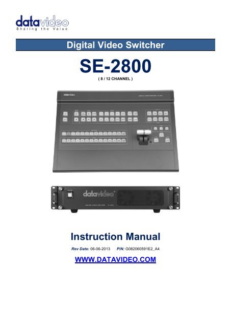
Digital Video Switcher<br />
<strong>SE</strong>-<strong>2800</strong><br />
( 8 / 12 CHANNEL )<br />
<strong>Instruction</strong> <strong>Manual</strong><br />
Rev Date: 06-06-2013 P/N: G082060591E2_<strong>A4</strong><br />
WWW.DATAVIDEO.COM
Contents<br />
Warnings and Precautions ................................................................................................................. 4<br />
Warranty ............................................................................................................................................... 5<br />
Standard Warranty .................................................................................................................... 5<br />
Two Year Warranty ................................................................................................................... 5<br />
Disposal ................................................................................................................................................ 5<br />
Packing List .......................................................................................................................................... 5<br />
Product Overview ................................................................................................................................ 6<br />
Features .................................................................................................................................... 7<br />
Connections & Controls ...................................................................................................................... 8<br />
Control Panel Overview ............................................................................................................ 8<br />
Main Unit - Rear Panel ............................................................................................................. 8<br />
Rear Panel Connections ........................................................................................................... 9<br />
Main Unit – Front Panel ..........................................................................................................10<br />
HDMI Multi-view .................................................................................................................................11<br />
How to change the Multi-view output ......................................................................................11<br />
Keyboard Controls – Video Switching ............................................................................................12<br />
Program and Preset rows .......................................................................................................12<br />
BG ...........................................................................................................................................12<br />
SPEED ....................................................................................................................................12<br />
AUTO TAKE ...........................................................................................................................12<br />
CUT .........................................................................................................................................12<br />
FTB .........................................................................................................................................12<br />
T-Bar .......................................................................................................................................12<br />
Keyboard Controls – Video Transitions ..........................................................................................13<br />
Transition Selection ................................................................................................................13<br />
INV ..........................................................................................................................................13<br />
FIX / A+V ................................................................................................................................13<br />
MIX ..........................................................................................................................................13<br />
FREEZE ..................................................................................................................................13<br />
Transition Confirmation...........................................................................................................13<br />
Keyboard Controls – LOGO 1, LOGO 2, CLOCK and TIMER ........................................................14<br />
LOGO 1...................................................................................................................................14<br />
LOGO 2 or CLOCK .................................................................................................................14<br />
TIMER .....................................................................................................................................14<br />
Keyboard Controls – PIP1, PIP2, DSK1 and DSK2 .........................................................................15<br />
PIP Preset and PIP Program ..................................................................................................15<br />
Assigning a video source input to a PIP .................................................................................15<br />
DSK Preset and DSK Program ...............................................................................................15<br />
Assigning an input to a DSK channel for keying ....................................................................15<br />
Keyboard Controls – Frame Store, AUX and Audio level ..............................................................16<br />
FS – Frame Store Button ........................................................................................................16<br />
How to choose live video input or Frame Store ......................................................................16<br />
AUX Source Selection ............................................................................................................16<br />
Audio Level .............................................................................................................................16<br />
Menu Options .....................................................................................................................................17<br />
<strong>SE</strong>-<strong>2800</strong> Video Layers .......................................................................................................................21<br />
PIP – Picture In Picture function ......................................................................................................22<br />
PIP Settings ............................................................................................................................22<br />
PIP Preset and PIP Program ..................................................................................................22<br />
Assigning a video source input to a PIP .................................................................................22<br />
2
DSK function (CG / LUMA KEY) .......................................................................................................23<br />
DSK Settings ..........................................................................................................................23<br />
DSK Preset and DSK Program ...............................................................................................23<br />
Assigning an input to a DSK channel for keying ....................................................................23<br />
Example <strong>SE</strong>-<strong>2800</strong> and CG-350 Set Up ..................................................................................24<br />
How to obtain software or firmware for the <strong>SE</strong>-<strong>2800</strong> .....................................................................25<br />
Switcher configuration using a computer – <strong>SE</strong>Config software ..................................................25<br />
Switcher tab ............................................................................................................................26<br />
Profiles ....................................................................................................................................26<br />
Settings tab .............................................................................................................................26<br />
Input settings tab ....................................................................................................................26<br />
Multi screen window signs (labels) tab ...................................................................................27<br />
Still pictures (FS) tab ..............................................................................................................27<br />
Logos tab ................................................................................................................................27<br />
Dynamic Logo tab ...................................................................................................................28<br />
Multi screen A tab ...................................................................................................................28<br />
Multi screen B+D tab ..............................................................................................................28<br />
Multi screen C+E tab ..............................................................................................................28<br />
Setting up with the <strong>SE</strong> Remote software .........................................................................................29<br />
<strong>SE</strong>T function ...........................................................................................................................29<br />
Controlling the switcher with a computer – <strong>SE</strong> Remote software ................................................30<br />
Software based Macro functions ............................................................................................30<br />
REC & PLAY functions ...........................................................................................................30<br />
TIME function ..........................................................................................................................30<br />
AUDIO function ..................................................................................................................................31<br />
Overview .................................................................................................................................31<br />
Audio Menu Options – De-embedding SDI or HDMI audio ....................................................31<br />
Audio Menu Options – Monitoring the audio levels ................................................................33<br />
Audio Menu Options – Changing the audio input level ..........................................................33<br />
Changing the audio output level .............................................................................................33<br />
Working with a fixed or single audio source ...........................................................................34<br />
Switching between different embedded audio sources ..........................................................34<br />
GPI / GPO Connections .....................................................................................................................35<br />
<strong>SE</strong>-<strong>2800</strong> Tally Outputs .......................................................................................................................36<br />
How to obtain software or firmware for the <strong>SE</strong>-<strong>2800</strong> .....................................................................37<br />
How to update the <strong>SE</strong>-<strong>2800</strong> Firmware .............................................................................................37<br />
How to Re-calibrate the <strong>SE</strong>-<strong>2800</strong> T-Bar ...........................................................................................40<br />
How to change the <strong>SE</strong>-<strong>2800</strong> video standard ...................................................................................41<br />
Example <strong>SE</strong>-<strong>2800</strong> Set Up ...................................................................................................................44<br />
Dimensions.........................................................................................................................................44<br />
Specifications ....................................................................................................................................45<br />
Service and Support ..........................................................................................................................46<br />
Disclaimer of Product and Services<br />
The information offered in this instruction manual is intended as a guide only. At all times, <strong>Datavideo</strong> Technologies will try to give correct,<br />
complete and suitable information. However, <strong>Datavideo</strong> Technologies cannot exclude that some information in this manual, from time to time,<br />
may not be correct or may be incomplete. This manual may contain typing errors, omissions or incorrect information. <strong>Datavideo</strong> Technologies<br />
always recommend that you double check the information in this document for accuracy before making any purchase decision or using the<br />
product. <strong>Datavideo</strong> Technologies is not responsible for any omissions or errors, or for any subsequent loss or damage caused by using the<br />
information contained within this manual. Further advice on the content of this manual or on the product can be obtained by contacting your<br />
local <strong>Datavideo</strong> Office or dealer.<br />
3
Warnings and Precautions<br />
1. Read all of these warnings and save them for later reference.<br />
2. Follow all warnings and instructions marked on this unit.<br />
3. Unplug this unit from the wall outlet before cleaning. Do not use liquid or aerosol cleaners. Use a damp cloth for<br />
cleaning.<br />
4. Do not use this unit in or near water.<br />
5. Do not place this unit on an unstable cart, stand, or table. The unit may fall, causing serious damage.<br />
6. Slots and openings on the cabinet top, back, and bottom are provided for ventilation. To ensure safe and reliable<br />
operation of this unit, and to protect it from overheating, do not block or cover these openings. Do not place this unit on<br />
a bed, sofa, rug, or similar surface, as the ventilation openings on the bottom of the cabinet will be blocked. This unit<br />
should never be placed near or over a heat register or radiator. This unit should not be placed in a built-in installation<br />
unless proper ventilation is provided.<br />
7. This product should only be operated from the type of power source indicated on the marking label of the AC adapter.<br />
If you are not sure of the type of power available, consult your <strong>Datavideo</strong> dealer or your local power company.<br />
8. Do not allow anything to rest on the power cord. Do not locate this unit where the power cord will be walked on, rolled<br />
over, or otherwise stressed.<br />
9. If an extension cord must be used with this unit, make sure that the total of the ampere ratings on the products plugged<br />
into the extension cord do not exceed the extension cord rating.<br />
10. Make sure that the total amperes of all the units that are plugged into a single wall outlet do not exceed 15 amperes.<br />
11. Never push objects of any kind into this unit through the cabinet ventilation slots, as they may touch dangerous voltage<br />
points or short out parts that could result in risk of fire or electric shock. Never spill liquid of any kind onto or into this<br />
unit.<br />
12. Except as specifically explained elsewhere in this manual, do not attempt to service this product yourself. Opening or<br />
removing covers that are marked “Do Not Remove” may expose you to dangerous voltage points or other risks, and<br />
will void your warranty. Refer all service issues to qualified service personnel.<br />
13. Unplug this product from the wall outlet and refer to qualified service personnel under the following conditions:<br />
a. When the power cord is damaged or frayed;<br />
b. When liquid has spilled into the unit;<br />
c. When the product has been exposed to rain or water;<br />
d. When the product does not operate normally under normal operating conditions. Adjust only those controls<br />
that are covered by the operating instructions in this manual; improper adjustment of other controls may result<br />
in damage to the unit and may often require extensive work by a qualified technician to restore the unit to<br />
normal operation;<br />
e. When the product has been dropped or the cabinet has been damaged;<br />
f. When the product exhibits a distinct change in performance, indicating a need for service.<br />
4
Standard Warranty<br />
Warranty<br />
• <strong>Datavideo</strong> equipment is guaranteed against any manufacturing defects for one year from the date of<br />
purchase.<br />
• The original purchase invoice or other documentary evidence should be supplied at the time of any request<br />
for repair under warranty.<br />
• Damage caused by accident, misuse, unauthorized repairs, sand, grit or water is not covered by this<br />
warranty.<br />
• All mail or transportation costs including insurance are at the expense of the owner.<br />
• All other claims of any nature are not covered.<br />
• Cables & batteries are not covered under warranty.<br />
• Warranty only valid within the country or region of purchase.<br />
• Your statutory rights are not affected.<br />
Two Year Warranty<br />
• All <strong>Datavideo</strong> products purchased after 01-Oct.-2008 qualify for a free one year extension to the standard<br />
Warranty, providing the product is registered with <strong>Datavideo</strong> within 30 days of purchase. For information on<br />
how to register please visit www.datavideo.com or contact your local <strong>Datavideo</strong> office or authorized<br />
Distributors<br />
• Certain parts with limited lifetime expectancy such as LCD Panels, DVD Drives, Hard Drives are only<br />
covered for the first 10,000 hours, or 1 year (whichever comes first).<br />
Any second year warranty claims must be made to your local <strong>Datavideo</strong> office or one of its authorized Distributors<br />
before the extended warranty expires.<br />
Disposal<br />
For EU Customers only - WEEE Marking<br />
This symbol on the product indicates that it should not be treated as household waste. It must<br />
be handed over to the applicable take-back scheme for the recycling of Waste Electrical and<br />
Electronic Equipment. For more detailed information about the recycling of this product, please<br />
contact your local <strong>Datavideo</strong> office.<br />
Packing List<br />
The following items should be included in the box. If any items are missing please contact your supplier.<br />
Item No. Description Quantity<br />
1 <strong>SE</strong>-<strong>2800</strong> Switcher – Main Unit 1<br />
2 <strong>SE</strong>-<strong>2800</strong> Switcher – Control Panel 1<br />
3 Accessory kit * 1<br />
4 <strong>Instruction</strong> <strong>Manual</strong> 1<br />
*The accessory kit also contains a packing list.<br />
5
Product Overview<br />
The <strong>SE</strong>-<strong>2800</strong> is a cost effective HD/SD switcher featuring eight* or twelve channels. Thanks to a 2RU 19” form<br />
factor and 12V DC input the <strong>SE</strong>-<strong>2800</strong> is ideal for use in portable rack units or outside broadcast vehicles. The <strong>SE</strong>-<br />
<strong>2800</strong> produces superb 10 bit 4:2:2 broadcast quality pictures while also offering flexible input and output<br />
configurations. The <strong>SE</strong>-<strong>2800</strong> also has powerful, easy to use effects, such as dual picture in picture (PIP),<br />
downstream keyers (DSK) and logo insertion, as well as a clock and multiple still image frame stores.<br />
The <strong>SE</strong>-<strong>2800</strong> has been designed for live productions such as concerts, conference, sports and worship events as<br />
well as news and studio based programmes that may need to combine a number of video sources with a mixed<br />
audio feed. The unit can also be configured and controlled over an Ethernet network allowing even greater<br />
flexibility and even more user set up options.<br />
That’s <strong>Datavideo</strong>, sharing the value!<br />
*Eight channel units can be upgraded to twelve at a later date<br />
Please speak with your dealer for more information.<br />
6
Features<br />
The twelve input version can be configured as:<br />
Twelve SDI or HD-SDI inputs,<br />
Or Nine SDI or HD-SDI inputs with three HDMI inputs,<br />
Or Six composite inputs, with three SDI inputs and three HDMI inputs<br />
Or Six composite inputs, with six SDI inputs.<br />
The eight input version* can be configured as:<br />
Eight SDI or HD-SDI inputs,<br />
Or Six SDI or HD-SDI inputs with two HDMI inputs,<br />
Or Four composite inputs, with two SDI inputs and two HDMI inputs<br />
Or Four composite inputs, with four SDI inputs.<br />
HDMI based single or dual screen multi-view outputs.<br />
A choice from five set ups, two with optional HDMI Program output.<br />
• Three user defined SDI or HD-SDI outputs.<br />
Each of these outputs has the option to be:<br />
Program output<br />
Or Preview output<br />
Or Program output without logo<br />
Or Program output without logo and DSK overlay<br />
Or Aux output of a selected video input channel (single Aux).<br />
• User defined and positioned dual picture in picture (PIP).<br />
• Easy two step PIP source assignment using keyboard.<br />
• Two downstream keyers (DSK) with a set up choice of basic Luma key or alpha channel.<br />
• Easy two step DSK source assignment using keyboard.<br />
• User choice from seven stored logos for insertion on preview and program outputs.<br />
• One dynamic logo or moving image sequence. File type can be TGA, GIF or AVI up to 75 frames long.<br />
• Frame Store (FS) source for each input channel. User can quickly toggle between a pre-loaded still image<br />
and the connected live source.<br />
• On screen real-time clock featuring HH:MM only – User defined position.<br />
• User defined countdown timer for each input shown within the HDMI Multi-view output.<br />
• Six user defined wipe buttons - choice of 16 wipes with optional border.<br />
• User can define three speed buttons (in frames) for selected transition when using Auto Take button.<br />
• T-Bar can be operated in one way or two way mode.<br />
• Choice of 8 full raster colour backgrounds or SMPTE 75% bars for BG button.<br />
• Up to four channels of audio can be embedded on to the SDI and HDMI Program outputs. Either from an<br />
external audio mixer (not supplied) or selected HDMI, SDI and analogue XLR inputs.<br />
• Audio peak meters displayed on HDMI Multi-view gives confidence of incoming and outgoing audio.<br />
• User choice for synch input and loop through – composite black & burst or HD Tri-Level sync.<br />
• <strong>SE</strong>-<strong>2800</strong> can be configured over an Ethernet network using a supplied Windows 7 PC application.<br />
• <strong>SE</strong>-<strong>2800</strong> can be controlled remotely over an Ethernet network using a supplied Windows 7 PC application.<br />
• Low voltage Bi-colour Tally output on a single 25pin D-sub connector – compatible with other <strong>Datavideo</strong><br />
equipment or bespoke applications.<br />
• GPI - Externally trigger transitions or devices using the 3.5mm jack socket.<br />
• XLR 12V DC input – Makes the unit ideal for studio or OB van based applications.<br />
7
Control Panel Overview<br />
Main Unit - Rear Panel<br />
Connections & Controls<br />
1. Frame Store button 8. Speed Selection<br />
2. Audio Level buttons 9. AUTO TAKE<br />
3. PC / Menu control 10. FTB – Fade To Black<br />
4. Transition selection 11. CUT<br />
5. Logos 1 & 2, Clock & Timer 12. T-Bar – <strong>Manual</strong> Transitions<br />
6. PIP selection PST & PGM 13. Preset Row (PST)<br />
7. DSK selection PST & PGM 14. Program Row (PGM)<br />
1. Input 1 – SD / HD-SDI / CVBS 13. Connect the <strong>SE</strong>-<strong>2800</strong> keyboard here<br />
2. Input 2 – SD / HD-SDI / CVBS 14. External Sync Input<br />
3. Input 3 – SD / HD-SDI 15. User Defined SDI Outputs 1~3<br />
4. Input 4 – SD / HD-SDI / HDMI 16. Sync Output / Ref Loop<br />
5. Input 5 – SD / HD-SDI / CVBS 17. User Defined Multi view Outputs<br />
6. Input 6 – SD / HD-SDI / CVBS 18. Ethernet port for PC control & updates<br />
7. Input 7 – SD / HD-SDI 19. Tally Output connector<br />
8. Input 8 – SD / HD-SDI / HDMI 20. GPI connector<br />
** 9. Input 9 – SD / HD-SDI / CVBS 21. RS-422 connector (not currently used)<br />
** 10. Input10 – SD / HD-SDI / CVBS 22. 4pin XLR Power Input connector<br />
** 11. Input11 – SD / HD-SDI 23. Grounding Terminal<br />
** 12. Input12 – SD / HD-SDI / HDMI 24. 3pin XLR Audio Inputs<br />
25. 3pin XLR Audio Outputs<br />
** Please note inputs 9 to 12 are not present if you have purchased the eight channel <strong>SE</strong>-<strong>2800</strong>.<br />
Eight channel units can be upgraded to twelve inputs, please talk with your local dealer.<br />
8
Rear Panel Connections<br />
1920x1080i<br />
HD Inputs<br />
SD Inputs CVBS<br />
BNC<br />
HD-SDI<br />
BNC<br />
SDI<br />
BNC<br />
HDMI<br />
1, 5 & 9 Yes ---<br />
2, 6 & 10 Yes ---<br />
3, 7 & 11 Yes ---<br />
4, 8 & 12 Yes Yes<br />
HDMI<br />
1, 5 & 9 Yes Yes ---<br />
2, 6 & 10 Yes Yes ---<br />
3, 7 & 11 --- Yes ---<br />
4, 8 & 12 --- Yes Yes<br />
Video Input Modules<br />
The <strong>SE</strong>-<strong>2800</strong> can be supplied with eight or twelve video input<br />
channels.<br />
An <strong>SE</strong>-<strong>2800</strong> with eight input channels has two video input modules<br />
fitted. An <strong>SE</strong>-<strong>2800</strong> with twelve input channels has three video input<br />
modules fitted. An eight channel unit can be upgraded to twelve<br />
inputs by adding another Video Input Module.<br />
There are four video input channels on each Video Input Module.<br />
Each Video Input Module (shown top left) has the same<br />
connections, four BNC connectors and one HDMI port. The fourth<br />
BNC connector and the HDMI port are an option for the same input<br />
channel.<br />
The two tables, on the left, show which types of video inputs can be<br />
connected to the <strong>SE</strong>-<strong>2800</strong> switcher. For example, only input<br />
channels 4, 8 and 12 have the HDMI input option.<br />
NOTE: This switcher cannot accept 1080P or 1280x720P or<br />
1440x1080i inputs and has no computer input scaling options.<br />
To change the video standard see page 41.<br />
SYNC I/O<br />
The <strong>SE</strong>-<strong>2800</strong> can be synchronised with other studio equipment<br />
such as cameras and House sync. Input BNC (14) will accept<br />
House sync or Tri-level sync. Output BNC (16) can be used to pass<br />
the sync signal to other studio equipment such as cameras or<br />
recorders.<br />
CONSOLE<br />
This 9pin D-Sub connector (13) is used to connect the Control<br />
Panel / Keyboard to the rear of the <strong>SE</strong>-<strong>2800</strong> Main Processing unit.<br />
HDMI MULTIVIEW OUT<br />
The <strong>SE</strong>-<strong>2800</strong> has two HDMI outputs (17) which can be used to<br />
display a preset combination of inputs plus program and preset.<br />
See page 11 for the five preset multi-view options.<br />
SDI VIDEO OUTPUTS<br />
The three BNC output connectors (15) are user defined SDI<br />
outputs. Each of these SDI outputs has the option to be:<br />
1. Program output<br />
2. Preview output<br />
3. Program output without logo<br />
4. Program output without logo and DSK<br />
5. Aux output of a selected input channel<br />
SDI outputs 2 and 3 also have the option to be a Program output<br />
which has been downscaled from HD to SD resolution.<br />
ETHERNET PORT<br />
This RJ45 Ethernet port (18) is used to connect the <strong>SE</strong>-<strong>2800</strong> to a<br />
PC for remote control, or to update the unit’s firmware, or to<br />
configure the switcher. See page 25 for more details.<br />
9
Main Unit – Front Panel<br />
AUDIO OUT<br />
Supports two channels XLR Balanced Audio output.<br />
See page 31 for more details.<br />
AUDIO IN<br />
Supports four channels XLR Balanced Audio Input.<br />
See page 31 for more details.<br />
TALLY OUT<br />
The <strong>SE</strong>-<strong>2800</strong> Tally Output port provides bi-colour tally information<br />
to a number of other <strong>Datavideo</strong> products, such as the ITC-100<br />
eight channel talkback system or the <strong>Datavideo</strong> TLM range of<br />
monitors. See page 36 for more details.<br />
GPI<br />
The GPI socket can be used for simple external control.<br />
See page 35 for more details.<br />
RS-422 REMOTE<br />
This feature is not currently active. A firmware update may be<br />
released at a later date. Please check with your local <strong>Datavideo</strong><br />
office for advice on this connection and the latest firmware.<br />
DC IN<br />
Connect the supplied 12V 5A PSU to this 4pin XLR socket.<br />
Pin 1 = GND ( - )<br />
Pin 2 = NC<br />
Pin 3 = NC<br />
Pin 4 = VCC ( + )<br />
Grounding Terminal<br />
When connecting this unit to any other component, make sure<br />
that it is properly grounded by connecting this terminal to an<br />
appropriate point. When connecting, use the socket and be sure<br />
to use wire with a cross-sectional area of at least 1.0 mm.<br />
The front panel on the <strong>SE</strong>-<strong>2800</strong> main unit has a grille for two airflow cooling fans. Please do not block or cover this<br />
grille as the unit may overheat. This grille should also be kept free of dust. The front panel can be removed by<br />
using the four thumbscrews. A soft brush or cloth can then be used to clean the grille before attaching it back to the<br />
unit.<br />
The power button starts and shuts down both the <strong>SE</strong>-<strong>2800</strong> main unit and its attached keyboard.<br />
10
HDMI Multi-view<br />
<strong>SE</strong>-<strong>2800</strong> Multi-view monitoring is available across one or two HDMI monitors (not supplied). These HDMI outputs<br />
can be used to monitor video and audio in a number of different configurations. For each set up, embedded audio<br />
level indication is also available on all inputs as well as the Preview and Program windows.<br />
This Multi-view is supplied from the HDMI connection(s) on the rear panel. (See page 8, Rear Panel, item 17.)<br />
When connected to two compatible HDMI monitors a variety of multi-image layouts is possible.<br />
Configuration A:<br />
- On HDMI screen 1: 9 live inputs<br />
- On HDMI screen 2: 3 live inputs with additional Preview and Program windows<br />
Configuration B:<br />
- On HDMI screen 1: 12 live inputs with additional Preview and Program windows<br />
- On HDMI screen 2: Program window<br />
Configuration C:<br />
- On HDMI screen 1: 8 live inputs with additional Preview and Program windows<br />
- On HDMI screen 2: Program window<br />
Configuration D:<br />
- On HDMI screen 1: 12 live inputs with additional Preview and Program windows<br />
- On HDMI screen 2: Same as HDMI screen 1<br />
Configuration E:<br />
- On HDMI screen 1: 8 live inputs with additional Preview and Program windows<br />
- On HDMI screen 2: Same as HDMI screen 1<br />
HDMI 1 HDMI 2<br />
Shown left are the five multi-view configuration options A to E.<br />
How to change the Multi-view output<br />
To change the multi-view option on your switcher press the ENTER<br />
button in the MENU area of the <strong>SE</strong>-<strong>2800</strong> Control Panel / Keyboard.<br />
This will display an on screen menu on HDMI output 1. Then use<br />
the arrow down button to highlight the option Multi Screen Mode.<br />
Use the arrow keys to highlight your preferred option from<br />
those shown on the left. Use the arrow keys to place a tick in the<br />
selection box and then press ENTER to save this choice.<br />
On screen Tally indication<br />
The <strong>SE</strong>-<strong>2800</strong> Multi-Image Preview supplies basic tally information<br />
by highlighting the live Program input source with a red border, and<br />
the cued next input source with a yellow border.<br />
Function Area<br />
Below the Program and Preset image windows is a function area<br />
occupied by a real time Clock, Countdown Timer (if active), chosen<br />
Wipe indicator, PC or Console control indication and chosen Audio<br />
mix and Audio level indicators.<br />
Labels<br />
Below each video input channel window there is a label. These<br />
labels can be edited using the software supplied with the <strong>SE</strong>-<strong>2800</strong>,<br />
see page 25 for more details.<br />
11
Keyboard Controls – Video Switching<br />
Program and Preset rows<br />
The Program row of buttons is the active channel, this is the live output. The active channel will appear as the<br />
Program Output (PGM). You can switch or CUT from one video source to another directly on the Program row. You<br />
will see the multi view PGM output change as you press different keys along this top row of buttons.<br />
The Preset row is the cued channel, this channel will appear in the PST or Preview window. The Preset row<br />
selection decides which input will be transitioned next when using any of the transition controls.<br />
N.B. The keys on the Program and Preset rows will be inactive while the T-Bar is active or moving. Only<br />
when the T-Bar is fully up or fully down will the keys respond.<br />
BG<br />
Background button – assigns a background colour or SMPTE 75% bars for use on the Program and Preset row.<br />
SPEED<br />
There are three speed buttons which can be defined by the user. By<br />
pressing a speed button the user is choosing the rate of transition or time<br />
taken when using the AUTO TAKE button.<br />
AUTO TAKE<br />
This performs an automated switch from the current program source to<br />
the selected preset source. The selected transition wipe or dissolve will<br />
also be used. The timing of the transition is set by the chosen Speed<br />
button.<br />
CUT<br />
This performs a simple immediate switch from the current main source to<br />
the selected sub source. The selected transition wipe or dissolve is not<br />
used.<br />
FTB<br />
Fade To Black, this button fades the current video program source to<br />
black. When pressed again it acts in reverse from complete black to the<br />
currently selected program video source.<br />
T-Bar<br />
This performs a manually controlled transition from the current program<br />
source to the selected preset source. The selected transition wipe or<br />
dissolve will be used. When the T-Bar has travelled as far as it can go the<br />
transition between sources is complete. The T-Bar has indicators next to<br />
it which light when the transition is complete.<br />
The T-Bar can be operated in one of two modes which is chosen by a<br />
menu option, see page 17 onwards for more details.<br />
12
Keyboard Controls – Video Transitions<br />
Transition Selection<br />
The <strong>SE</strong>-<strong>2800</strong> features six user defined wipe buttons, an<br />
A/B dissolve or MIX button, an INV or Invert wipes button<br />
and a FREEZE button.<br />
Vertical Wipe Left to Right.<br />
Horizontal Wipe Bottom to Top.<br />
Vertical Wipes from Centre to Left<br />
and Right sides.<br />
Horizontal Wipes from Centre to<br />
Top and Bottom.<br />
Circle Wipe from Centre to<br />
outside edges.<br />
Diamond Wipe from Centre to<br />
outside edges.<br />
Box Wipe from Centre to outside<br />
edges.<br />
Diagonal wipe from upper left to<br />
lower right.<br />
INV<br />
Invert the selected wipe so it travels in the<br />
opposite direction.<br />
MIX<br />
Pressing this button selects a basic A/B<br />
Dissolve for the next transition.<br />
Transition Confirmation<br />
The selected transition is highlighted in the status<br />
area of the HDMI multi-view output. When the INV<br />
button is pressed the six wipe icons change to their<br />
opposite direction icon.<br />
All wipes can have an optional colour border applied. The<br />
wipe border width and colour are chosen within the menu<br />
system.<br />
Transitions can be performed manually using the T-Bar or<br />
automatically by using the SPEED and AUTO TAKE<br />
buttons.<br />
13<br />
Vertical Wipe Right to Left.<br />
Horizontal Wipe Top to Bottom.<br />
Vertical Wipes from Left and Right<br />
sides to Centre.<br />
Horizontal Wipes from Top and Bottom<br />
to Centre.<br />
Circle Wipe from outside edges to<br />
Centre.<br />
Diamond Wipe from outside edges to<br />
Centre.<br />
Box Wipe from outside edges to<br />
Centre.<br />
Diagonal wipe from lower right to<br />
upper left.<br />
FIX / A+V<br />
Switch the audio mixing selection between<br />
Audio Fixed and Audio-F-Video (A+V).<br />
FREEZE<br />
Freeze the program source image or return to<br />
live video of the selected program source.
Keyboard Controls – LOGO 1, LOGO 2, CLOCK and TIMER<br />
The <strong>SE</strong>-<strong>2800</strong> has the ability to store six static logos and one dynamic logo. The<br />
logo files are transferred to the <strong>SE</strong>-<strong>2800</strong> from a Windows PC using the Ethernet<br />
connection and the supplied <strong>SE</strong>Config software. See page 25 for more details<br />
on using this software.<br />
LOGO 1<br />
The LOGO 1 and LOGO 2 buttons are used to display pre-selected logos on the<br />
<strong>SE</strong>-<strong>2800</strong> Preset and Program outputs. When the button is active the selected<br />
logo is shown. These logos are selected from the switcher’s memory and<br />
positioned using a menu option see page 17 for details.<br />
LOGO 2 or CLOCK<br />
The user cannot display LOGO 2 and CLOCK at the same time. Instead use<br />
LOGO 1 and CLOCK together or use LOGO 1 and LOGO 2 together.<br />
The clock time can be synchronised with a computer or set manually using a<br />
menu option. The colour and font used in the clock digits can be changed using<br />
the supplied <strong>SE</strong>Config software. See page 25 for more details on using this<br />
software or see page 17 onwards for the Clock menu options.<br />
TIMER<br />
In some mixing or switching applications it is useful to have a countdown timer. It<br />
could be that the input is a pre-recorded video clip and you need to know when<br />
to be ready to switch away from it.<br />
This countdown timer function is only seen in the status area of the HDMI multiview<br />
output to the right of the normal Clock function. The timer can be selected<br />
for one input channel, several channels or all channels.<br />
When the TIMER button is active and the user switches to a selected input<br />
channel the countdown starts on the HDMI multi-view.<br />
The value of the countdown, in minutes and seconds (MM:SS), is set by a menu<br />
option. Whilst the countdown is in progress T-Bar operation is ignored.<br />
When the countdown reaches zero the user can then switch or transition to<br />
another input channel. If the countdown reaches zero the switcher will not<br />
automatically change to the selected Preset source.<br />
14
Keyboard Controls – PIP1, PIP2, DSK1 and DSK2<br />
PIP Preset and PIP Program<br />
When looking at the top right corner of the <strong>SE</strong>-<strong>2800</strong> Control Panel / Keyboard<br />
there are four PIP keys. These are labelled Program and Preset. The upper<br />
PIP1 and PIP2 keys relate to activating Picture In Picture images on the<br />
Program outputs. The lower PIP1 and PIP2 keys relate to activating Picture In<br />
Picture images on the Multi-view or Preview outputs.<br />
Assigning a video source input to a PIP<br />
Using the lower PIP1 or PIP2 buttons you can assign a selected video input to<br />
the chosen PIP video layer.<br />
1) First press and hold down the required PIP button on the lower row. The<br />
Preset row of input sources will light.<br />
2) While still holding down the PIP button, press to select the required input<br />
from the Preset row.<br />
3) The input will flash to confirm it is selected.<br />
This selection will also be confirmed on the HDMI Multi-view, with a P1 or P2<br />
label shown next to the selected input image.<br />
The full PIP process is described on page 22.<br />
DSK Preset and DSK Program<br />
When looking at the top right corner of the <strong>SE</strong>-<strong>2800</strong> Control Panel / Keyboard<br />
there are four DSK keys. These are labelled Program and Preset. The upper<br />
DSK1 and DSK2 keys relate to activating Down Stream Keying on the Program<br />
outputs. The lower DSK1 and DSK2 keys relate to activating Down Stream<br />
Keying on the Multi-view or Preview outputs.<br />
Assigning an input to a DSK channel for keying<br />
Using the lower DSK1 or DSK2 buttons you can assign a selected video input to<br />
the chosen DSK video layer.<br />
1. First press and hold down the required DSK button on the lower row. The<br />
Preset row of input sources will light.<br />
2. While still holding down the DSK button, press to select the required input<br />
from the Preset row.<br />
3. The input will flash to confirm it is selected.<br />
This selection will also be confirmed on the HDMI Multi-view, with a T1 or T2<br />
label shown next to the selected input image.<br />
The full DSK process is described on page 23.<br />
15
Keyboard Controls – Frame Store, AUX and Audio level<br />
FS – Frame Store Button<br />
The <strong>SE</strong>-<strong>2800</strong> has eight or twelve video channels, depending on the number of<br />
inputs it has. Each of these channels has its own Frame Store, making a total of<br />
eight or twelve Frame Stores. Each of these Frame Stores can hold one still<br />
image. This still image can be called into the production by using the FS button<br />
located at the top left corner of the <strong>SE</strong>-<strong>2800</strong> Control Panel / Keyboard. The FS<br />
button allows the user to toggle between the still image of the Frame Store or<br />
the live video input also connected to that same video channel.<br />
How to choose live video input or Frame Store<br />
1. First press and hold down the FS button. The Preset row of input sources<br />
will light.<br />
2. While still holding down the FS button, press the required input on the<br />
Preset row.<br />
3. The input button will flash to confirm the Frame Store is selected.<br />
This selection will also be confirmed on the HDMI Multi-view, with the selected<br />
channel showing the live input or frame store image.<br />
The contents of each Frame Store is uploaded to the <strong>SE</strong>-<strong>2800</strong> from a PC. The<br />
supplied <strong>SE</strong>Config software is used to do this. The file upload process is<br />
described on page 25.<br />
AUX Source Selection<br />
The <strong>SE</strong>-<strong>2800</strong> has three user defined SDI outputs, see page 9 item 15. One or all<br />
of these outputs can be set up as an auxiliary (AUX) output via a menu option.<br />
See page 17 onwards for details.<br />
The AUX output source can be quickly selected in the following way.<br />
1. First press and hold down the AUX button. The Preset row of input sources<br />
will light.<br />
2. While still holding down the AUX button, press the required input on the<br />
Preset row.<br />
3. The input button will flash to confirm the AUX source is selected.<br />
This selection will also be confirmed by the SD/HD-SDI Monitor supplied with<br />
these AUX images.<br />
Audio Level<br />
The <strong>SE</strong>-<strong>2800</strong> has ability to do a basic mix/switch of analogue, SDI and HDMI<br />
embedded audio, see page 31 for details.<br />
The AUDIO LEVEL buttons are related to the level of the Program audio output,<br />
whether SDI embedded or analogue XLR.<br />
16
Menu Options<br />
When the ENTER button is pressed the Main Menu list is displayed on the HDMI 1<br />
Multi-view output.<br />
This section covers the Menu options in the order that they appear on the<br />
<strong>SE</strong>-<strong>2800</strong> HDMI 1 Multi-view. These settings may also appear in more detail<br />
elsewhere in this instruction manual. Options may vary depending on the firmware<br />
version in use.<br />
Once the chosen setting has been confirmed with the ENTER button it is stored within the switchers non-volatile<br />
memory.<br />
Version Number V.xx.xx - where xx.xx is the firmware version number<br />
Input Video Settings<br />
Inputs Standard and Format<br />
Input Audio Settings<br />
Brightness<br />
Contrast<br />
Saturation<br />
Aperture<br />
Y-C Delay<br />
Set To Nominal<br />
Range xx to xx<br />
Range xx to xx<br />
Range xx to xx<br />
Not used in current firmware<br />
Not used in current firmware<br />
Reset to default values<br />
Inputs 1,2,5,6,9 &10 Can be a choice of HD SDI*<br />
SD SDI 4:3<br />
SD SDI 16:9<br />
CVBS 4:3<br />
CVBS 16:9<br />
Inputs 3,7 &11 Can be a choice of HD SDI*<br />
SD SDI 4:3<br />
SD SDI 16:9<br />
Inputs 4,8 &12 Can be a choice of HD SDI*<br />
SD SDI 4:3<br />
SD SDI 16:9<br />
or<br />
HDMI*<br />
HDMI SD 4:3<br />
HDMI SD 16:9<br />
Level<br />
Nominal<br />
Range -60 to +60<br />
Resets value to zero<br />
SDI Embedded Audio Set. Inputs 1 to 12 User choice of<br />
*All HD inputs are natively 16:9 aspect.<br />
Group 1,2,3 or 4<br />
Pair 1 or 2<br />
HDMI in Embedded Audio Pair Input 4,8 or 12 User choice of Group 1,2,3 or 4<br />
Outputs Emb Audio Group Outputs 1,2 or 3 User choice of Group 1,2,3 or 4<br />
Auto Audio Mixing Type User choice of<br />
X type or V type<br />
Tick selection<br />
17<br />
X type = A/B cross fade<br />
V type = Fade out A then Fade in B
T-Bar Audio Mixing Type Tick selection of<br />
PIP Settings<br />
LOGO Settings<br />
Speed Buttons Setting<br />
Position PIP1<br />
Size PIP1<br />
Border PIP1<br />
Position PIP2<br />
Size PIP2<br />
Border PIP2<br />
Logo1<br />
Logo2<br />
Speed1<br />
Speed2<br />
Speed3<br />
Wipe Buttons Setting Buttons 1 to 6<br />
Outputs Mode<br />
DSK Settings<br />
Follow auto audio mixing type (use above option)<br />
By the end (clean cut or immediate audio switch)<br />
X-Position (Left to right) = 000 to 097<br />
Y-Position (Lower to Upper) = 000 to 108<br />
PIP Size = 1 (small) to 33 (large)<br />
Border Size = 0 (OFF), 1 (Thin) to 15 (Thick)<br />
Border Color = 1 to 8 (user defined colours)<br />
1=White, 2=Yellow, 3=Cyan, 4=Green, 5=Magenta,<br />
6=Red, 7=Blue, 8=Black<br />
X-Position (Left to right) = 000 to 110<br />
Y-Position (Lower to Upper) = 000 to 135<br />
Selection = 1 to 8<br />
Logo selection 1 to 7 are still image<br />
Logo 8 selection is dynamic moving image<br />
Range 1 to 127 (Frames)<br />
Wipe 1 to 8 (See page 13 also)<br />
Soft Edge 0 to 4<br />
Color 1 to 8<br />
1=White, 2=Yellow, 3=Cyan, 4=Green, 5=Magenta,<br />
6=Red, 7=Blue, 8=Black<br />
OUT 1 is an HD SDI only user choice of Program<br />
Program Logo Free<br />
Program Logo & Titles Free<br />
Preview<br />
Aux<br />
OUT 2 user choice of Standard & Format HD SDI<br />
SD SDI 4:3<br />
SD SDI 16:9<br />
Plus MODE choice of Program<br />
Program Logo Free<br />
Program Logo & Titles Free<br />
Preview<br />
Aux<br />
OUT 3 has the same user choices as OUT 2<br />
Titles 1<br />
Titles 2<br />
Titles + a-CH mode (alpha channel)<br />
Luma Key mode<br />
Luma Key Level 0 (black) to 255 (white)<br />
18
BG Color Setting<br />
T-Bar Mode<br />
1kHz to Bars<br />
Keys Brightness<br />
Keys Mode<br />
Audio Level is shown<br />
Reference<br />
Aux<br />
Factory Settings<br />
Clock Settings<br />
Multi Screen Mode<br />
GPI Settings<br />
User choice of background colour from 1 to 9<br />
1=White, 2=Yellow, 3=Cyan, 4=Green, 5=Magenta, 6=Red, 7=Blue, 8=Black,<br />
9 = SMPTE 75% colour bars<br />
One Way Mode<br />
Two Way Mode<br />
= T-Bar operates transition in only one direction<br />
= T-Bar operates transition in both directions<br />
When BG Color Setting option above = 9<br />
1kHz tone can be ON or OFF depending on tick selection<br />
User choice of 1 to 4<br />
Brightness of keyboard buttons, 1= Low, 4= High<br />
Tick selection ON or OFF, ON=Active buttons are Red, OFF=Green is Active<br />
Tick selection ON or OFF, ON=Audio Peak Meters shown on HDMI Multi-view<br />
External Tick selection for ON or OFF<br />
Mode Choice of HD Analog 3 Level Signal<br />
Or SD Composite PAL/NTSC<br />
H-Timing Zero to 15<br />
The value shown here relates to the selected input – See page 16 also.<br />
This setting is also related to the Outputs Mode on page 17.<br />
Tick selection ON or OFF, ON= Reset all settings to their default values.<br />
X-Position (Left to right) = 000 to 110<br />
Y-Position (Lower to Upper) = 000 to 135<br />
Set Hours<br />
Set Minutes<br />
Clear Seconds<br />
This selection relates to the HDMI outputs 1 (=W1) and 2 (=W2).<br />
A : W1 = PGM + PVW + 3 IN ; W2 = 9 IN<br />
B : W1 = PGM + PVW + 12 IN ; W2 = PGM<br />
C : W1 = PGM + PVW + 8 IN ; W2 = PGM<br />
D : W1 = PGM + PVW + 12 IN ; W2 = W1<br />
E : W1 = PGM + PVW + 8 IN ; W2 = W1<br />
See page 11 also.<br />
Input Select = Chosen input number<br />
Time Delay = In frames between 1 to 75<br />
19
Countdown Timer Settings<br />
Audio Associations<br />
Each input can selected for Count Down ON or OFF.<br />
If Count Down is ON then the Down Counter value is set in minutes and<br />
seconds (MM:SS) - Max.= 1 Hour or 60:00, Default = 15 Seconds or 00:15<br />
Input channels 1-12, Value 1-12<br />
( used to choose an embedded audio source – see page 31 onwards for<br />
more details )<br />
Multi Screen Audio Tick selection of Program or Preview audio on the HDMI outputs.<br />
20
<strong>SE</strong>-<strong>2800</strong> Video Layers<br />
The <strong>SE</strong>-<strong>2800</strong> is a Standard Definition or High Definition Digital Video Switcher and as well as mixing video and<br />
audio sources it has additional functions such as Picture In Picture (PIP), DSK LUMA KEY and LOGOs.<br />
Before attempting to use the <strong>SE</strong>-<strong>2800</strong>’s PIP, DSK LUMA KEY and LOGO functions it may help to first understand<br />
the order of the video layers at the <strong>SE</strong>-<strong>2800</strong> Program (PGM) outputs.<br />
The Background video layer is the normal video layer when mixing and switching with the <strong>SE</strong>-<strong>2800</strong>. It occupies<br />
the whole screen area of the Program output. This layer can be hidden or part hidden by the PIP, DSK and LOGO<br />
layers in front of it.<br />
The PIP 1 layer does not occupy the whole screen and is shown in front of the Background video layer when<br />
enabled. In some setups the PIP 1 image can be hidden behind the PIP 2 image. This is not a fault. Change the<br />
position or size of the PIP 1 or PIP 2 image if required.<br />
The PIP 2 layer does not occupy the whole screen and is shown in front of the Background video and PIP 1 layers<br />
when enabled. In some setups the PIP 1 image can hide the PIP 2 image. Change the position or size of the PIP 2<br />
or PIP 1 image if required.<br />
The DSK 1 layer can occupy the whole screen. If set up incorrectly this layer can stop the video layers behind it<br />
from being seen properly. Re-adjust your DSK 1 settings or switch off the DSK1 function on the <strong>SE</strong>-<strong>2800</strong> to restore<br />
the video behind it.<br />
The DSK 2 layer can occupy the whole screen. If set up incorrectly this layer can stop the video layers behind it<br />
from being seen properly. Re-adjust your DSK 2 settings or switch off the DSK1 function on the <strong>SE</strong>-<strong>2800</strong> to restore<br />
the video behind it.<br />
The LOGO and Clock layer does not occupy the whole screen and all other layers are visible through it. A logo if<br />
positioned incorrectly can partially hide an important part of the video, PIP or CG LUMA KEY layers. Typically logos<br />
or station ID bugs are placed in a corner of the screen.<br />
NB: Where possible prepare and position the upper video layer elements in advance of the live production starting<br />
to avoid them appearing on the program output incorrectly.<br />
Most broadcast networks have guidelines and advice on the use of video, images, music, logos and on screen text<br />
so it is best to check beforehand when planning a production. Do not use copyright protected content until you<br />
have the relevant permissions. Information on royalty free video, images and music is widely available, speak to<br />
your local dealer or search for advice on the internet.<br />
21
PIP – Picture In Picture function<br />
The <strong>SE</strong>-<strong>2800</strong> Picture in Picture function allows you to place one or two smaller PIP images over a chosen full size<br />
background image. The smaller PIP images can be set to pre-defined sizes and positioned almost anywhere within<br />
the Preview/Program screen area. These PIP windows can also have a coloured border applied, and can be<br />
brought into the production with a default PIP dissolve transition.<br />
PIP Settings<br />
Before trying to activate the PIP function it is best to understand how to set up or choose the right options for your<br />
production. Press the ENTER Key in the MENU area of the <strong>SE</strong>-<strong>2800</strong> keyboard. Navigate to the PIP Settings<br />
option using the down arrow key. The PIP menu options provided here are:<br />
PIP Settings<br />
Position PIP1<br />
Size PIP1<br />
Border PIP1<br />
Position PIP2<br />
Size PIP2<br />
Border PIP2<br />
X-Position (Left to right) = 000 to 097<br />
Y-Position (Lower to Upper) = 000 to 108<br />
PIP Size = 1 (small) to 33 (large)<br />
Border Size = 0 (OFF), 1 (Thin) to 15 (Thick)<br />
Border Color = 1 to 8 (user defined colours)<br />
1=Yellow, 2=Cyan, 3=Green, 4=Magenta, 5=Red, 6=Blue<br />
PIP Preset and PIP Program<br />
When looking at the top right corner of the <strong>SE</strong>-<strong>2800</strong> Control Panel / Keyboard<br />
there are four PIP keys. These are labelled Program and Preset.<br />
The upper PIP1 and PIP2 keys relate to activating Picture In Picture images on<br />
the Program outputs.<br />
The lower PIP1 and PIP2 keys relate to activating Picture In Picture images on<br />
the Multi-view or Preview outputs.<br />
Assigning a video source input to a PIP<br />
Using the lower PIP1 or PIP2 buttons you can assign a selected video input to<br />
the chosen PIP video layer.<br />
1) First press and hold down the required PIP button on the lower row. The<br />
Preset row of input sources will light.<br />
2) While still holding down the PIP button, press to select the required input<br />
from the Preset row.<br />
3) The input will flash to confirm it is selected.<br />
This selection will also be confirmed on the HDMI Multi-view, with a P1 or P2<br />
label shown next to the selected input image.<br />
22
DSK function (CG / LUMA KEY)<br />
The <strong>SE</strong>-<strong>2800</strong> has two Down Stream Keyers (DSK1, DSK2). This means it is able to take a key source video input<br />
and replace the white or black parts of this image with the video from another source. If the input video carries an<br />
alpha channel it is also possible to key in this way too.<br />
DSK Settings<br />
Before trying to activate the DSK function it is best to understand how to set up or choose the right options for your<br />
production well in advance of the production.<br />
Press the ENTER Key in the MENU area of the <strong>SE</strong>-<strong>2800</strong> keyboard. Navigate to the DSK Settings option using the<br />
down arrow key. The DSK menu options provided here are:<br />
DSK Settings<br />
Titles 1 (DSK1)<br />
Titles 2 (DSK2)<br />
Titles + a-CH mode (alpha channel mode)<br />
Luma Key mode<br />
Luma Key Level 0 (black) to 255 (white)<br />
DSK Preset and DSK Program<br />
When looking at the top right corner of the <strong>SE</strong>-<strong>2800</strong> Control Panel / Keyboard<br />
there are four DSK keys. These are labelled Program and Preset.<br />
The upper DSK1 and DSK2 keys relate to activating Down Stream Keying on<br />
the Program outputs.<br />
The lower DSK1 and DSK2 keys relate to activating Down Stream Keying on<br />
the Multi-view or Preview outputs.<br />
Assigning an input to a DSK channel for keying<br />
Using the lower DSK1 or DSK2 buttons you can assign a selected video input to<br />
the chosen DSK video layer.<br />
1. First press and hold down the required DSK button on the lower row. The<br />
Preset row of input sources will light.<br />
2. While still holding down the DSK button, press to select the required input<br />
from the Preset row.<br />
3. The input will flash to confirm it is selected.<br />
This selection will also be confirmed on the HDMI Multi-view, with a T1 or T2<br />
label shown next to the selected input image.<br />
23
Example <strong>SE</strong>-<strong>2800</strong> and CG-350 Set Up<br />
An example set up for the DSK1 and DSK2 feature would be to supply separate HD-SDI Key and Fill signals from<br />
a <strong>Datavideo</strong> CG-350 Character Generator PC. This PC can provide CG overlays of text and graphics from the<br />
outputs of a 3 rd party PCIe video card such as Blackmagic Design’s Decklink HD Extreme 3D+ card.<br />
1. Ensure the CG-350 software is set up for External key in its settings.<br />
2. The Key signal from the Decklink card is then fed to input 9 on the <strong>SE</strong>-<strong>2800</strong> (see diagram below). Press and<br />
hold down the DSK1 button on the lower row. The Preset row of input sources will light, choose input 9. The<br />
input will flash to confirm it is selected. This selection will also be confirmed on the HDMI Multi-view, with a T1<br />
shown next to the selected input image.<br />
3. The Fill signal from the Decklink card is then fed to input 10 on the <strong>SE</strong>-<strong>2800</strong> (see diagram below).<br />
4. Now go into the multi-view menu by pressing ENTER on the <strong>SE</strong>-<strong>2800</strong> keyboard. Navigate to DSK <strong>SE</strong>TTINGS<br />
> TITLES 1 and choose TITLES + a-CH MODE. The <strong>SE</strong>-<strong>2800</strong> will automatically use inputs 9 and 10 as key<br />
and fill.<br />
If you have two CG-350 computers then the same steps can be used for DSK2 set up but using inputs 11, 12 and<br />
the second CG-350 PC.<br />
If you have an <strong>SE</strong>-<strong>2800</strong> with only eight input channels, then you could set up a single key and fill DSK, using inputs<br />
5 and 6. This leaves six other video input channels to work with.<br />
If you have an <strong>SE</strong>-<strong>2800</strong> with only eight input channels and need to use two DSKs then separate Luma key set ups<br />
can be created using the instructions on page 23. This leaves six other video input channels to work with.<br />
24
How to obtain software or firmware for the <strong>SE</strong>-<strong>2800</strong><br />
The latest Firmware updates and Software applications for this switcher can be obtained by contacting your local<br />
<strong>Datavideo</strong> office or dealer. A list of regional <strong>Datavideo</strong> offices is provided at the rear of this manual.<br />
Switcher configuration using a computer – <strong>SE</strong>Config software<br />
It is possible to configure the <strong>SE</strong>-<strong>2800</strong> with a Windows 7 computer using an Ethernet connection.<br />
1. Switch off or shut down the <strong>SE</strong>-<strong>2800</strong> and Computer in the normal way.<br />
2. Connect the Ethernet cable between the <strong>SE</strong>-<strong>2800</strong> rear panel and the Windows 7 Computer.<br />
3. Turn on the Windows 7 Computer and <strong>SE</strong>-<strong>2800</strong> switcher.<br />
4. Install the supplied <strong>SE</strong>Config software on to a Windows 7 Computer.<br />
5. Double click the <strong>SE</strong>Config DV icon to launch the application.<br />
25<br />
6. If you immediately get an error window, do not<br />
worry, click OK.<br />
7. Now Press PC Control button so it is ON in the<br />
MENU area of the <strong>SE</strong>-<strong>2800</strong> keyboard.<br />
8. Select Ethernet to display the Computer’s IP<br />
Address. Click the Find button to find and display<br />
the <strong>SE</strong>-<strong>2800</strong> Switcher’s IP Address in the drop<br />
down list. The first three numbers in both IP<br />
addresses should match. See below example.<br />
9. Click Connect and additional function tabs will<br />
become available at the top of the application<br />
window. These are; switcher, settings, input<br />
settings, multi screen window signs (source<br />
labels), still pictures, logos, dynamic logo, multi<br />
screen A, multi screen B+D and multi screen C+E
Switcher tab<br />
This first tab can be used to choose the method of<br />
connection between the computer and the switcher.<br />
In this case the <strong>SE</strong>-<strong>2800</strong> is connected using selected<br />
Ethernet IP addresses.<br />
Note that the first three numbers in the IP addresses<br />
of the switcher and computer should be the same.<br />
The last number in each IP address should be<br />
unique.<br />
If you are connecting for the first time you may be<br />
asked by the computer to change the firewall setting<br />
to allow this application to connect to the switcher.<br />
Profiles<br />
It is possible to store the current profile or settings of the switcher to your computer. This file can then be restored<br />
to the machine at a later date allowing simple configuration of the unit. Depending on the included levels of the<br />
profile this save process may take some time to complete.<br />
Settings tab<br />
The settings tab is another way to change the menu<br />
settings of the switcher. The options may appear in a<br />
slightly different order to those in the onscreen menu<br />
described on page 17.<br />
Each menu option can be expanded by clicking on the<br />
plus sign in the left hand pane. The right hand pane<br />
shows any values which can be changed.<br />
Input settings tab<br />
The Input settings tab allows each input to be<br />
configured from the computer.<br />
Note due to the design of the switcher different inputs<br />
may have more or less options as they are not all the<br />
same. See page 9, Video Input Module.<br />
Each menu option can be expanded by clicking on the<br />
plus sign in the left hand pane. The right hand pane<br />
shows any values which can be changed.<br />
26
Multi screen window signs (labels) tab<br />
This tab allows the user to rename the input source<br />
labels on the HDMI multi view.<br />
The READ button can be used to load the current label<br />
of a selected input into the application window on the<br />
left.<br />
This selected label can then be edited using the TEXT<br />
box. If required the font and colour of the text can also<br />
be changed.<br />
The WRITE button can then be used to write the new<br />
label text into the switcher’s memory.<br />
Still pictures (FS) tab<br />
Each switcher has the ability to store still pictures in its<br />
frame stores. If the switcher has eight inputs it has the<br />
ability to store eight still pictures. Twelve pictures can<br />
be stored if the unit has twelve inputs.<br />
See FS button on page 16 also.<br />
The LOAD button can used to browse for a picture<br />
stored on the computer. This picture is then loaded into<br />
the application window.<br />
The WRITE button can then be used to save the new<br />
picture into a selected frame store on the switcher.<br />
Logos tab<br />
The <strong>SE</strong>-<strong>2800</strong> can store up to seven still logos in its<br />
memory.<br />
Using the logos tab you can use the LOAD button to<br />
browse for a logo stored on the computer. This logo is<br />
then loaded into the application window.<br />
The WRITE button can then be used to save the new<br />
logo into a selected logo store on the switcher.<br />
27
Dynamic Logo tab<br />
The <strong>SE</strong>-<strong>2800</strong> can store one dynamic moving logo in<br />
its memory. The dynamic logo can be a targa (TGA)<br />
sequence, GIF or AVI. It must be no longer than 75<br />
frames/images long.<br />
Using the Dynamic logo tab you can use the LOAD<br />
button to browse for a logo sequence of images stored<br />
on the computer. This logo sequence is then loaded<br />
into the application window.<br />
The WRITE button can then be used to save the new<br />
logo sequence into the dynamic logo store on the<br />
switcher.<br />
Multi screen A tab<br />
Multi screen B+D tab<br />
Multi screen C+E tab<br />
These three tabs are used to write new Multi screen layouts to the switcher in order to change the HDMI multi-view<br />
layouts as described on page 11.<br />
NOTE: Only change these layouts with guidance from your local <strong>Datavideo</strong> office as attempting to edit or load your<br />
own layouts may result in a poor outcome or a non-responsive switcher.<br />
28
Setting up with the <strong>SE</strong> Remote software<br />
It is possible to control the <strong>SE</strong>-<strong>2800</strong> with a Windows 7 computer using an Ethernet connection. The <strong>SE</strong> Remote<br />
software supplied with the switcher needs to be installed on the computer first.<br />
Connect an Ethernet cable between the PC and the <strong>SE</strong>-<strong>2800</strong> switcher.<br />
Turn on the PC and <strong>SE</strong>-<strong>2800</strong>.<br />
The <strong>SE</strong>-<strong>2800</strong> then needs to be placed into PC Control mode. To do this press the PC Control button on the <strong>SE</strong>-<br />
<strong>2800</strong> Control Panel or keyboard.<br />
Now you can launch the <strong>SE</strong> Remote software on the PC.<br />
Remote software displays an image of the <strong>SE</strong>-<strong>2800</strong>’s keyboard as shown below.<br />
<strong>SE</strong>T function<br />
The Settings or <strong>SE</strong>T button is located just above the T-Bar in the <strong>SE</strong> Remote display above.<br />
When clicked a new window will open as shown left. This<br />
Settings window is used to match the software to the IP<br />
address of the connected <strong>SE</strong>-<strong>2800</strong> switcher.<br />
If unknown, the switcher’s IP address may be found by<br />
using the <strong>SE</strong>Config software first.<br />
NOTE: It is not possible to run both the <strong>SE</strong>Config and <strong>SE</strong><br />
Remote software applications at the same time.<br />
The Find button within the <strong>SE</strong>Config software will help confirm the IP address of the switcher. See page 25 for<br />
more information on <strong>SE</strong>Config.<br />
The PC used must be in the same IP network as the <strong>SE</strong>-<strong>2800</strong>. So the first three octets (numbers) in the PC’s IP<br />
Address must match the first three octets of the switcher’s IP address. The fourth octet should be a different<br />
number for the PC and switcher.<br />
To reset the IP Address of the PC/laptop use the Network and Sharing Center option in Windows 7 Control<br />
Panel. Click on Local Area Connection then Properties. Click to highlight Internet Protocol Version 4<br />
(TCP/IPv4) then click Properties again. Then click Use the following IP address.<br />
29
Controlling the switcher with a computer – <strong>SE</strong> Remote software<br />
It is possible to control the <strong>SE</strong>-<strong>2800</strong> with a Windows 7 computer using an Ethernet connection. The <strong>SE</strong> Remote<br />
software supplied with the switcher needs to be installed on the computer first. The <strong>SE</strong>-<strong>2800</strong> then needs to be<br />
placed into PC Control mode. To do this press the PC Control button on the <strong>SE</strong>-<strong>2800</strong> Control Panel. Once<br />
launched the Remote software displays an image of the <strong>SE</strong>-<strong>2800</strong>’s keyboard as shown below. Any active functions<br />
or selections will be shown with a red button or key. These buttons or keys can be clicked with a mouse or<br />
alternatively you could use a touch screen monitor. See previous page for set up information.<br />
Software based Macro functions<br />
It is possible to record a Macro type playlist to the computer when using the <strong>SE</strong> Remote software. This Macro<br />
function allows these pre-recorded keyboard actions or selections to be played back within a project where timing<br />
is important or where the same steps are repeated throughout the production. The Macro function buttons are<br />
REC, and PLAY. These buttons are located just above the T-Bar in the <strong>SE</strong> Remote display above.<br />
REC & PLAY functions<br />
Left mouse click the grey REC button and it will light up red. All of your actions when using the Remote Console will<br />
now be recorded to file. The only action that will not be recorded is the T-Bar, use the CUT or AUTO TAKE buttons<br />
instead. The function buttons just above the T-Bar as listed on this page are also ignored.<br />
Click the red REC button again and a save window will appear. You can now save the recorded actions as a macro<br />
text file to a chosen location on the computer.<br />
Click the grey PLAY button and a load file window will appear. You can now browse to and load a macro text file.<br />
When you load a file the recorded actions will begin to play back until the end of the file.<br />
TIME function<br />
This button is located just above the T-Bar in the <strong>SE</strong> Remote display above. Mouse clicking on the TIME button will<br />
synchronize the time on the <strong>SE</strong>-<strong>2800</strong> switcher to the current time on the computer.<br />
30
AUDIO function<br />
Overview<br />
The <strong>SE</strong>-<strong>2800</strong> has a simple, cost effective, audio switcher built in. The <strong>SE</strong>-<strong>2800</strong> has the ability to take audio from<br />
several sources either XLR analogue, SDI and/or HDMI inputs. The audio can be embedded onto the HDMI and<br />
SDI outputs and/or fed to the analogue XLR audio connections.<br />
When using the audio functions of the <strong>SE</strong>-<strong>2800</strong> switcher you may de-embed audio from selected SDI or HDMI<br />
inputs and then output this audio from the XLR outputs of the switcher to a separate audio mixer like the <strong>Datavideo</strong><br />
AM-100 audio mixer.<br />
Once the audio is mixed externally with any microphones or audio sources it can then be fed back into the <strong>SE</strong>-<strong>2800</strong><br />
on the analogue XLR inputs. The <strong>SE</strong>-<strong>2800</strong> can then embed this externally mixed audio on to the Program SDI and<br />
HDMI outputs.<br />
Audio Menu Options – De-embedding SDI or HDMI audio<br />
Using the following <strong>SE</strong>-<strong>2800</strong> menu options audio can be selected from the SDI or HDMI video inputs.<br />
SDI Embedded Audio Set. Inputs 1 to 12 User choice of<br />
Group 1,2,3 or 4<br />
Pair 1 or 2<br />
HDMI in Embedded Audio Pair Input 4,8 or 12 User choice of Group 1,2,3 or 4<br />
As each SDI / HD-SDI source can have up to sixteen channels of audio, and HDMI eight channels, we need to<br />
choose the audio channels with the options above and by the following reference tables.<br />
31
SDI Embedded Audio<br />
Group Stereo Pair Channel Number<br />
Group 1 Stereo pair 1 left 1<br />
right 2<br />
Stereo pair 2 left 3<br />
right 4<br />
Group 2 Stereo pair 3 left 5<br />
right 6<br />
Stereo pair 4 left 7<br />
right 8<br />
Group 3 Stereo pair 5 left 9<br />
right 10<br />
Stereo pair 6 left 11<br />
right 12<br />
Group 4 Stereo pair 7 left 13<br />
right 14<br />
Stereo pair 8 left 15<br />
right 16<br />
In some cases there may only be two channels of audio associated with the video: Group1, Stereo Pair 1.<br />
HDMI Embedded Audio<br />
Stereo Pair Channel Number<br />
Stereo pair 1 left 1<br />
right 2<br />
Stereo pair 2 left 3<br />
right 4<br />
Stereo pair 3 left 5<br />
right 6<br />
Stereo pair 4 left 7<br />
right 8<br />
32
Audio Menu Options – Monitoring the audio levels<br />
The <strong>SE</strong>-<strong>2800</strong> can confirm the incoming audio levels by showing audio peak meters on the HDMI multi-view.<br />
Audio Level is shown Tick selection ON or OFF<br />
It is also possible to hear the preview or program audio from the multi-view HDMI outputs using the menu option<br />
below.<br />
Multi Screen Audio Tick selection of Program or Preview audio on the HDMI outputs.<br />
Audio Menu Options – Changing the audio input level<br />
The <strong>SE</strong>-<strong>2800</strong> can change the incoming audio level on the video inputs by adjusting the following menu option.<br />
Input Audio Settings<br />
Level<br />
Nominal<br />
Range -60 to +60<br />
Resets value to zero<br />
The audio level can also be changed at the external audio mixer if one is used - see our example on page 31.<br />
Changing the audio output level<br />
The <strong>SE</strong>-<strong>2800</strong> can change the program output audio levels by using the following keyboard buttons<br />
.<br />
The AUDIO LEVEL buttons are related to the level of the Program audio output,<br />
whether SDI embedded or analogue XLR.<br />
33
Working with a fixed or single audio source<br />
Example 1:<br />
We have two mono mics (channels 1 & 2) connected to a HD camera. These embedded audio channels are then<br />
output from this camera, HD-SDI, to the <strong>SE</strong>-<strong>2800</strong> switcher. If we want to only hear these two audio channels<br />
regardless of the video channel used then we would set up the switcher in the following way.<br />
Press the ENTER key in the MENU area of the <strong>SE</strong>-<strong>2800</strong> keyboard to display the on screen menu on the HDMI 1<br />
output.<br />
Change the Audio Association settings in the menu system to show a value of 1 for each video input channel.<br />
Press the ENTER key to store the audio values chosen for each video input.<br />
Change the SDI Embedded Audio setting in the switcher’s menu system to show a value of Group 1 and Pair 1.<br />
Press the ENTER key to store the audio values chosen for each video input.<br />
Now exit the menu by pressing any wipe key and look at the FIX / A+V button in the wipes area<br />
of the keyboard.<br />
Select the AUDIO FIXED status with this button when looking at the status area of the HDMI<br />
multi-view. The button will be backlit red. The status area is located just below or near the<br />
Preview image on the HDMI multi-view monitor.<br />
Switching between different embedded audio sources<br />
Example 2:<br />
We have two mono mics each connected to a different HD camera. The embedded audio is then output from each<br />
camera, HD-SDI, to the <strong>SE</strong>-<strong>2800</strong> switcher. If we want to hear the audio from each camera as the video channels<br />
are switched, audio follows video, then we would set up in the following way.<br />
Press the ENTER key in the MENU area of the <strong>SE</strong>-<strong>2800</strong> keyboard to display the on screen menu on the HDMI 1<br />
output.<br />
Change the Audio Association settings in the menu system to show a value of 1 for each video input channel that<br />
is associated with audio input 1. Then change to a value of 2 each video input channel that is associated with audio<br />
input 2. Press the ENTER key to store the audio values chosen for each video input.<br />
Change the SDI Embedded Audio setting in the switcher’s menu system to show a value of Group 1 and Pair 1.<br />
Press the ENTER key to store the audio values chosen for each video input.<br />
Now exit the menu by pressing any wipe key and look at the FIX / A+V button in the wipes area<br />
of the keyboard.<br />
Select the AUDIO-F-VIDEO status with this button when looking at the status area of the HDMI<br />
multi-view. The button will be off. The status area is located just below or near the Preview image<br />
on the HDMI multi-view monitor.<br />
When switching between the video sources the audio sources will also change. We can choose how the audio will<br />
change sources, whether it be a clean cut (immediate switch) or some sort of transitioned change (cross fade or<br />
fade out & in). To do this we would need to set up with the following menu options.<br />
Auto Audio Mixing Type User choice of<br />
T-Bar Audio Mixing Type Tick selection of<br />
X type or V type<br />
Tick selection<br />
X type = A/B cross fade<br />
V type = Fade out A then fade in B<br />
Follow auto audio mixing type (use above option)<br />
By the end (clean cut or immediate audio switch)<br />
34
GPI / GPO Connections<br />
The <strong>SE</strong>-<strong>2800</strong> can control external recorder/playback devices like the HDR-45 and HDR-55 via a simple contact<br />
closure GPI / GPO switch.<br />
The GPI interface is a 3.5mm Jack Socket which is situated on the rear panel of the <strong>SE</strong>-<strong>2800</strong>. Contact closure<br />
between the Outer and Inner contacts on the jack plug will trigger a user selected event. Power is supplied by the<br />
<strong>SE</strong>-<strong>2800</strong> and is less than 5V DC.<br />
This GPI socket can also be used as a GPO socket to trigger record or playback events with other equipment such<br />
as the <strong>Datavideo</strong> HDR-70 recorder.<br />
SAFETY FIRST The cabling required needs to be designed specifically to connect the <strong>SE</strong>-<strong>2800</strong> to the chosen<br />
record or playback device as they are not all the same. The cabling required can be made by yourself or a<br />
competent technician. Please speak with your Dealer or local <strong>Datavideo</strong> office to get further help and advice.<br />
35
<strong>SE</strong>-<strong>2800</strong> Tally Outputs<br />
The <strong>SE</strong>-<strong>2800</strong> has a D-sub 25 pin female tally output port. These<br />
connections provide bi-colour tally information to a number of other<br />
<strong>Datavideo</strong> products, such as the ITC-100 eight channel talkback<br />
system and the TLM range of LCD Monitors.<br />
These ports are open collector ports and as such do not provide<br />
power to tally light circuits.<br />
The pin outputs are defined as follows:<br />
Dielectric strength: Max. DC 24V<br />
Current: Max. 50mA<br />
Pin No. Signal name Input/Output Description of signal<br />
1 Program 1 Open collector output Tally output of input video Program 1<br />
2 Program 2 Open collector output Tally output of input video Program 2<br />
3 Program 3 Open collector output Tally output of input video Program 3<br />
4 Program 4 Open collector output Tally output of input video Program 4<br />
5 Program 5 Open collector output Tally output of input video Program 5<br />
6 Program 6 Open collector output Tally output of input video Program 6<br />
7 Program 7 Open collector output Tally output of input video Program 7<br />
8 Program 8 Open collector output Tally output of input video Program 8<br />
9 Program 9 Open collector output Tally output of input video Program 9<br />
10 Program 10 Open collector output Tally output of input video Program 10<br />
11 Program 11 Open collector output Tally output of input video Program 11<br />
12 Program 12 Open collector output Tally output of input video Program 12<br />
13 GND Ground Ground<br />
14 Preset 1 Open collector output Tally output of input video Preset 1<br />
15 Preset 2 Open collector output Tally output of input video Preset 2<br />
16 Preset 3 Open collector output Tally output of input video Preset 3<br />
17 Preset 4 Open collector output Tally output of input video Preset 4<br />
18 Preset 5 Open collector output Tally output of input video Preset 5<br />
19 Preset 6 Open collector output Tally output of input video Preset 6<br />
20 Preset 7 Open collector output Tally output of input video Preset 7<br />
21 Preset 8 Open collector output Tally output of input video Preset 8<br />
22 Preset 9 Open collector output Tally output of input video Preset 9<br />
23 Preset 10 Open collector output Tally output of input video Preset 10<br />
24 Preset 11 Open collector output Tally output of input video Preset 11<br />
25 Preset 12 Open collector output Tally output of input video Preset 12<br />
36
How to obtain software or firmware for the <strong>SE</strong>-<strong>2800</strong><br />
The latest Firmware updates and Software applications for this switcher can be obtained by contacting your local<br />
<strong>Datavideo</strong> office or dealer. A list of regional <strong>Datavideo</strong> offices is provided at the rear of this manual.<br />
How to update the <strong>SE</strong>-<strong>2800</strong> Firmware<br />
From time to time <strong>Datavideo</strong> may release new firmware to fix reported bugs in the current <strong>SE</strong>-<strong>2800</strong> firmware or to<br />
add a new feature. Customers can update the <strong>SE</strong>-<strong>2800</strong> firmware themselves if they wish or they can contact their<br />
local dealer or reseller for assistance should they prefer this method.<br />
This page describes the firmware update process for the complete unit, if you have all the items required it should<br />
take approximately 1 hour 20 minutes total time to complete.<br />
Once started the update process should not be interrupted in any way as this could result in a non-responsive<br />
unit.<br />
As well as a working <strong>SE</strong>-<strong>2800</strong> you will need:<br />
The latest Firmware update file for the <strong>SE</strong>-<strong>2800</strong>.<br />
This can be obtained from your local <strong>Datavideo</strong> office or dealer.<br />
The <strong>SE</strong>-<strong>2800</strong> power supply.<br />
The <strong>SE</strong>Config software.<br />
A Windows 7 computer with an Ethernet port.<br />
An Ethernet cable.<br />
To update the <strong>SE</strong>-<strong>2800</strong> firmware:<br />
1. Switch off or shut down the <strong>SE</strong>-<strong>2800</strong> and Computer in the normal way.<br />
2. Connect the Ethernet cable between the <strong>SE</strong>-<strong>2800</strong> rear panel and the Windows 7 Computer.<br />
3. Turn on the Windows 7 Computer.<br />
4. Unzip the firmware update folder to the Computer Desktop so the file within it is easy to locate.<br />
6. Confirm the supported devices list says <strong>SE</strong>-<strong>2800</strong> then click NEXT.<br />
37<br />
5. Double click the firmware update icon to launch<br />
the Flash Update Utility.
Updating the <strong>SE</strong>-<strong>2800</strong> firmware:<br />
38<br />
7. The following window will be displayed. Select<br />
Device is connected via Ethernet then click<br />
NEXT.<br />
8. The following window will be displayed. You can<br />
now POWER ON the <strong>SE</strong>-<strong>2800</strong> and it will be<br />
discovered by the Computer.<br />
9. Select Automatically update the device to latest<br />
firmware version then click NEXT.<br />
10. Click the Yes button to confirm you wish to<br />
perform the firmware update.
Updating the <strong>SE</strong>-<strong>2800</strong> firmware:<br />
11. The update process will begin and two progress<br />
bars will be shown. The lower bar, Total Progress,<br />
will take around 15 minutes to complete.<br />
12. Once this process is complete close the<br />
application and power cycle the <strong>SE</strong>-<strong>2800</strong>.<br />
The firmware is now updated, but please continue<br />
with the following steps in order to complete the<br />
switcher’s update process.<br />
13. When the <strong>SE</strong>-<strong>2800</strong> has restarted. Install the<br />
<strong>SE</strong>Config software on to the Computer.<br />
14. Double click the <strong>SE</strong>Config dv icon to launch the<br />
second part of the update process.<br />
15. If you immediately get an error window, do not<br />
worry, click OK.<br />
16. Press PC Control button so it is ON in the MENU<br />
area of the <strong>SE</strong>-<strong>2800</strong> keyboard.<br />
17. Select Ethernet to display the Computer’s IP<br />
Address. Click the Find button to find and display<br />
the <strong>SE</strong>-<strong>2800</strong> Switcher’s IP Address in the drop<br />
down list. The first three numbers in both IP<br />
addresses should match. See below example.<br />
18. Click Connect and then click Restore Factory<br />
Settings in the top right hand corner. The process<br />
will take approximately 45 minutes to complete.<br />
19. The next step will be to re-calibrate the <strong>SE</strong>-<strong>2800</strong> T-Bar to get it working correctly.<br />
39
How to Re-calibrate the <strong>SE</strong>-<strong>2800</strong> T-Bar<br />
After a firmware update of the switcher it will be necessary to re-calibrate the T-Bar to get it working correctly.<br />
1. Move the T-Bar to its lowest position.<br />
2. Power OFF the <strong>SE</strong>-<strong>2800</strong> switcher.<br />
3. Press and hold down button 1 on both the Program and Preset<br />
rows of the switcher’s keyboard.<br />
4. Power ON the <strong>SE</strong>-<strong>2800</strong> switcher while still holding down the<br />
buttons in step 3.<br />
5. The switcher will start but the keyboard lights will remain dead<br />
except for the T-Bar progress LEDs. When these LEDs flash ON<br />
and OFF release the buttons from step 3.<br />
6. Move the T-Bar to almost its top position (2-3mm away) and<br />
then press the CUT button.<br />
7. Move the T-Bar back to almost its lowest position (2-3mm<br />
away) and then press the AUTO TAKE button.<br />
8. To exit the calibration procedure, press the CLOCK button.<br />
9. Ensure the TIMER button is OFF.<br />
10. Test the T-Bar.<br />
If necessary change the T-Bar Mode in the OSD MENU options.<br />
40
As well as a working <strong>SE</strong>-<strong>2800</strong> you will need:<br />
How to change the <strong>SE</strong>-<strong>2800</strong> video standard<br />
The latest Firmware update file for the <strong>SE</strong>-<strong>2800</strong>.<br />
This can be obtained from your local <strong>Datavideo</strong> office or dealer.<br />
The <strong>SE</strong>-<strong>2800</strong> power supply.<br />
The <strong>SE</strong>Config software.<br />
A Windows 7 computer with Ethernet port.<br />
An Ethernet cable.<br />
To change the <strong>SE</strong>-<strong>2800</strong> video standard:<br />
1. Switch off or shut down the <strong>SE</strong>-<strong>2800</strong> and Computer in the normal way.<br />
2. Connect the Ethernet cable between the <strong>SE</strong>-<strong>2800</strong> rear panel and the Windows 7 Computer.<br />
3. Turn on the Windows 7 Computer.<br />
4. Unzip the firmware update folder to the Computer Desktop so the file within it is easy to locate.<br />
41<br />
5. Double click the firmware update icon to launch the<br />
Flash Update Utility.<br />
6. Confirm the supported devices list says <strong>SE</strong>-<strong>2800</strong><br />
then click NEXT.<br />
7. The following window will be displayed. Select<br />
Device is connected via Ethernet then click<br />
NEXT.
42<br />
8. The following window will be displayed. You can<br />
now POWER ON the <strong>SE</strong>-<strong>2800</strong> and it will be<br />
discovered by the Computer.<br />
9. Select <strong>Manual</strong>ly select a firmware version then<br />
click NEXT.<br />
10. Click the Yes button to confirm you wish to<br />
proceed.
11. The Video can now be changed to the desired<br />
standard.<br />
1920x1080i 50<br />
1920x1080i 59.94<br />
1920x1080i 60<br />
12. You will now see which firmware elements are<br />
selected to be changed.<br />
13. Click NEXT at the bottom of the flash update<br />
window. Then click the Yes button to confirm you<br />
wish to proceed.<br />
14. Wait for the update to progress.<br />
15. Once the process is finished re-start the switcher by powering it off and back on again.<br />
16. Check the resolution at the output now matches the desired 1080i standard.<br />
17. Check the T-Bar and other functions still operate correctly.<br />
43
All measurements in millimetres (mm).<br />
Example <strong>SE</strong>-<strong>2800</strong> Set Up<br />
Dimensions<br />
44
Inputs<br />
Outputs<br />
Video Input<br />
Preview Outputs<br />
Other Interface<br />
HD SDI signal<br />
Specifications<br />
( Below based on <strong>SE</strong>-<strong>2800</strong> 12 channel unit )<br />
• Maximum 12 inputs, can be configurable to<br />
12 HD SDI, 12 SD SDI, 6 CVBS or 3 HDMI<br />
• Possible combination, for example 10 HD SDI + 2 HDMI, or 3 HD SDI + 3 HDMI + 6 CVBS<br />
• 3 BNC output connectors for SDI Outputs<br />
• 2 HDMI for Multi-screen (v.1.1)<br />
• RJ-45 for PC Remote controls<br />
• 2 BNC for Sync-In and Sync-Out<br />
• DB-9 for Console<br />
• HD/SDI: 1920 x 1080i/50, 1920 x 1080i/60, 1920 x 1080i/59.94<br />
• SD: PAL 720 x 576 /50Hz<br />
• SD: NTSC 720 x 480 /59.9Hz<br />
• SD: NTSC 7.5 IRE (US standard)/ 0 IRE (Japan standard) options<br />
• HDMI 1920 x 1080i/50<br />
• HDMI 1920 x 1080i/59.94<br />
• HDMI 1920x1080i/60Hz<br />
• HDMI 720 x 576 /50Hz<br />
• HDMI 720x480i/60Hz<br />
• Y:Cb:Cr, 4:2:2 10 bit<br />
• 2x HDMI output<br />
• Way 1:<br />
HDMI 1 Multiscreen1: 9 smaller windows for inputs 1-9 with embedded audio level<br />
indication (group1, channel 1)<br />
HDMI 2 Multiscreen2: 3 smaller windows for inputs 10-12 with embedded audio level<br />
indication (group1, channel 1) + 2 bigger windows for Preview + Program,<br />
embedded audio level indication for Program (group1, channel 1)<br />
• Way 2:<br />
HDMI 1 Multiscreen1- 12 smaller windows for inputs 1-12 with embedded audio<br />
level indication (group1, channel 1) + 2 bigger windows for Preview and Program.<br />
embedded audio level indication for Program (group1, channel 1)<br />
HDMI 2 Multiscreen2 : Program, Multiscreen 1<br />
• Way 3:<br />
HDMI 1 Multiscreen1- 8 smaller windows for inputs 1-8 with embedded audio<br />
level indication (group1, channel 1) + 2 bigger windows for Preview and Program.<br />
embedded audio level indication for Program (group1, channel 1)<br />
HDMI 2 Multiscreen 2 : Program, Multiscreen 1<br />
• Resolution is 1920x1080i<br />
• Serial D-Sub 9 Pin x 1 RS422<br />
• Tally Output D-Sub 25 Pin x 12 Channel Open Collector Output<br />
• Support Line mode<br />
• GPI port<br />
SMPTE 292M standard complied with<br />
• Output return loss : More than 15 dB (5MHz to 750MHz)<br />
More than 10 dB (750MHz to 1.5 GHz)<br />
• Output level : 0.8 Vpp ± 10%<br />
• Rise time : Less than 270 ps<br />
• Fall time : Less than 270 ps<br />
• Difference between rise time and fall time within 100 ps<br />
• Alignment jitter : Less than 0.2 UI<br />
• Timing jitter : Less than 1.0 UI<br />
• Eye aperture ratio : More than 90%<br />
• DC offset : 0 ± 0.5V<br />
• Equalizer use 5C-FB cable support 100 meters<br />
SD SDI signal Analog Y/C, Composite CCIR601 NTSC and PAL<br />
Operating Temperature • 0°C to 40°C (32°F to 102°F)<br />
Humidity • 10% to 90% (non condensing)<br />
Dimension & Weight<br />
Base Unit : 482mm (W) x 93mm (H) x 302mm (D) = 5.08 Kg ( 11.20 lbs )<br />
Above W and H includes rack ears and feet<br />
Control Panel : 431mm (W) x 83mm (H) x 320mm (D) = 2.44 Kg ( 5.38 lbs )<br />
Above H is from desk surface to top of T-Bar in lowest position<br />
Power • Input AC 100 ~ 240V Switching Adaptor, output DC 12V / 5A (48W)<br />
45
Service and Support<br />
It is our goal to make your products ownership a satisfying experience. Our support staff are available to assist you<br />
in setting up and operating your system. Please refer to our web site www.datavideo.com for answers to common<br />
questions, support requests or contact your local office below.<br />
<strong>Datavideo</strong> Global Website: www.datavideo.com<br />
<strong>Datavideo</strong> Corporation<br />
Tel: +1 562 696 2324 Fax: +1 562-698-6930 E-Mail: techsupport@datavideo.us<br />
<strong>Datavideo</strong> Technologies Europe BV<br />
Tel: +31-30-261-96-56 Fax: +31-30 261-96-57 E-Mail: service@datavideo.nl<br />
<strong>Datavideo</strong> UK Limited<br />
Tel: +44 1457 851 000 Fax: +44 1457 850 964 E-Mail: sales@datavideo.co.uk<br />
<strong>Datavideo</strong> Technologies Co., Ltd<br />
Tel: +886 2 8227 2888 Fax: +886-2-8227-2777 E-mail: service@datavideo.com.tw<br />
<strong>Datavideo</strong> Technologies China Co., Ltd<br />
Tel: +86 21-5603 6599 Fax:+86 21-5603 6770 E-mail: service@datavideo.cn<br />
<strong>Datavideo</strong> Technologies (S) PTE Ltd<br />
Tel: +65-6749 6866 Fax: +65-6749 3266 E-mail: sales@datavideo.sg<br />
<strong>Datavideo</strong> HK Ltd<br />
Tel: +852 2833 1981 Fax: +852-2833-9916 E-mail: info@datavideo.com.hk<br />
<strong>Datavideo</strong> France s.a.r.l.<br />
Tel: +33 1 60 37 02 46 Fax: +33 1 60 37 67 32 E-mail: info@datavideo.fr<br />
<strong>Datavideo</strong> Technologies India PVT LTD.<br />
Tel: +91 120 4309120 Fax: +91 120 4309121 E-mail: sales@datavideo.in<br />
All the trademarks are the properties of their respective owners.<br />
<strong>Datavideo</strong> Technologies Co., Ltd. All rights reserved 2013.<br />
Rev Date: 06/06/2013 P/N: G082060591E2_<strong>A4</strong><br />
46