Scale-up and Demonstration of Fischer-Tropsch Technology
Scale-up and Demonstration of Fischer-Tropsch Technology
Scale-up and Demonstration of Fischer-Tropsch Technology

Create successful ePaper yourself
Turn your PDF publications into a flip-book with our unique Google optimized e-Paper software.
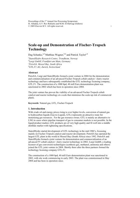
Proceedings <strong>of</strong> the 1 st Annual Gas Processing Symposium<br />
H. Alfadala, G.V. Rex Reklaitis <strong>and</strong> M.M. El-Halwagi (Editors)<br />
© 2009 Elsevier B.V. All rights reserved. 1<br />
<strong>Scale</strong>-<strong>up</strong> <strong>and</strong> <strong>Demonstration</strong> <strong>of</strong> <strong>Fischer</strong>-<strong>Tropsch</strong><br />
<strong>Technology</strong><br />
Dag Schanke, a,d Matthias Wagner, b,d <strong>and</strong> Patrick Taylor c,d<br />
a<br />
StatoilHydro Research Centre, Trondheim, Norway<br />
b<br />
Lurgi GmbH, Frankfurt am Main, Germany<br />
c<br />
PetroSA, Mossel Bay, South Africa<br />
d<br />
GTL.F1 AG, Zurich, Switzerl<strong>and</strong><br />
Abstract<br />
PetroSA, Lurgi <strong>and</strong> StatoilHydro formed a joint venture in 2004 for the demonstration<br />
<strong>and</strong> commercialisation <strong>of</strong> an advanced <strong>Fischer</strong>-<strong>Tropsch</strong> cobalt catalyst / slurry reactor<br />
technology <strong>and</strong> have subsequently established the GTL technology licensing company,<br />
GTL.F1. The construction <strong>of</strong> a 1000 bpd, 40 mill Euro demonstration plant was<br />
sanctioned in 2002 which has been in operation since 2004.<br />
The joint venture has proven the viability <strong>of</strong> an advanced <strong>Fischer</strong>-<strong>Tropsch</strong> cobalt<br />
catalyst <strong>and</strong> reactor technology at a scale that minimises the scale-<strong>up</strong> risk <strong>of</strong> commercial<br />
plants.<br />
Keywords: Natural gas, GTL, <strong>Fischer</strong>-<strong>Tropsch</strong><br />
1. Introduction<br />
With crude oil <strong>and</strong> energy prices rising to ever higher levels, conversion <strong>of</strong> natural gas<br />
to hydrocarbon liquids (Gas-to-Liquids, GTL) represents an attractive route for<br />
monetizing gas resources. For the gas resource owner, GTL is mainly an alternative to<br />
LNG in cases where pipeline transport <strong>of</strong> gas to consumer markets is not possible. In the<br />
liquid product market, GTL products are <strong>of</strong> very high quality <strong>and</strong> fit well into a middle<br />
distillate market with tightening specifications.<br />
StatoilHydro started development <strong>of</strong> GTL technology in the mid 1980’s, focussing<br />
mainly on <strong>Fischer</strong>-<strong>Tropsch</strong> catalyst <strong>and</strong> reactor development. PetroSA has operated the<br />
largest GTL plant in the world in Mossel Bay (South Africa) since 1992. PetroSA <strong>and</strong><br />
StatoilHydro formed a joint venture for demonstration <strong>and</strong> commercialisation <strong>of</strong> an<br />
advanced FT cobalt catalyst / slurry reactor technology in 2002. Lurgi GmbH, a leading<br />
licensor <strong>of</strong> gas conversion technologies (synthesis gas, methanol, ammonia <strong>and</strong> others)<br />
joined the GTL joint venture in 2004. Shortly there after the three partners formed the<br />
technology licensing company GTL.F1.<br />
The construction <strong>of</strong> a 1000 bpd, 40 mill Euro demonstration plant was sanctioned in<br />
2002, with site work commencing in early 2003. The plant was commissioned in May<br />
2004 <strong>and</strong> has been in operation since.
2 D. Schanke et al.<br />
2. FT <strong>Technology</strong> selection <strong>and</strong> scale-<strong>up</strong> issues<br />
2.1. Reactor technology<br />
With cobalt based low temperature FT technology widely recognized as the preferred<br />
technology for maximising middle distillate yields, the choice is between a conventional<br />
tubular fixed-bed reactor configuration <strong>and</strong> the new slurry bubble column type <strong>of</strong><br />
technology (see figure 1). In the fixed-bed reactor, the catalyst pellets (> 1mm size) are<br />
located at the tube side, while the coolant (boiling water) is on the shell side. The slurry<br />
bubble column reactor on the other h<strong>and</strong> has the catalyst (as a finely divided powder) on<br />
the shell side <strong>of</strong> the heat exchanger <strong>and</strong> boiling water inside the tubes. A significant<br />
advantage <strong>of</strong> the latter type <strong>of</strong> reactor is the efficient heat transfer, due to the turbulence<br />
<strong>and</strong> mixing <strong>of</strong> the slurry. This enables the highly exothermic (heat releasing) reaction to<br />
be controlled <strong>and</strong> the reactor can be operated essentially isothermally, which improves<br />
the utilisation <strong>of</strong> catalyst due to the well known fact that the C5+ selectivity <strong>of</strong> a <strong>Fischer</strong>-<br />
<strong>Tropsch</strong> catalyst will decrease with increasing temperature. A further consequence <strong>of</strong><br />
the improved heat transfer is the reduced heat transfer area required, leading to a<br />
maximum capacity <strong>of</strong> a single slurry bubble column reactor currently around 20.000<br />
bpd, compared to approximately 5.000 bpd for a fixed-bed reactor. An additional<br />
benefit <strong>of</strong> the slurry reactor concept is the use <strong>of</strong> small catalyst particles, less than 1/10 th<br />
<strong>of</strong> the size used in a fixed-bed reactor (where the particle size is dictated by the pressure<br />
drop). This avoids intra-particle diffusion limitations which have been shown to give<br />
reduced C5+ selectivity for particles >ca. 0.3 mm.<br />
Steam<br />
Water<br />
TUBULAR FIXED BED REACTOR<br />
SYNGAS<br />
WAX<br />
CATALYST-FILLED TUBES<br />
GAS OUT<br />
SLURRY BUBBLE COLUMN REACTOR<br />
CATALYST-WAX<br />
SLURRY<br />
Steam<br />
Water<br />
SYNGAS<br />
Fig. 1. Simplified sketch <strong>of</strong> tubular fixed-bed reactor <strong>and</strong> slurry bubble column reactor<br />
GAS<br />
OUT<br />
WAX
<strong>Scale</strong>-<strong>up</strong> <strong>and</strong> demonstration <strong>of</strong> <strong>Fischer</strong>-<strong>Tropsch</strong> technology 3<br />
2.2. <strong>Technology</strong> <strong>and</strong> scale-<strong>up</strong> issues<br />
The advantages described in Ch. 2.1. were all identified <strong>and</strong> formed the basis for<br />
StatoilHydro to select the slurry bubble column reactor concept as the preferred FT<br />
technology at an early stage. A small <strong>Fischer</strong>-<strong>Tropsch</strong> (FT) pilot plant was built <strong>and</strong><br />
successfully operated from 1987-1994 to demonstrate the basic viability <strong>of</strong> the slurry<br />
reactor / cobalt catalyst concept.<br />
However, the slurry bubble column concept presents some specific challenges in terms<br />
<strong>of</strong> satisfying key reactor functions as well as scaling <strong>up</strong> to commercial size reactors:<br />
• Separation <strong>of</strong> wax product from the slurry. A significant fraction <strong>of</strong> the product will<br />
not vaporise from the reactor <strong>and</strong> therefore has to be removed from the reactor as<br />
liquid wax from a slurry with relatively high solids concentration. No technology is<br />
available in the open market for such applications.<br />
• Hydrodynamics <strong>and</strong> scale-<strong>up</strong>. A commercial scale slurry reactor will typically have<br />
a diameter <strong>of</strong> 5-10 m. While there is a vast body <strong>of</strong> data available for smaller<br />
columns <strong>and</strong> simple air-water systems, little or no information is available in the<br />
public domain regarding the hydrodynamics <strong>of</strong> very large diameter vessels<br />
operating in the appropriate flow regime <strong>and</strong> at conditions relevant for FT<br />
synthesis.<br />
• Catalyst robustness. The mixing <strong>and</strong> turbulence <strong>of</strong> the 3 phase gas-liquid-solid<br />
makes it necessary to use a catalyst which is resistant to attrition <strong>and</strong> break-<strong>up</strong>.<br />
Formation <strong>of</strong> catalyst fines will not have any negative impact on the catalytic<br />
reaction as such, but will cause problems for wax-slurry separation techniques such<br />
as filtration, sedimentation or hydro-cyclones. Contamination <strong>of</strong> the wax product<br />
with catalyst fines will also lead to increased catalyst consumption as well as<br />
undesired downstream effects in the product <strong>up</strong>grading section <strong>of</strong> a GTL plant.<br />
The concept <strong>of</strong> operating a slurry reactor with cobalt catalyst <strong>and</strong> with continuous wax<br />
separation was proven in small scale pilot plants as well as larger non-reacting mock-<strong>up</strong><br />
units at an early stage. Recognising the potential scale-<strong>up</strong> challenges <strong>of</strong> the technology,<br />
the philosophy <strong>of</strong> the partners has therefore been to go beyond the normal scale-<strong>up</strong><br />
through an intermediate size pilot plant <strong>and</strong> rather build a demonstration plant <strong>of</strong> semicommercial<br />
size in order to minimize further scale-<strong>up</strong> risks for a commercial plant.<br />
3. <strong>Demonstration</strong> plant<br />
Some key data for the semi-commercial demonstration plant are shown in Table 1. <strong>and</strong><br />
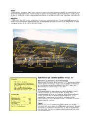
its integration within the main GTL complex in Mossel Bay is shown in Fig. 2.<br />
The demonstration plant is using Syngas from the existing PetroSA GTL plant.<br />
However, the Syngas produced for the high temperature Fe-based FT process in the<br />
PetroSA plant has a higher H2/CO ratio than the optimum ratio employed by the low<br />
temperature cobalt catalyzed process. The composition is therefore adjusted in a
4 D. Schanke et al.<br />
membrane process where some hydrogen is removed <strong>and</strong> returned to the main GTL<br />
plant.<br />
The preheated <strong>and</strong> purified Syngas enters the FT reactor <strong>and</strong> into a slurry <strong>of</strong> finely<br />
divided, s<strong>up</strong>ported cobalt catalyst particles <strong>and</strong> molten wax. Light hydrocarbons,<br />
unconverted Syngas, inert gases <strong>and</strong> water vapor then leave the reactor via an overhead<br />
stream to the product recovery section, where they are separated into oil (C5+<br />
hydrocarbons), aqueous phase <strong>and</strong> tail gas. The wax is separated from the slurry using a<br />
proprietary continuous internal filtration process. The <strong>Fischer</strong>-<strong>Tropsch</strong> reaction also<br />
produces a considerable amount <strong>of</strong> heat that is removed by the generation <strong>of</strong> steam in<br />
heat-exchanger tubes inside the reactor.<br />
The FT catalyst is loaded to the reactor via a separate system <strong>and</strong> catalyst can also be<br />
loaded or removed online during operation.<br />
The demonstration plant is fully integrated with the PetroSA main GTL complex<br />
regarding utilities (nitrogen, plant air, steam, cooling water <strong>and</strong> electricity) <strong>and</strong> product<br />
h<strong>and</strong>ling. The oil products are sent to the PetroSA product <strong>up</strong>grading plant while the<br />
wax product is routed to separate storage. Sharing <strong>of</strong> these functions has significantly<br />
decreased the capital cost <strong>of</strong> the plant compared to a dedicated st<strong>and</strong> alone unit.<br />
Table 1. Key data for semi-commercial plant<br />
Production capacity Up to 1000 bpd<br />
Reactor diameter 2.7 m<br />
Syngas flow Up to 45.000 Nm 3 /h<br />
Total structure height 40 m<br />
Plot area 25 m x 30 m<br />
Total cost Ca. 40 mill Euro<br />
NATURAL<br />
GAS<br />
SYNGAS<br />
PRODUCTION<br />
Gas adjustment<br />
H 2<br />
HIGH TEMP.<br />
F-T<br />
Semi-<br />
Commercial<br />
Demo Plant<br />
Liquids<br />
Wax<br />
PRODUCT<br />
REFINING<br />
Fig. 2. Integration <strong>of</strong> F-T demonstration plant with PetroSA GTL complex at Mossel<br />
Bay, South Africa.
<strong>Scale</strong>-<strong>up</strong> <strong>and</strong> demonstration <strong>of</strong> <strong>Fischer</strong>-<strong>Tropsch</strong> technology 5<br />
Fig. 3. Semi-commercial FT demo plant (Mossel Bay, South Africa)<br />
4. Catalyst production<br />
Scaling <strong>up</strong> production <strong>of</strong> the s<strong>up</strong>ported cobalt FT catalyst, while at the same time<br />
satisfying the strict requirements for use in a slurry reactor, is not a trivial task. Starting<br />
from laboratory recipes for preparation <strong>of</strong> catalyst at typically
6 D. Schanke et al.<br />
To date, more than 100 tonnes <strong>of</strong> catalyst have been produced for use in the semicommercial<br />
demo plant. The scale <strong>of</strong> production (<strong>up</strong> to 1 ton/d) ensures minimal scale<strong>up</strong><br />
risk for the catalyst manufacturing plant for a commercial project.<br />
5. Performance <strong>of</strong> the demonstration plant<br />
5.1. Catalytic performance<br />
During the catalyst manufacturing campaigns, an extensive program <strong>of</strong> quality control<br />
was carried out, using a pilot plant <strong>and</strong> other catalyst test reactors. After developing <strong>and</strong><br />
optimising the catalyst manufacturing procedures, the activity <strong>and</strong> selectivity <strong>of</strong> catalyst<br />
produced at large scale does not differ from catalyst produced in the laboratory.<br />
Furthermore, it was found that the catalyst activity <strong>and</strong> selectivity in the semicommercial<br />
demo plant was similar to what is usually observed in the pilot plant.<br />
Table 2. Example demo plant performance<br />
Feed gas composition<br />
H2<br />
CO<br />
CO2+CH4+N2<br />
58 mol %<br />
27 mol %<br />
Balance<br />
Reactor pressure 1600 kPa<br />
Reactor temperature 232 o C<br />
Gas hourly space velocity 3950 Nm 3 /toncatalyst/h<br />
Conversion per pass<br />
H2<br />
CO<br />
66 %<br />
67 %<br />
5.2. Wax separation<br />
Predictably, the separation <strong>of</strong> wax from the slurry has been the most challenging aspect<br />
<strong>of</strong> the technology development. After very good results in smaller scale pilot reactors,<br />
the first trials in the semi-commercial demo plant gave low wax separation performance<br />
after some time <strong>of</strong> operation <strong>and</strong> higher than expected levels <strong>of</strong> catalyst fines in the wax<br />
product.<br />
After several modifications to the wax separation system as well as the introduction <strong>of</strong> a<br />
2 nd generation FT catalyst, the plant was able to be operated at sustainable, high wax<br />
separation rates with minimal catalyst fines in the wax product (see fig. 4). The<br />
performance <strong>of</strong> the wax separation system is known to be strongly dependent on the<br />
particle size distribution <strong>of</strong> the catalyst in the reactor slurry. It became apparent that the<br />
attrition characteristics <strong>of</strong> the catalyst are a function <strong>of</strong> the scale <strong>of</strong> operation, the<br />
operating conditions as well as the properties <strong>of</strong> the catalyst (Wagner, 2008). This is
<strong>Scale</strong>-<strong>up</strong> <strong>and</strong> demonstration <strong>of</strong> <strong>Fischer</strong>-<strong>Tropsch</strong> technology 7<br />
illustrated in Table 3. Similar observations have been made by Zennaro (2006). Using<br />
the 2 nd generation catalyst gives very low attrition rates in all reactors tested.<br />
Table 3. Attrition rates measured for different catalysts measured in slurry bubble<br />
columns <strong>of</strong> varying scale <strong>and</strong> type.<br />
Relative attrition rate (1 st gen. cat. In pilot plant = 1.0)<br />
Pilot plant Cold-flow column Semi-commercial<br />
plant<br />
1 st gen. catalyst 1.0 0.3 5<br />
2 nd gen. catalyst 0.03 0.01 0.03<br />
SUSTAINABLE WAX SEPARATION RATE (relative)<br />
4,0<br />
3,0<br />
2,0<br />
1,0<br />
0,0<br />
1st gen. cat.<br />
2nd gen. cat.<br />
Pilot plant Cold-flow Semi-commercial<br />
Fig. 4. Relative wax separation rates (wax output/filter surface area, time) for different<br />
catalysts in slurry bubble columns <strong>of</strong> varying scale <strong>and</strong> type.<br />
5.3. Hydrodynamics<br />
The hydrodynamics <strong>of</strong> the semi-commercial reactor was studied using different<br />
methods:<br />
- Overall <strong>and</strong> local gas hold-<strong>up</strong> was estimated using differential pressure<br />
measurements<br />
- Catalyst concentration pr<strong>of</strong>iles were calculated from slurry sampling at several<br />
axial locations<br />
- Temperature pr<strong>of</strong>iles were compared with simulation models
8 D. Schanke et al.<br />
- Injection <strong>of</strong> radioactive tracers (gas, liquid <strong>and</strong> solid) to measure local or global<br />
residence time distributions for the different phases.<br />
The collected data provide unique insight into the hydrodynamics <strong>of</strong> a large scale slurry<br />
bubble column reactor <strong>and</strong> will, together with suitable simulation models (e.g. CFD),<br />
enable a safe scale-<strong>up</strong> to commercial size reactors in terms <strong>of</strong> predicting the<br />
hydrodynamic behaviour. It is also obvious from the measurements that the<br />
extrapolation <strong>of</strong> mixing parameters from models developed in smaller scale columns<br />
would have given incorrect results, thus confirming the need for large scale verification<br />
<strong>of</strong> this type <strong>of</strong> technology.<br />
6. Conclusions<br />
The experience from the technology demonstration project has clearly shown the need<br />
for proving critical technology elements at a sufficient scale. Many <strong>of</strong> the challenges<br />
encountered <strong>and</strong> solved in the project would not have been evident in a smaller scale<br />
test unit. The project has now proven the viability <strong>of</strong> an advanced FT cobalt catalyst <strong>and</strong><br />
reactor technology at a scale that minimises the risk <strong>of</strong> further scale-<strong>up</strong> to commercial<br />
plants.<br />
References<br />
M. Wagner, “Successful large scale <strong>Fischer</strong>-<strong>Tropsch</strong> technology demonstration”, 7 th GTLtec,<br />
Doha 18-19 Feb. 2008<br />
R. Zennaro, “The ENI-IFP/Axens GTL technology for the conversion <strong>of</strong> natural gas”, 6 th World<br />
GTL Summit, London 17-19 May 2006