Scale-up and Demonstration of Fischer-Tropsch Technology
Scale-up and Demonstration of Fischer-Tropsch Technology
Scale-up and Demonstration of Fischer-Tropsch Technology

Create successful ePaper yourself
Turn your PDF publications into a flip-book with our unique Google optimized e-Paper software.
<strong>Scale</strong>-<strong>up</strong> <strong>and</strong> demonstration <strong>of</strong> <strong>Fischer</strong>-<strong>Tropsch</strong> technology 3<br />
2.2. <strong>Technology</strong> <strong>and</strong> scale-<strong>up</strong> issues<br />
The advantages described in Ch. 2.1. were all identified <strong>and</strong> formed the basis for<br />
StatoilHydro to select the slurry bubble column reactor concept as the preferred FT<br />
technology at an early stage. A small <strong>Fischer</strong>-<strong>Tropsch</strong> (FT) pilot plant was built <strong>and</strong><br />
successfully operated from 1987-1994 to demonstrate the basic viability <strong>of</strong> the slurry<br />
reactor / cobalt catalyst concept.<br />
However, the slurry bubble column concept presents some specific challenges in terms<br />
<strong>of</strong> satisfying key reactor functions as well as scaling <strong>up</strong> to commercial size reactors:<br />
• Separation <strong>of</strong> wax product from the slurry. A significant fraction <strong>of</strong> the product will<br />
not vaporise from the reactor <strong>and</strong> therefore has to be removed from the reactor as<br />
liquid wax from a slurry with relatively high solids concentration. No technology is<br />
available in the open market for such applications.<br />
• Hydrodynamics <strong>and</strong> scale-<strong>up</strong>. A commercial scale slurry reactor will typically have<br />
a diameter <strong>of</strong> 5-10 m. While there is a vast body <strong>of</strong> data available for smaller<br />
columns <strong>and</strong> simple air-water systems, little or no information is available in the<br />
public domain regarding the hydrodynamics <strong>of</strong> very large diameter vessels<br />
operating in the appropriate flow regime <strong>and</strong> at conditions relevant for FT<br />
synthesis.<br />
• Catalyst robustness. The mixing <strong>and</strong> turbulence <strong>of</strong> the 3 phase gas-liquid-solid<br />
makes it necessary to use a catalyst which is resistant to attrition <strong>and</strong> break-<strong>up</strong>.<br />
Formation <strong>of</strong> catalyst fines will not have any negative impact on the catalytic<br />
reaction as such, but will cause problems for wax-slurry separation techniques such<br />
as filtration, sedimentation or hydro-cyclones. Contamination <strong>of</strong> the wax product<br />
with catalyst fines will also lead to increased catalyst consumption as well as<br />
undesired downstream effects in the product <strong>up</strong>grading section <strong>of</strong> a GTL plant.<br />
The concept <strong>of</strong> operating a slurry reactor with cobalt catalyst <strong>and</strong> with continuous wax<br />
separation was proven in small scale pilot plants as well as larger non-reacting mock-<strong>up</strong><br />
units at an early stage. Recognising the potential scale-<strong>up</strong> challenges <strong>of</strong> the technology,<br />
the philosophy <strong>of</strong> the partners has therefore been to go beyond the normal scale-<strong>up</strong><br />
through an intermediate size pilot plant <strong>and</strong> rather build a demonstration plant <strong>of</strong> semicommercial<br />
size in order to minimize further scale-<strong>up</strong> risks for a commercial plant.<br />
3. <strong>Demonstration</strong> plant<br />
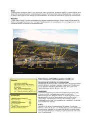
Some key data for the semi-commercial demonstration plant are shown in Table 1. <strong>and</strong><br />
its integration within the main GTL complex in Mossel Bay is shown in Fig. 2.<br />
The demonstration plant is using Syngas from the existing PetroSA GTL plant.<br />
However, the Syngas produced for the high temperature Fe-based FT process in the<br />
PetroSA plant has a higher H2/CO ratio than the optimum ratio employed by the low<br />
temperature cobalt catalyzed process. The composition is therefore adjusted in a