BP 4 CT (Turbo) Stage Projector - Pani Projection and Lighting
BP 4 CT (Turbo) Stage Projector - Pani Projection and Lighting
BP 4 CT (Turbo) Stage Projector - Pani Projection and Lighting

You also want an ePaper? Increase the reach of your titles
YUMPU automatically turns print PDFs into web optimized ePapers that Google loves.
<strong>Stage</strong> <strong>Projector</strong> <strong>BP</strong> 4 <strong>CT</strong> <strong>Pani</strong> <strong>Projection</strong> <strong>and</strong> <strong>Lighting</strong> Vertriebs GmbH<br />
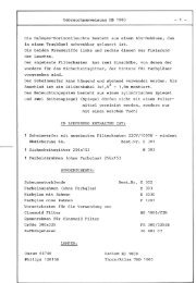
7) Electrical Connection<br />
(See Electrical Schematic 230- 02- 01/a)<br />
The HMI <strong>Stage</strong> <strong>Projector</strong> <strong>BP</strong> 4 <strong>CT</strong> is used in conjunction with the ballast 4000 W,<br />
220/240V- 50 Hz, 208/220V- 60 Hz (Order Code: 19203).<br />
The ballast incorporates a choke which limits lamp power to 24 A.<br />
Main power is interrupted when the projector housing is opened.<br />
7.1) Main Power Connection<br />
Universal - ballast 4000 W, 220/240 V- 50 Hz, 208/ 220 V- 60 Hz<br />
Main Power Cable 3x 4 square millimeters, two meters long with open leads<br />
Phase R: brown, Neutral N: blue, Ground PE: yellow/green<br />
Connected to power source 230 V/ 50 Hz, 25 A<br />
7.2) Connecting Cable Ballast - <strong>Projector</strong><br />
On the Universal - ballast there is one lamp current cable mounted with a CEE -<br />
clutch 4x 32 A <strong>and</strong> one remote cable with a 10-pin clutch. St<strong>and</strong>ardlength is 3 m<br />
(may be extended – for extremely long runs wire gauge may need to be larger). Both<br />
cables are connected to the projector by using the mounted plugs.<br />
The "ON" <strong>and</strong> the "OFF“ function can be performed at either the ballast or the<br />
projector. Thus, it is possible to locate the ballast away from the projector.<br />
7.3) Remote Ignition - DMX 512<br />
For ignition <strong>and</strong> shut down of the projector by a DMX 512 signal, a relay card <strong>and</strong><br />
associated DMX In connector are located on the projector (Ignition Pos. 8). In<br />
addition the optional Universal DMX 512 interface <strong>and</strong> the corresponding ignition<br />
cable are necessary (for further information see the instruction manual of the<br />
Universal DMX 512 Interface).<br />
POSITION NUMBERS SEE PAGE 6<br />
15