1 HQI 2000 W/ D/ S bulb 37601 - Pani Projection and Lighting
1 HQI 2000 W/ D/ S bulb 37601 - Pani Projection and Lighting
1 HQI 2000 W/ D/ S bulb 37601 - Pani Projection and Lighting

You also want an ePaper? Increase the reach of your titles
YUMPU automatically turns print PDFs into web optimized ePapers that Google loves.
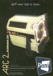
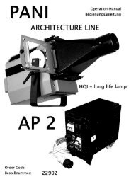
Architecture Projector ARC 2/ <strong>HQI</strong> PANI <strong>Projection</strong> <strong>and</strong> <strong>Lighting</strong> Vertriebs GmbH.<br />
7) Fitting accessories into front panel<br />
There are three groups of four recesses arranged in a square (fig.2/ 11.1, 11.2, 11.3) in<br />
the front panel (fig.2/ 10) to receive accessories. After unscrewing the two corresponding<br />
knurled screws (fig.1/ 12), the accessory fitting adapters (e.g. (fig.6/ 29)) are slid into the<br />
recesses (fig.2/ 11.1, 11.2, 11.3), pushed downwards so that the accessory “engages”,<br />
then fix into place with the knurled screws (fig.1/ 12).<br />
Important:<br />
Always fully unscrew knurled screws (fig.1/ 12) when removing accessories to simplify any<br />
future fitting operations.<br />
7.1) Fitting slide carrier <strong>and</strong> adjusting slide<br />
The slide carrier (fig. 6) must be located in the recesses (fig.2/ 11.3). For adjusting the<br />
slide to given edges in case of oblique projections, open the knurled screws (fig. 6 / 32),<br />
turn the twisting plate <strong>and</strong> fix it in the desired angle position.<br />
In the case of oblique projections it may be a problem to get an allover sharp projection.<br />
Following old optical rules you are able to adjust the projection by canting the slide out of<br />
the right angle. Therefore use the provided 4 knurled screws (fig.6 / 33). Try the effect until<br />
it fits. Depending on the focal length, the projection distance <strong>and</strong> the setting, it is possible<br />
to adjust angles up to more than 45° from the parallel st<strong>and</strong>ard projection.<br />
Only the optical distorsion <strong>and</strong> the shifting of light intensity from the shortest to the highest<br />
distance of the projection have to be corrected in an other way.<br />
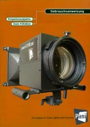
7.2) Installing an objective in objective adapter (fig.7)<br />
The objective is fitted into the objective adapter (fig.7) <strong>and</strong> fixed in place with four screws<br />
(fig.7/ 30).<br />
7.2.1) Setting up objective in projector<br />
Locate the objective adapter (fig.8) in the recesses (fig.2/ 11.2).<br />
8) Control panel on the projector<br />
The service time counter (fig.3/ 17) is located on the back of the projector along with four<br />
230 VAC sockets for accessories (fig.3/ 18)<br />
4