Lock Gates and Operating Equipment - Publications, US Army Corps ...
Lock Gates and Operating Equipment - Publications, US Army Corps ...
Lock Gates and Operating Equipment - Publications, US Army Corps ...

You also want an ePaper? Increase the reach of your titles
YUMPU automatically turns print PDFs into web optimized ePapers that Google loves.
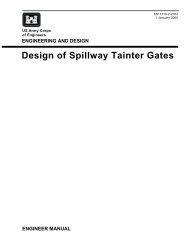
<strong>US</strong> <strong>Army</strong> <strong>Corps</strong><br />
of Engineers<br />
ENGINEERING AND DESIGN<br />
<strong>Lock</strong> <strong>Gates</strong> <strong>and</strong><br />
<strong>Operating</strong> <strong>Equipment</strong><br />
ENGINEER MANUAL<br />
EM 1110-2-2703<br />
30 June 1994
DEPARTMENT OF THE ARMY EM 1110-2-2703<br />
U.S. <strong>Army</strong> <strong>Corps</strong> of Engineers<br />
CECW-EE Washington, DC 20314-1000<br />
Manual<br />
No. 1110-2-2703 30 June 1994<br />
Engineering <strong>and</strong> Design<br />
LOCK GATES AND OPERATING EQUIPMENT<br />
1. Purpose. This manual provides guidance in the structural, mechanical, <strong>and</strong> electrical design of<br />
lock gates <strong>and</strong> operating equipment at navigation projects.<br />
2. Applicability. This manual applies to all HQ<strong>US</strong>ACE elements, major subordinate comm<strong>and</strong>s,<br />
districts, laboratories, <strong>and</strong> field operating activities having responsibilities for the design <strong>and</strong> construction<br />
of civil works projects.<br />
FOR THE COMMANDER:<br />
WILLIAM D. BROWN<br />
Colonel, <strong>Corps</strong> of Engineers<br />
Chief of Staff<br />
____________________________________________________________________________________<br />
This manual supersedes EM 1110-2-2703, dated 29 February 1984.
DEPARTMENT OF THE ARMY EM 1110-2-2703<br />
U.S. <strong>Army</strong> <strong>Corps</strong> of Engineers<br />
CECW-EE Washington, D.C. 20314<br />
Manual<br />
No. 1110-2-2703 30 June 1994<br />
Subject Paragraph Page<br />
Chapter 1<br />
Introduction<br />
Purpose ....................... 1-1 1-1<br />
Applicability .................... 1-2 1-1<br />
References ..................... 1-3 1-1<br />
Applicable Computer Programs ....... 1-4 1-1<br />
Plates ......................... 1-5 1-1<br />
General ........................ 1-6 1-1<br />
Materials <strong>and</strong> Working Stresses ....... 1-7 1-3<br />
Basic Dimensions ................ 1-8 1-4<br />
Loads ......................... 1-9 1-4<br />
Fatigue <strong>and</strong> Fracture Control ......... 1-10 1-5<br />
<strong>Operating</strong> Machinery General Design<br />
Criteria ....................... 1-11 1-5<br />
Chapter 2<br />
Miter <strong>Gates</strong><br />
Miter <strong>Gates</strong>, Horizontally Framed ..... 2-1 2-1<br />
Miter <strong>Gates</strong>, Horizontally Framed-<br />
Arch Type .................... 2-2 2-19<br />
Miter <strong>Gates</strong>, Vertically Framed ....... 2-3 2-19<br />
Erection <strong>and</strong> Testing, Miter <strong>Gates</strong> ..... 2-4 2-22<br />
<strong>Operating</strong> Machinery .............. 2-5 2-23<br />
Chapter 3<br />
Diagonal Design, Miter <strong>Gates</strong><br />
Diagonal Design ................. 3-1 3-1<br />
Definitions of Terms <strong>and</strong> Symbols ..... 3-2 3-1<br />
Introduction .................... 3-3 3-2<br />
Geometry ...................... 3-4 3-2<br />
Example 1, Horizontally Framed Gate . . 3-5 3-15<br />
Example 2, Vertically Framed Gate .... 3-6 3-21<br />
Vertical Paneling of Leaf ........... 3-7 3-27<br />
Derivation of Equation 3-11’ ......... 3-8 3-30<br />
Temporal Hydraulic Loads .......... 3-9 3-30<br />
Procedure for Prestressing<br />
Diagonals ..................... 3-10 3-32<br />
Engineering <strong>and</strong> Design<br />
LOCK GATES AND OPERATING EQUIPMENT<br />
Table of Contents<br />
Subject Paragraph Page<br />
New Information on<br />
Diagonal Design ................ 3-11 3-32<br />
Chapter 4<br />
Sector <strong>Gates</strong><br />
Sector <strong>Gates</strong> .................... 4-1 4-1<br />
<strong>Operating</strong> Machinery .............. 4-2 4-4<br />
Chapter 5<br />
Vertical-Lift <strong>Gates</strong><br />
Vertical-Lift <strong>Gates</strong> ................ 5-1 5-1<br />
<strong>Operating</strong> Machinery .............. 5-2 5-7<br />
Chapter 6<br />
Submergible Tainter <strong>Gates</strong><br />
Design Analysis .................. 6-1 6-1<br />
Seal <strong>and</strong> Gate Deicing ............. 6-2 6-1<br />
<strong>Operating</strong> Machinery .............. 6-3 6-1<br />
Chapter 7<br />
Corrosion Control<br />
Corrosive Environment of <strong>Lock</strong> <strong>Gates</strong> . . 7-1 7-1<br />
Corrosion <strong>and</strong> Corrosion Control ...... 7-2 7-1<br />
Painting Structures ................ 7-3 7-1<br />
Type of Cathodic Protection ......... 7-4 7-2<br />
Cathodic-Protection Operation ........ 7-5 7-2<br />
Anode Concepts ................. 7-6 7-2<br />
Flooding <strong>and</strong> Emergency<br />
Maintenance ................... 7-7 7-2<br />
Cathodic-Protection Tests, Adjustments,<br />
<strong>and</strong> Reports ................... 7-8 7-3<br />
Measurement of Existing Cathodic-<br />
Protection Systems ............... 7-9 7-3<br />
Cathodic Protection for Miter <strong>and</strong><br />
Quoin Blocks .................. 7-10 7-3<br />
i
EM 1110-2-2703<br />
30 Jun 94<br />
Subject Paragraph Page<br />
Appendix A<br />
References .................... A-1<br />
Appendix B<br />
Illustrative Plates ............... B-1<br />
Appendix C<br />
Sample Computations ........... C-1<br />
Appendix D<br />
Air Bubbler Gate<br />
Recess Flusher ................ D-1<br />
ii
Chapter 1<br />
Introduction<br />
1-1. Purpose<br />
This manual provides guidance in the structural, mechanical,<br />
<strong>and</strong> electrical design of lock gates <strong>and</strong> operating<br />
equipment at navigation projects.<br />
1-2. Applicability<br />
This manual applies to all HQ<strong>US</strong>ACE elements, major<br />
subordinate comm<strong>and</strong>s, districts, laboratories, <strong>and</strong> field<br />
operating activities having responsibilities for the design<br />
<strong>and</strong> construction of civil works projects.<br />
1-3. References<br />
References are listed in Appendix A.<br />
1-4. Applicable Computer Programs<br />
CMITER, Computer Aided Structural Engineering,<br />
U.S. <strong>Army</strong> Engineer Waterways Experiment Station,<br />
3909 Halls Ferry Road, Vicksburg, MS 39180-6199.<br />
1-5. Plates<br />
Illustrative plates containing general information, typical<br />
details, mechanical design data, <strong>and</strong> sample computations<br />
are included in Appendix B, <strong>and</strong> are referred to herein as<br />
Plate B-1, B-2, etc.<br />
1-6. General<br />
a. Function of gates. <strong>Lock</strong> gates serve a number of<br />
different functions, depending on location <strong>and</strong> conditions.<br />
While the major use of lock gates is to form the<br />
damming surface across the lock chamber, they may also<br />
serve as guard gates, for filling <strong>and</strong> emptying the lock<br />
chamber, for passing ice <strong>and</strong> debris, to unwater the lock<br />
chamber, <strong>and</strong> to provide access from one lock wall to the<br />
other by means of walkways or bridgeways installed on<br />
top of the gates. A navigation lock requires closure gates<br />
at both ends of the lock so that the water level in the<br />
lock chamber can be varied to coincide with the upper<br />
<strong>and</strong> lower approach channels. The sequence of “locking”<br />
a vessel upstream is: first, lower the water level in the<br />
lock to the downstream water level; second, open the<br />
lower gate <strong>and</strong> move the vessel into the lock chamber;<br />
third, close the lower gate <strong>and</strong> fill the lock chamber to<br />
the level of the upper pool; <strong>and</strong> finally, open the<br />
EM 1110-2-2703<br />
30 Jun 94<br />
upstream gate <strong>and</strong> move the vessel out of the lock.<br />
<strong>Lock</strong>age of a vessel downstream involves a similar<br />
sequence in reverse order.<br />
b. Types of gates covered.<br />
(1) Miter gates. A very large percentage of the<br />
locks in the United States are equipped with double-leaf<br />
miter gates which are used for moderate- <strong>and</strong> high-lift<br />
locks. These gates are fairly simple in construction <strong>and</strong><br />
operation <strong>and</strong> can be opened or closed more rapidly than<br />
any other type of gate. Maintenance costs generally are<br />
low. A disadvantage of this gate is that it cannot be used<br />
to close off flow in an emergency situation with an<br />
appreciable unbalanced head.<br />
(a) Miter gates fit into recesses in the wall in the<br />
open position. The bottom of the recess should extend<br />
below the gate bottom to preclude operating difficulties<br />
from silt <strong>and</strong> debris collection. Enlarged recesses are<br />
sometimes used to facilitate the removal of accumulated<br />
ice. An air bubbler system is recommended to help clear<br />
ice <strong>and</strong> debris from gate recesses. (See Appendix D for<br />
typical air bubbler recess flusher.)<br />
(b) Miter gates are framed either horizontally or<br />
vertically. The skin plate of a horizontally framed gate is<br />
supported by horizontal members which may be either<br />
straight girders acting as beams, or circular arches. Each<br />
such horizontal member is supported by the vertical<br />
quoin post at one end <strong>and</strong> the miter post at the other.<br />
All water load is transmitted through the girders <strong>and</strong><br />
quoin blocking into the gate monoliths. A vertically<br />
framed gate resists the water pressure by a series of<br />
vertical girders more or less uniformly spaced throughout<br />
the length of the gate, <strong>and</strong> supported at top <strong>and</strong> bottom<br />
by horizontal girders transmitting the loads to miter <strong>and</strong><br />
quoin at the top of the leaf, <strong>and</strong> directly to the sill at the<br />
bottom.<br />
(c) The relative costs of the two types of gates (horizontally<br />
<strong>and</strong> vertically framed) depend largely upon three<br />
main factors:<br />
- Overall weight of the gate;<br />
- Simplicity of design <strong>and</strong> ease of fabrication <strong>and</strong><br />
erection;<br />
- Cost of that part of the lock walls <strong>and</strong> sills influenced<br />
by the design of the gates.<br />
1-1
EM 1110-2-2703<br />
30 Jun 94<br />
(d) When the ratio of the height of a leaf to its width<br />
is greater than about 0.7, the horizontally framed gate<br />
will weigh less. For long, shallow gates, vertical framing<br />
requires less material.<br />
(e) The overturning moment carried to the lock wall<br />
by a horizontally framed gate is greater about all points<br />
below the sill than that caused by a vertically framed<br />
gate, unless the entire sill load is transmitted to the wall.<br />
Hence, the latter type requires less masonry in a thrust<br />
wall of gravity section, but the heavier sill necessary to<br />
support the bottom girder into which the verticals are<br />
framed may counterbalance this saving.<br />
(f) Due to the greater rigidity <strong>and</strong> resistance to boat<br />
impact of the horizontally framed gate <strong>and</strong> the insignificant<br />
difference in cost, the vertically framed gate will no<br />
longer be used except for unusual applications <strong>and</strong> upon<br />
special approval.<br />
(2) Sector gates. A sector gate is similar in shape to<br />
a tainter gate except it is oriented to rotate about a vertical<br />
axis <strong>and</strong> is supported at the top <strong>and</strong> bottom in a manner<br />
similar to a miter gate. Like miter gates, sector gates<br />
are used in pairs, meeting at the center of the lock when<br />
in the closed position <strong>and</strong> swinging into recesses in the<br />
lock walls for the open position. The trunnions are<br />
located in the lock walls, <strong>and</strong> the skin plates face in the<br />
direction of the normally higher pool level.<br />
(a) Sector gates are used at both ends of locks that<br />
are located in tidal reaches of rivers or canals where the<br />
lifts are low <strong>and</strong> where the gates may be subjected to<br />
reversal of heads. Since these gates can be opened <strong>and</strong><br />
closed under head, they can be used to close off flow in<br />
an emergency. The gates swing apart <strong>and</strong> water flows<br />
into or out of the lock through the center opening<br />
between the gates. In some cases, flow is admitted<br />
through culverts to improve filling characteristics or<br />
where ice or drift may not permit adequate flow between<br />
the gates.<br />
(b) Because the turbulence area at the upper end of a<br />
lock filled by a sector gate is not effective for lockage of<br />
vessels, the length of the lock chambers must be<br />
increased proportionately. Model tests indicate that about<br />
100 feet (ft) of additional length is required. Like other<br />
end-filling systems, sector gates cannot be used for filling<br />
<strong>and</strong> emptying high-lift locks unless the filling <strong>and</strong> emptying<br />
rates are greatly reduced. The practical lift limitation<br />
is usually about 10 ft, although gates with higher lifts<br />
have been built.<br />
1-2<br />
(c) The disadvantages of the sector gates are high<br />
construction cost, long opening <strong>and</strong> closing times, <strong>and</strong><br />
larger wall recesses.<br />
(3) Vertical-lift gates. Vertical-lift gates may be<br />
used at both ends of a lock, or at only one end in combination<br />
with a miter gate at the other end. They can be<br />
raised or lowered under low to moderate heads but are<br />
not used when there is reversed head. Their operation<br />
time is much slower for older gates <strong>and</strong> maintenance<br />
costs are higher than those of miter gates, but they can<br />
be used in emergency closure. The newer gates, however,<br />
are capable of achieving operating speeds equal to,<br />
or even faster than, miter gates.<br />
(a) A vertical-lift gate installation at the upstream<br />
end of a lock normally consists of a single-leaf submergible<br />
gate, which rises vertically to close off the lock<br />
chamber from the upper pool. When the lock is filled,<br />
the gate is opened by sliding the leaf vertically downward<br />
until the top of the leaf is at or below the top of the<br />
upper sill.<br />
(b) In some cases, a double-leaf vertical-lift gate<br />
may be used. The upper leaf can be provided with a<br />
curved crest which permits overflow to supplement flow<br />
from the primary filling system when the lock chamber is<br />
nearly full. This type of gate can also be used for skimming<br />
ice <strong>and</strong> debris.<br />
(c) When a vertical-lift gate is used at the downstream<br />
end of a lock, it is raised vertically to a height<br />
above the lower pool level so that vessels can pass<br />
underneath. The gate leaf is suspended from towers on<br />
the lock walls <strong>and</strong> may be equipped with counterweights<br />
to reduce the power hoist size. <strong>Lock</strong> gates of this type<br />
are practical only for very high locks <strong>and</strong> where required<br />
vertical clearance can be provided under the gate in its<br />
raised position.<br />
(4) Submergible tainter gates. The locks of the<br />
Dalles Dam, some Lower Snake River projects, <strong>and</strong> the<br />
Upper <strong>and</strong> Lower St. Anthony Falls <strong>Lock</strong>s have submergible<br />
tainter gates. This type of gate is raised to<br />
close the lock chamber <strong>and</strong> lowered into the lock chamber<br />
to open it. The end frames are recessed into the lock<br />
wall so no part of the end frame projects into the passageway.<br />
This type of gate was chosen because it is<br />
structurally efficient <strong>and</strong> was estimated to be lighter in<br />
weight <strong>and</strong> less costly than a double-leaf miter gate for<br />
these applications. Also, the tainter gate permitted the<br />
length of the approach channel to be reduced by the leaf
width of the miter gate. There are two potential problem<br />
areas in the operation of this type of gate: skewing of<br />
gate during opening <strong>and</strong> closing, <strong>and</strong> vulnerability to<br />
damage if hit by lock traffic. However, with good<br />
design practices <strong>and</strong> lock management, these problems<br />
will be minimal.<br />
1-7. Materials <strong>and</strong> Working Stresses<br />
a. Materials. This manual serves only as a guide<br />
<strong>and</strong> the following list should not be considered as a<br />
complete listing of materials that may be used.<br />
(1) Structural steel. <strong>Lock</strong> gates are usually constructed<br />
of structural grade carbon steel having a yield<br />
point of 36,000 pounds per square inch (psi). Low-alloy<br />
steel, with a yield point up to 50,000 psi, is quite frequently<br />
used as skin plate in conjunction with structural<br />
grade girders. In some cases for the larger gates, other<br />
than miter gates, low-alloy steel may be economical for<br />
the complete gate. The deflection of members fabricated<br />
of high-strength low-alloy steel should always be investigated<br />
as it will always be more severe than if the members<br />
were of structural grade carbon steel. For miter<br />
gates, structural grade carbon steel should be used<br />
regardless of the gate height in the interest of providing a<br />
more rigid gate, except for the skin plate <strong>and</strong> diagonals<br />
which may be of high-strength, low-alloy steel whenever<br />
warranted.<br />
(2) Corrosion-resistant steel. Corrosion-resistant<br />
steel normally should only be used in locations where<br />
corrosion is expected to be severe or where corrosion<br />
will impair the normal efficiency of gate operation.<br />
Under most conditions, seal contact surfaces of lock<br />
gates are not required to be corrosion resistant but under<br />
adverse conditions corrosion-resistant clad or solid stainless<br />
steel plates may be desirable. For some lock locations<br />
<strong>and</strong> conditions it may also be desirable to clad the<br />
contact surfaces of miter <strong>and</strong> quoin blocks with corrosion-resistant<br />
steel or to use solid stainless or corrosionresistant<br />
steel miter <strong>and</strong> quoin contact blocks. Flame<br />
spraying of corrosion-resisting steel particles to surfaces<br />
subject to severe corrosion may be advantageous where<br />
using solid or clad corrosion-resisting steel is not practical<br />
or not economical. The new guide specification<br />
CW-05036 covers the requirements for surface preparation<br />
<strong>and</strong> applications of metalizing/flame spraying<br />
coatings.<br />
(3) Cast steel. The operating strut pin bearing<br />
collars, pintle sockets, <strong>and</strong> pintle shoes are normally<br />
fabricated of cast steel, utilizing mild-strength to<br />
EM 1110-2-2703<br />
30 Jun 94<br />
medium-strength carbon steel castings. For items that are<br />
subjected to higher stresses than medium-strength castings<br />
are capable of carrying, such as the miter guide<br />
roller <strong>and</strong> pintle balls, high-strength, low-alloy steel<br />
castings should be used.<br />
(4) Forged steels. Gudgeon pins, operating strut<br />
connecting pins, anchor link pins, parts of the anchorage<br />
links, <strong>and</strong> guide roller pins should be made of carbon<br />
steel forgings rated for general industrial use. Forgings<br />
may be untreated or heat-treated depending on intended<br />
use <strong>and</strong> requirements. The pintle ball of most gates is<br />
made of an alloy steel forging containing nickel, giving<br />
the forging a good allowable bearing value as well as a<br />
fair degree of corrosion resistance. Corrosion-resistant<br />
weld overlays may also be used on pintle balls in highly<br />
corrosive environments.<br />
(5) Bronze. Bushings for all lock gate components<br />
are normally made of bronze. Usually bearings are made<br />
of a bronze designated for general purpose applications.<br />
Where stresses are encountered that are higher than desirable<br />
for the general purpose bronze, aluminum bronze<br />
may be used.<br />
(6) Bolts. Where bolted connections are used for<br />
parts of the gate that may have to be removed for maintenance<br />
or repair, a copper-nickel alloy, usually referred<br />
to as monel, or an equally corrosion-resistant steel should<br />
be considered, especially if corrosive elements are present.<br />
The 300 series stainless steel <strong>and</strong> bronze bolts, nuts,<br />
washers, <strong>and</strong> setscrews have been used with good results<br />
in highly corrosive environments. Ordinarily, bolts, nuts,<br />
<strong>and</strong> washers should all be made from the same type of<br />
material; however, if salvage <strong>and</strong> reuse is intended different<br />
alloy combinations for bolts <strong>and</strong> nuts should be used<br />
to minimize seizing. Normal applications of this type of<br />
connection are pintle socket to gate connection, quoin<br />
<strong>and</strong> miter water seal bolts, <strong>and</strong> bolts for the bottom seal.<br />
Where bolts are used <strong>and</strong> corrosion is not a factor,<br />
ASTM A307 or A325 bolts should be used, with bolt<br />
strength dictated by load <strong>and</strong> conditions.<br />
(7) Fabrication. Fabrication of all lock gates should<br />
be by welding, with bolts being used only for those parts<br />
that may have to be removed for maintenance or repair.<br />
The application of welding generally results in lighter<br />
<strong>and</strong> stronger gates. All welding should be done in accordance<br />
with the current Structural Welding Code of the<br />
American Welding Society, Section 9, Design of New<br />
Bridges.<br />
1-3
EM 1110-2-2703<br />
30 Jun 94<br />
b. Design strength. Structural steel gate members<br />
shall be designed in accordance with the requirements of<br />
EM 1110-2-2105. For general purpose bronze bushings,<br />
the allowable bearing should be below 1,500 psi with a<br />
maximum concentrated bearing of not more than<br />
5,000 psi (this refers to a bushing with an eccentric<br />
load). Where a higher allowable bearing is desirable,<br />
aluminum bronze may be used with working stresses up<br />
to 5,000 psi <strong>and</strong> a concentrated bearing of not more than<br />
10,000 psi as described above. Working stresses for both<br />
forgings <strong>and</strong> castings should be based on yield strength<br />
<strong>and</strong> for normal applications should be no more than<br />
0.50F y.<br />
1-8. Basic Dimensions<br />
a. Miter gates. A miter gate is a three-hinged arch<br />
when the leaves are mitered. Gate geometry is a function<br />
of the angle the work line of the leaf makes with a<br />
line normal to the lock walls, with the gate in a mitered<br />
position. Past study <strong>and</strong> design have determined that for<br />
miter gates a slope of 1L on 3T gives the best results<br />
(L = longitudinal, T = transverse). In general, vertically<br />
framed gates have been used where the height-to-length<br />
ratio of the leaf was less than 0.5. The approximate ratio<br />
of height to length, where the weight of a vertically<br />
framed leaf is essentially the same as a horizontally<br />
framed leaf, is somewhere between 0.70 <strong>and</strong> 1.0 (see<br />
paragraph 1-6b(1)). However, vertically framed gates are<br />
not recommended for new construction. Even with a<br />
slight increase in cost, the greater rigidity of the horizontally<br />
framed gates makes them more desirable.<br />
(1) The pintle is located so that the leaf, when<br />
recessed, is completely within the lock wall <strong>and</strong> so that<br />
the pintle is eccentric (upstream) with respect to the<br />
center of curvature of the bearing face of the quoin contact<br />
block. The center of curvature of the bearing face is<br />
always located on the line tangent to the thrust line at the<br />
quoin contact point. The pintle eccentricity, which<br />
makes the quoin block approach the contact point tangentially,<br />
should be approximately 7 in., thereby reducing<br />
the possibility of metal interference (see paragraph 2-1h).<br />
(2) The arch-type miter gate is a horizontally framed<br />
structural system of curved members with a composite<br />
acting skin plate. Except for the curvature, the gate size<br />
<strong>and</strong> other components are similar to or the same as horizontally<br />
framed straight gates.<br />
b. Sector gates. Sector gates are generally laid out<br />
with the frames forming an equilateral triangle. The<br />
normal layout is for 60 degrees (deg) or greater interior<br />
1-4<br />
angles, formed by the frames <strong>and</strong> a chord line behind the<br />
skin plates. One strut is parallel to the lock wall in the<br />
closed position, thereby causing the other strut to form an<br />
angle equal to the interior angle, with the lock wall.<br />
The pintle is located so that the gate is completely in the<br />
recess in the open position.<br />
c. Vertical-lift gates. Dimensions for vertical-lift<br />
gates are based solely on lock width <strong>and</strong> girder depths<br />
required by the head. Recesses in lock walls for upper<br />
gates are determined by load, girder depth, <strong>and</strong> detail<br />
requirements. Towers for downstream gates are also<br />
determined by load, counterweights, <strong>and</strong> related details.<br />
d. Submergible tainter gates. As with spillway<br />
tainter gates, the controlling dimensions are the lock<br />
width, gate radius, <strong>and</strong> end frame <strong>and</strong> trunnion hub<br />
location. Plates B-45 <strong>and</strong> B-46 show typical end frame<br />
<strong>and</strong> cross section of the gate.<br />
1-9. Loads<br />
The loads applicable to lock gate design are dead, hydrostatic,<br />
hydraulic, temporal, <strong>and</strong> boat impact. Miter gates<br />
are also subject to torsion. Dead load is the weight of<br />
the structure plus mud <strong>and</strong> ice; hydrostatic load is the<br />
water load on the gate produced by the pool differential;<br />
boat impact is the dynamic force applied to the gate by<br />
the barge impact; temporal load is the water surge forces<br />
from wave loads or overfilling of the lock; <strong>and</strong> torsion<br />
on miter gates is the result of a twisting action from the<br />
operating strut force <strong>and</strong> the water resistance caused by<br />
the leaf moving. For more specific lock gate loads, see<br />
the gate type’s respective section herein.<br />
a. The controlled upper <strong>and</strong> lower pools cause the<br />
normal loading, <strong>and</strong> greater water forces, such as<br />
unwatering the lock, are considered emergency conditions,<br />
with an increase in allowable stress of 33 percent.<br />
b. The force of impact usually is limited by local<br />
failure in the region of impact. For design purposes, this<br />
force, supported by past designs, is converted into an<br />
equivalent water load of 10- to 15-ft head below the top<br />
girder <strong>and</strong> of 6- to 10-ft head above the top girder for<br />
vertical-lift gates if horizontally framed. An impact load<br />
of 250,000 or 400,000 pounds (lb), according to location<br />
of load, is applied above the pool to horizontally framed<br />
miter gates. (See paragraph 2-1b(1)(d).) Barge or<br />
impact force is generally not applied to vertical framing<br />
members. Greater impact forces or the use of barriers<br />
may be justified based on the importance of the waterway<br />
or type of traffic.
c. On sector gates a design withst<strong>and</strong>ing a concentrated<br />
impact force of 125,000 lb applied to the top horizontal<br />
girder is recommended, with vertical framing<br />
members designed for no impact loading.<br />
d. The quoin end of a miter gate leaf is held vertical<br />
by the pintle <strong>and</strong> gudgeon pin, leaving the miter end free<br />
to twist out of vertical alignment. The deadweight of the<br />
leaf, along with ice or mud, also causes the leaf to twist.<br />
To keep the leaf in vertical alignment while stationary,<br />
<strong>and</strong> to eliminate excessive deflection during operation,<br />
diagonals are provided on the downstream faces of horizontally<br />
framed miter gates <strong>and</strong> on both upstream <strong>and</strong><br />
downstream faces of vertically framed miter gates.<br />
These diagonals act as tension members for all normal<br />
gate operations. (See <strong>US</strong>AED, Chicago 1960.)<br />
1-10. Fatigue <strong>and</strong> Fracture Control<br />
All possible modes of failure should be considered when<br />
designing lock gates. Possible failure modes are:<br />
1) general yielding or excessive plastic deformation,<br />
2) buckling or general instability, 3) subcritical crack<br />
growth leading to loss of cross section or unstable crack<br />
growth, <strong>and</strong> 4) unstable crack extension leading to failure<br />
of a member. Failure modes 1 <strong>and</strong> 2 are addressed by<br />
Load <strong>and</strong> Resistance Factor Design (LRFD) <strong>and</strong> Allowable<br />
Stress Design (ASD) principles whereas failure<br />
modes 3 (fatigue) <strong>and</strong> 4 (brittle fracture) can be<br />
addressed using fatigue <strong>and</strong> fracture mechanics principles.<br />
Welded construction with its emphasis on monolithic<br />
structural members has led to the increased<br />
desirability of including fracture criterion in addition to<br />
strength <strong>and</strong> buckling criteria when designing a structure.<br />
Stress range, detailing, <strong>and</strong> the number <strong>and</strong> frequency of<br />
load cycles control fatigue while geometry, toughness,<br />
<strong>and</strong> stress levels control fracture. For further guidance,<br />
see EM 1110-2-2105.<br />
a. Fatigue requirements. Fatigue can be controlled<br />
by stress range, detailing, <strong>and</strong> the number <strong>and</strong> frequency<br />
of load cycles. While the number <strong>and</strong> frequency of load<br />
cycles are usually controlled by the structure’s purpose,<br />
the designer can control the stress range <strong>and</strong> the choice<br />
of detail. Refer to AISC (Current Edition), Appendix K,<br />
for guidance in design <strong>and</strong> detailing.<br />
b. Fracture control requirements. The designer<br />
should set limits on tensile stress levels, enforce controls<br />
on quality fabrication <strong>and</strong> inspection procedures to minimize<br />
initial defects <strong>and</strong> residual stresses, designate the<br />
appropriate temperature zone, <strong>and</strong> specify the related<br />
minimum fracture toughness for critical members <strong>and</strong>/or<br />
EM 1110-2-2703<br />
30 Jun 94<br />
components. For lock gates, fracture critical members<br />
shall be defined as “members <strong>and</strong> their associated connections<br />
subjected to tensile stresses <strong>and</strong> whose failure<br />
would cause the structure to be inoperable.” For<br />
minimum Charpy V-notch impact test values see<br />
EM 1110-2-2105.<br />
1-11. <strong>Operating</strong> Machinery General Design<br />
Criteria<br />
a. Machinery components. All components of the<br />
gate operating or hoisting machinery except compression<br />
members which may fail by buckling should be designed<br />
for loads or forces produced by an effective cylinder<br />
operating pressure or normal full load torque of an electric<br />
motor with a minimum safety factor of five based on<br />
the ultimate tensile strength of the material involved. In<br />
addition, each part or component should be designed for<br />
a unit stress not to exceed 75 percent of the yield<br />
strength of the material for the maximum load, maximum<br />
cylinder pressure obtainable, or overload torque from an<br />
electric motor.<br />
b. Piston rods. Piston rods <strong>and</strong> other compression<br />
members in which failure may be caused by buckling<br />
should be designed in accordance with either the Johnson<br />
or Euler equation, whichever applies. A factor of safety<br />
of at least 2.5 should be provided based on the maximum<br />
load to be imposed on the member <strong>and</strong> the critical buckling<br />
load. In almost all cases the end fixity coefficient<br />
for pin-ended columns should be used.<br />
c. Shafting. Shafting should be designed for the<br />
rated loads, increased by applicable shock <strong>and</strong> fatigue<br />
factors, with a factor of safety of five based upon the<br />
ultimate strength of the materials, provided the stresses<br />
produced by the maximum torque of the motor do not<br />
exceed 75 percent of the yield point of the materials<br />
involved. Stress concentration factors should be used<br />
where applicable. A combined shock <strong>and</strong> fatigue factor<br />
of 1.25 should be used. Shafting should be amply supported,<br />
<strong>and</strong> provided with adequate means to prevent<br />
longitudinal movement. The distance between bearings<br />
on shafting subject to bending, except that due to its own<br />
weight, should be such that the maximum shaft deflection<br />
will not exceed 0.01 in./ft of length at rated load. Torsional<br />
shaft deflection should not exceed 0.08 deg/ft of<br />
shaft length at rated load. If spur gears are mounted on<br />
the shafts it is necessary to limit the relative slope of the<br />
shafts containing the gear <strong>and</strong> pinion. It has generally<br />
been found acceptable to limit the slope of the shaft at<br />
the center line of the gear mesh to one-third the backlash<br />
divided by the gear face width. The usual range of<br />
1-5
EM 1110-2-2703<br />
30 Jun 94<br />
backlash for spur gears is 0.03/D.P. to 0.05/D.P. in.,<br />
where D.P. is the diametral pitch.<br />
d. Speed reducers. Speed reducers should be worm,<br />
helical, or herringbone type in accordance with the applicable<br />
American Gear Manufacturers Association<br />
(AGMA, Current Edition) st<strong>and</strong>ards with antifriction<br />
bearings. If possible, an oil meeting the requirements for<br />
the ambient temperatures that will be encountered should<br />
be used. Where ambient temperature range will exceed<br />
that recommended for the oil, a thermostatically controlled<br />
heater should be provided in the reducer case to<br />
keep the oil at the temperature recommended by the oil<br />
manufacturer. Where heaters are used, the surface area<br />
of the heater should be as large as possible to prevent<br />
charring of the oil. The watt density of elements selected<br />
should not exceed 10 watts per square inch. In the interest<br />
of energy conservation, consideration should be given<br />
to insulating the reducer case to minimize heat loss.<br />
Another alternative would be the use of a synthetic gear<br />
lubricant with a minus 40° Fahrenheit (F) pour point if<br />
acceptable to the reducer manufacturer. Reducer selection<br />
should be based on manufacturer’s published ratings<br />
for the required service conditions.<br />
e. Couplings. Flexible couplings should be of the<br />
gear type. Couplings should have flanged sleeve housings<br />
<strong>and</strong> integral lips at each end to house the seals <strong>and</strong><br />
retain the sleeves. Selection normally should be based<br />
on manufacturer’s published rating. Sleeves should be<br />
fastened so that they cannot work loose or slip off.<br />
Couplings with sleeves held in place with snap rings<br />
should not be permitted.<br />
f. Brakes. Brakes should be of the shoe type, spring<br />
set, with D-C magnet operated release <strong>and</strong> should be<br />
completely enclosed in a watertight <strong>and</strong> dusttight enclosure.<br />
The brake should have a torque rating not less than<br />
150 percent of the full load torque of the motor when<br />
referred to the shaft on which the brake wheel is<br />
mounted, efficiency not being considered. The torque<br />
rating should be based on continuous duty. Fuses should<br />
not be used in the brake control circuit.<br />
g. Bearings.<br />
(1) Antifriction bearings should be selected in accordance<br />
with manufacturer’s published catalog ratings.<br />
Life expectancy should be based on 10,000 hours B-10<br />
life with loads assumed equal to 75 percent of maximum.<br />
(2) Bronze sleeve bearings should have allowable<br />
unit bearing pressures not exceeding the following:<br />
1-6<br />
(a) Sheave bushings, slow speed, Federal Specification<br />
QQ-C-390B, Alloy C90500, 3,500 psi.<br />
(b) Main pinion shaft bearings <strong>and</strong> other slowmoving<br />
shafts, hardened steel on bronze Federal Specification<br />
QQ-C-390B, Alloy C90500, 1,000 psi.<br />
(c) Bearings moving at ordinary speeds, steel or<br />
bronze Federal Specification QQ-C-390B, Alloy C93400,<br />
750 psi.<br />
h. Open gearing. Open gearing should have spur<br />
teeth of the involute form, to comply with AGMA<br />
201.02, ANSI St<strong>and</strong>ard System, “Tooth Proportions for<br />
Coarse-Pitch Involute Spur Gears” (Information<br />
Sheet A). Strength should be based on static load from<br />
the Lewis equation modified for pitch line velocity by the<br />
factor (600 + velocity in feet per minute (fpm)) divided<br />
by 600.<br />
i. Efficiency. In computing losses in a lock-gateoperating<br />
machine the following should be used as a<br />
guide:<br />
(1) Silent chain (includes oil-retaining<br />
<strong>and</strong> dust-tight case) 97%<br />
(2) V-belt (includes both drive <strong>and</strong><br />
driven sheave) 90-96%<br />
(3) Spur gear reduction unit up to<br />
16:1 ratio 88%<br />
16:1 to 40:1 ratio 84%<br />
14:1 to 150:1 ratio 78%<br />
(4) Herringbone gear reduction unit<br />
Single reduction 97%<br />
Double reduction 95%<br />
Triple reduction 90%<br />
(5) Planetary or helical reduction unit<br />
Single reduction 97%<br />
Double reduction 95%<br />
Triple reduction 90%<br />
(6) Pair of spur<br />
gears (Gears only) 97%<br />
(7) Pair of bevel<br />
gears (Gears only) 95%<br />
(8) Worm gear reduction unit
Since worm gears are the most controversial<br />
class of all gearing, the manufacturers should<br />
furnish the certified starting <strong>and</strong> running efficiency<br />
of the unit, particularly if the unit is operated<br />
at other than st<strong>and</strong>ard speeds.<br />
(9) Bearings<br />
Ball <strong>and</strong> roller 98%<br />
Intermediate horizontal<br />
shafts, bronze bushings 95%<br />
Very slow speed shafts,<br />
bronze bushings 93%<br />
j. Hydraulic systems <strong>and</strong> components.<br />
(1) System types. Two basic types of lock hydraulic<br />
systems are currently in use. One is the central pumping<br />
unit type where the system pumps are all located in one<br />
central location with supply <strong>and</strong> return extending to the<br />
gate <strong>and</strong> valve operating machinery location on the lock.<br />
The other type consists of pumping unit assemblies complete<br />
with reservoir, valves, <strong>and</strong> necessary system components<br />
located at each individual operating cylinder, or<br />
at each of the four corners of the lock. A pumping unit<br />
at each corner could then operate a gate leaf <strong>and</strong> a tainter<br />
valve. If local pump systems are used at each operating<br />
cylinder, they could also be piped to a near valve or gate<br />
cylinder for backup hydraulic power.<br />
(a) Central pumping system. Many of the central<br />
pumping systems of the past have used constant displacement<br />
screw pumps with system operating pressures of<br />
900 psi to as high as 1,500 psi. Usually, three main<br />
supply pumps <strong>and</strong> one smaller capacity holding pump<br />
were used. The capacity of the main pumps was such<br />
that for normal operation two pumps would supply the<br />
required flow. Operation was alternated between the<br />
three pumps so as to equalize wear, while also maintaining<br />
st<strong>and</strong>by capability. The smaller capacity pressure<br />
holding pump was used to build <strong>and</strong> maintain system<br />
pressure <strong>and</strong> allow the larger pumps to start unloaded<br />
<strong>and</strong> operate unloaded when the gates were not being<br />
moved. With this system, flow control <strong>and</strong> deceleration<br />
valves were used to control the speed of the valves or<br />
gates. Experience has shown this system to be simple,<br />
reliable, <strong>and</strong> fairly economical. In recent years variable<br />
displacement piston pumps have been used with the<br />
central pumping system. Pumps with three to five preset<br />
delivery positions have been used, with one position set<br />
at zero delivery so that the pumps can start or idle<br />
unloaded. Systems using these pumps rely on the preset<br />
variable displacement to control valve <strong>and</strong> gate speeds.<br />
With these types of pumps, two pumps are required for<br />
EM 1110-2-2703<br />
30 Jun 94<br />
each lock so that each miter gate leaf cylinder can be<br />
supplied by one pump. With a double lock, the four<br />
required pumps provide adequate st<strong>and</strong>by capacity<br />
through interconnecting valving. On a single lock a third<br />
st<strong>and</strong>by pump should be considered; however, if economics<br />
or space requirements preclude installation of the<br />
third pump, the two pumps should be interconnected to<br />
provide st<strong>and</strong>by operational capability at reduced speed,<br />
if one unit should malfunction. The variable displacement<br />
capability makes these pumps very well suited for<br />
controlling gate speed.<br />
(b) Local pumping system. The local pumping system<br />
is usually used on locks that are not subject to flooding<br />
(overtopping); however, local pumping systems can<br />
be used with success on locks subject to inundation with<br />
special attention paid to lock design. Local hydraulic<br />
pumping units <strong>and</strong> controls should not be located in the<br />
galleries on locks which are subject to overtopping.<br />
Where galleries are used the galleries should be sealed<br />
with watertight doors; the piping should penetrate the<br />
walls through sealed sleeves; <strong>and</strong> a sump pump should<br />
be provided to h<strong>and</strong>le any leakage incurred. Local<br />
pumping systems can utilize any of the conventional<br />
types of pumps, with operating pressures in the 2,000- to<br />
3,000-psi range acceptable. Large system pressure drops<br />
<strong>and</strong> high system shock pressures are reduced by the<br />
absence of long hydraulic line runs. Variable displacement<br />
piston pumps may be best suited for this application<br />
due to their high pressure capabilities, efficiency,<br />
<strong>and</strong> variable flow capabilities.<br />
(2) System operating pressure. Many factors must<br />
be considered in the selection of the system operating<br />
pressure. Among the most predominate of these factors<br />
are reliability, serviceability, efficiency, safety, <strong>and</strong> economics.<br />
Also among these factors are pump type, pressure<br />
rating <strong>and</strong> capacity, cylinder size <strong>and</strong> pressure<br />
rating, pipe size, friction loss, bursting pressure, <strong>and</strong><br />
system shock. In Europe, operating pressures as high<br />
5,000 psi have been used for several years on locks <strong>and</strong><br />
dams with good success, whereas in the United States<br />
these pressures are still not as common with hydraulic<br />
equipment manufacturers. System operating pressures<br />
should be as follows:<br />
(a) Central pumping system operating pressure of<br />
900 psi to as high as 3,000 psi should be satisfactory.<br />
(b) Local pumping system operating pressure of<br />
1,500 psi to 3,000 psi should be satisfactory <strong>and</strong><br />
desirable.<br />
1-7
EM 1110-2-2703<br />
30 Jun 94<br />
(3) System components. The manufacturer’s published<br />
pressure rating should be used for the selection of<br />
all system components. All published ratings should be<br />
equal to twice the system’s operating design pressure,<br />
thus establishing a high level of quality for the<br />
equipment.<br />
(a) Cylinders. The types of hydraulic cylinders that<br />
have been used on locks in the past include the specially<br />
designed, the tie-rod type, <strong>and</strong> the mill type. Manufacturers’<br />
st<strong>and</strong>ard mill type is the preferred, as it is known<br />
as the extra heavy duty type. These, however, should be<br />
designed with a factor of safety of five based on the<br />
ultimate strength of the material involved. Tie rod cylinders<br />
have also been used with good success. Where<br />
specially designed cylinders are required, they may be<br />
constructed of seamless steel tubes on flat plates rolled<br />
into cylinders; forged in one piece with integral flanges;<br />
or centrifugally cast steel. Fittings for supply <strong>and</strong> return<br />
lines to hydraulic cylinders should be mounted on the top<br />
or sides of the cylinders. These connections should be<br />
for “SAE four-bolt flange” or “SAE straight thread<br />
O-ring” connections for installation <strong>and</strong> maintenance<br />
convenience. Cylinders should be fitted with air bleed<br />
vents <strong>and</strong> drains at each end of the cylinders. Another<br />
optional feature which may be beneficial under certain<br />
circumstances is the adjustable cushion which is used for<br />
deceleration control at stroke limits. Piston rods are<br />
usually chrome plated for wear resistance <strong>and</strong> may be<br />
high strength stainless steel where corrosion is a concern.<br />
Ceramic coated rods, which have been used for several<br />
years in Europe but are relatively new in the U.S., may<br />
be considered for corrosive <strong>and</strong> abrasive service. On<br />
cylinders that are foot mounted, wedges should be provided<br />
between cylinder feet <strong>and</strong> shear plates to assure a<br />
tight fit. Specifications should indicate that cylinders<br />
shall be shipped with piston rod retracted <strong>and</strong> restrained<br />
from movement. Cylinders should be filled with new<br />
hydraulic fluid (the same type as that specified for the<br />
system) after manufacture to prevent corrosion during the<br />
storage period prior to use. An accumulator charged to<br />
100 psi connected to the rod end port to allow for fluid<br />
expansion <strong>and</strong> contraction is a good method to do this.<br />
(b) Pumps. Several different types of pumps have<br />
been used in locks in the past; these include gear, vane,<br />
<strong>and</strong> piston (both axial <strong>and</strong> radial) pumps. The gear pump<br />
is simple in design, rugged, has a large capacity for a<br />
small size, is low in cost, <strong>and</strong> has a high tolerance for<br />
contaminants in hydraulic fluids. The gear pumps’ low<br />
volumetric efficiency, high wear characteristics, noise,<br />
fixed volume, <strong>and</strong> relatively short life expectancy make<br />
them undesirable for main pressure pumps. Variable<br />
1-8<br />
volume vane pumps are efficient <strong>and</strong> durable if a clean<br />
hydraulic system is maintained. They are generally<br />
quiet, but may whine at higher speeds, <strong>and</strong> they are<br />
compact in relation to their output. The piston-type<br />
pump is the one recommended for main hydraulic power,<br />
as it has the highest volumetric <strong>and</strong> overall efficiencies,<br />
is capable of high output pressures, readily lends itself to<br />
variable displacement, <strong>and</strong> generally has long life expectancy.<br />
In order to reduce noise <strong>and</strong> increase life expectancy<br />
the pump speed should be 900 to 1,800 rpm. A<br />
variable delivery radial piston type, three to five adjustable<br />
delivery rate pump with solenoid control for selection<br />
of pumping rates is a desirable pump for main<br />
hydraulic pressure supply. One of the delivery rates on<br />
the pump should be set at neutral or zero delivery so as<br />
to start the pump motor under a no-load condition. The<br />
individual controls on each pump should be adjustable<br />
from zero to full flow capacity at each control setting so<br />
that flow rates can be varied in the field to suit minor<br />
variations in operating conditions. The pump shall be<br />
equipped with an auxiliary gear pump for pilot pressure,<br />
internal pressure relief valves, <strong>and</strong> an adjustable flow<br />
control device to control the speed of shifting between<br />
pumping rates. Variable volume axial piston pumps with<br />
the swiveling barrel, rather than swashplate, have also<br />
been used with good success. These tend to be a higher<br />
grade pump with less noise, vibration, <strong>and</strong> wear than the<br />
swashplate design. If an axial piston pump is used, then<br />
an additional auxiliary pump will be required for pilot<br />
pressure.<br />
(c) Directional control valves. The directional<br />
valves normally used are four-way, three-position,<br />
blocked center solenoid-controlled pilot operated, springcentered<br />
type. Where the solenoid control is selected,<br />
the valve should be equipped with adjustable orifices to<br />
slow the action of the spool when changing spool positions.<br />
The edges of the valve spools should be grooved<br />
to provide a throttling effect when moving from one<br />
position to another. The t<strong>and</strong>em center-type spool has<br />
been used in the past; however, system diversity is<br />
limited by this type of valve. Lever-operated directional<br />
control valves have also been used in the past; but they<br />
will not lend themselves to interlock logic control, so<br />
they should be considered on only the most basic application.<br />
The directional control valve could be the single<br />
greatest pressure loss point in a hydraulic circuit <strong>and</strong>,<br />
therefore, should be given a great deal of design attention.<br />
If practical, the directional control valves should be<br />
designed for 1.5 to 2.0 times the maximum flow rate<br />
required in order to minimize pressure loss. There are<br />
several companies that manufacture high quality manifolds<br />
for mounting cartridge-type control valves. This
type of system can be used to mount directional control,<br />
relief valves, counterbalance valves, proportional valves,<br />
<strong>and</strong> other types of control valves. The manifold system<br />
is economical, minimizes pipe fabrication, possibility of<br />
leaks, <strong>and</strong> space requirements <strong>and</strong>, therefore, should be<br />
used wherever possible. The solenoid-control valve for<br />
the main directional control valve should be provided<br />
with manual operating pins for emergency operation<br />
during solenoid malfunction or failure.<br />
(d) Relief valves. Relief valves that are normally<br />
used on pressure lines are the balanced piston type, internally<br />
operated with an adjustable operating range. These<br />
valves have been used with good success <strong>and</strong> have<br />
proven to be rugged <strong>and</strong> reliable. The manifold <strong>and</strong><br />
cartridge valve system should be considered as it may<br />
prove to be advantageous because it offers space <strong>and</strong> cost<br />
savings <strong>and</strong> easy maintenance. The cartridge valves<br />
should be the pilot-operated poppet type with adjustable<br />
pressure relief range. Response times are very quick on<br />
cartridge valves, usually in the 10-millisecond range, so<br />
the designer must decide how much slower the poppet<br />
should respond to eliminate the operational shocks.<br />
(e) Flow control valves. Flow control valves, if<br />
required, should be of the adjustable orifice type, allowing<br />
controlled flow in one direction, free flow in the<br />
other direction. Where inertia loads such as miter gates<br />
are being controlled by hydraulic cylinders, the flow<br />
control valve should be placed to control the oil leaving<br />
the cylinder. When used in conjunction with a counterbalance<br />
valve, or in an element moving vertically, the<br />
flow control valve should control the oil entering the<br />
cylinder. Here again the manifold <strong>and</strong> cartridge valve<br />
system should be considered.<br />
(f) Reservoirs. Hydraulic fluid reservoirs should<br />
have a minimum capacity in gallons of about three times<br />
the maximum pump capacity in gallons per minute<br />
(gpm). There are other factors also that must be<br />
considered in sizing of a reservoir. If the reservoir is<br />
cross-connected to another system to serve as an emergency<br />
backup, then an analysis of the potential “overfill”<br />
or “overempty” of the reservoir must be accomplished.<br />
This is due to the increase or decrease in the volume of<br />
the operating cylinder to which it is cross-connected.<br />
Long line runs <strong>and</strong> thermal expansion of the fluid must<br />
also be taken into consideration when sizing the reservoir.<br />
In any case, the reservoir should have a capacity to<br />
always provide a flooded suction to the pump. The<br />
interior of the reservoir should be coated with a good<br />
epoxy coating system suited for hydraulic service. The<br />
reservoir top, sides, <strong>and</strong> bottom should be fabricated of<br />
EM 1110-2-2703<br />
30 Jun 94<br />
heavy steel plate, 1/4 in. to 3/8 in. thick, annealed <strong>and</strong><br />
pickled. Internal reinforcing should be provided to<br />
ensure sturdy mounting for the pump unit, with vertical<br />
oil baffles to separate oil return from the pump inlet, <strong>and</strong><br />
to provide a nonturbulent flow of oil to the pump suction.<br />
Consideration should be given to providing vibration<br />
isolation between the pump base <strong>and</strong> the oil<br />
reservoir to minimize noise transmission. Reservoir<br />
accessories such as suction filter, oil level gage, low<br />
level shutoff switch, magnetic particle unit, drain valve,<br />
removable clean-out plates (both ends), reservoir heaters<br />
(if required), <strong>and</strong> replaceable filter breather cap should be<br />
provided. Where reservoir heaters are used, the watt<br />
density should not exceed 10 watts per square inch.<br />
When a free-st<strong>and</strong>ing reservoir is used with a central<br />
system, it should be of such size as to promote cooling<br />
<strong>and</strong> contaminant separation <strong>and</strong> allow thermal expansion<br />
of the fluid <strong>and</strong> changes of fluid level due to system<br />
operation. The design minimum fluid level should be<br />
high enough to prevent vortex formation at the pump<br />
inlet opening. Adequate pump suction submergence<br />
should be available from the pump manufacturer. Many<br />
central systems have been built with free-st<strong>and</strong>ing tanks<br />
of approximately 1,000-gallon (gal) capacity.<br />
(g) Filters. To provide initial cleanup <strong>and</strong> continuous<br />
filtering of the hydraulic oil, a full flow, removablecartridge-type<br />
oil filter should be provided in the return<br />
line. Pressure gages should be installed on the filter tank<br />
to indicate pressure drop across the filter. Also, a filter<br />
cartridge replacement indicator would be beneficial to<br />
maintenance personnel. A system should be provided to<br />
indicate when oil is bypassing the filter. Filter elements<br />
should be capable of removing particulate matter of<br />
10 micrometers, with a filtration ratio (Beta) of B 10 = 75.<br />
The Beta (B n) is the ratio of the number of particles<br />
greater than a given size (n) in the influent fluid to the<br />
number of particles greater than the same size (n) in the<br />
effluent fluid. ANSI B93.30M should be referenced for<br />
the B 10 filtration ratio test procedure. Since proper operation<br />
of the control valves, relief valves, <strong>and</strong> pumps<br />
depends on the cleanliness of the oil used, it is a very<br />
important consideration in the design of the hydraulic<br />
system. Very rigorous specifications should be prepared<br />
requiring recirculation of all oil in the system through the<br />
system filter before the unit is put into operation. When<br />
a separate pilot pressure pumping system is provided, an<br />
in-line, system pressure filter with a replaceable cartridge<br />
should be furnished in the pump discharge line.<br />
(h) Accumulators. Accumulators should be used in<br />
systems with long lines to minimize the effect of system<br />
shock pressures.<br />
1-9
EM 1110-2-2703<br />
30 Jun 94<br />
(i) Piping. Piping for hydraulic systems which are<br />
free from appreciable shock, vibration, <strong>and</strong> external load<br />
should be designed for a safety factor of six based on the<br />
operating pressure. Where severe shock, mechanical<br />
abuse, or vibration are likely to occur, then a safety<br />
factor of eight should be used. Where flexible hoses are<br />
used they should be designed with a minimum safety<br />
factor of eight. Also, exposure to the elements, any<br />
abnormal equipment hazard, <strong>and</strong> chafing are elements to<br />
be considered in the design of flexible hoses. Normally,<br />
piping should be seamless, black steel pipe, pickled <strong>and</strong><br />
oiled with forged steel weld fittings. Piping 2 in. <strong>and</strong><br />
smaller should use socket-weld-type fittings, <strong>and</strong> over<br />
2-in. piping should use butt-weld type. Where piping<br />
crosses under the lock chamber, or other applications<br />
subject to very corrosive conditions, stainless steel pipe<br />
<strong>and</strong> fittings should be used. Hydraulic tubing with flareor<br />
swage-type fittings may be used with package-type<br />
pump units. Expansion joints are normally not required,<br />
or recommended; however, every piping system should<br />
be analyzed <strong>and</strong> adequate provisions made for pipe<br />
expansion <strong>and</strong> movement. Pipe hangers should be of a<br />
type that are not rigidly connected, in order to prevent<br />
breakage from line shock or pipe movement within the<br />
hanger. Some desirable features that should be considered<br />
for maintainability of a hydraulic piping system are:<br />
(1) Piping should be pitched a minimum of 1/2 in.<br />
per 50 ft in order to provide high <strong>and</strong> low points.<br />
(2) Air bleed valves should be provided at high<br />
points in the system.<br />
(3) Drain valves should be provided at low points in<br />
the system.<br />
(4) Periodic shutoff valves should be provided, especially<br />
in long runs, to facilitate maintenance without<br />
complete system drainage.<br />
(5) Periodic pressure gage ports with gage cocks<br />
should be considered for installation of gages for system<br />
troubleshooting.<br />
With the central pumping system, supply <strong>and</strong> return lines<br />
at the ends of long runs of piping should have a valved<br />
cross-connection to permit start-up, or periodic flushing.<br />
Piping for hydraulic systems should be hydrostatically<br />
tested at 150 percent of system design pressure.<br />
(j) Fluid velocity <strong>and</strong> pressure drops. The selection<br />
of fluid velocity for the computation of pipe friction is,<br />
in general, a compromise between limitations of pressure<br />
1-10<br />
drop <strong>and</strong> limitations of line size. The following paragraphs<br />
indicate the general range of velocities acceptable.<br />
(k) Pressure supply lines. The velocity in supply<br />
lines is generally held between 10 <strong>and</strong> 15 feet per second<br />
(fps), although for very short lines, as used in the<br />
package-type unit, velocities up to 20 fps are not considered<br />
excessive.<br />
(l) Return lines. Generally the velocity in return<br />
lines is kept basically the same or slightly less than the<br />
velocity in supply lines.<br />
(m) Pump suction. Velocities in pump suction lines<br />
normally are in the range of 2 to 5 fps. Pump suction<br />
lines deserve special attention to velocity since the pressure<br />
drop in the line together with the pressure drop<br />
through a suction filter, if used, can be detrimental to<br />
pump performance, especially during cold start-up.<br />
Excessive pressure drop in the pump suction line is a<br />
frequent cause of pump cavitation.<br />
(n) Drain lines. Although flow in the drain lines<br />
from the valves is normally very small, velocity must be<br />
kept low to avoid pressure drop which is reflected as<br />
back pressure on the drain port of the component being<br />
drained. Excessive back pressure in draining can result<br />
in malfunctioning of valves <strong>and</strong> damage to seals. Component<br />
manufacturer’s limitations on maximum allowable<br />
back pressure on drain ports should be followed in all<br />
cases. If the component being drained is located below<br />
the level of the fluid in the reservoir, the pressure due to<br />
static head must be added to the pressure drop to determine<br />
the total back pressure. In computing the velocity<br />
in drain lines, the fluid flow should be based upon the<br />
maximum allowable drain flow at which replacement or<br />
overhaul is required, rather than the flow from a new<br />
component, <strong>and</strong> should be based upon the viscosity of<br />
the fluid at operating temperature.<br />
(o) Pilot lines. Normally the flow through pilot lines<br />
is small enough so that velocities will be low. In any<br />
event velocities should not exceed 10 to 15 fps.<br />
(p) Hydraulic fluid. A petroleum oil with a high<br />
viscosity index should be selected to minimize the<br />
change in pipe friction between winter <strong>and</strong> summer<br />
months. The oil selected must have a viscosity range<br />
suitable for the system components <strong>and</strong> their expected<br />
operating temperature range. Generally, the maximum<br />
viscosity range is between 4,000 Saybolt Universal seconds<br />
(SSU) at start-up <strong>and</strong> 70 SSU at maximum operating<br />
temperature. However, this range will vary between
manufacturers <strong>and</strong> types of equipment. In the case of a<br />
system containing a large quantity of fluid, rust <strong>and</strong><br />
oxidation inhibitors should be added. An alternate to the<br />
above-recommended hydraulic fluid is a relatively new<br />
biodegradable <strong>and</strong> nontoxic fluid. This fluid uses<br />
vegetable-based oils <strong>and</strong> synthetic additives to provide<br />
specific properties which are required in hydraulic fluids.<br />
EM 1110-2-2703<br />
30 Jun 94<br />
This fluid meets some pump manufacturers’ requirements,<br />
but it does not meet all manufacturers’ requirements,<br />
as of this date, so care must be exercised in<br />
selecting this fluid. Also, there is only one manufacturer<br />
which produces this fluid at present. This fluid, while<br />
clear when new, turns amber with age <strong>and</strong> usage. This<br />
may or may not be a problem.<br />
1-11
Chapter 2<br />
Miter <strong>Gates</strong><br />
2-1. Miter <strong>Gates</strong>, Horizontally Framed<br />
a. Stress analysis. The primary structural elements<br />
of a single gate leaf consist of a series of horizontal<br />
girders, connected vertically by a skin plate, two end<br />
diaphragms, <strong>and</strong> a number of intermediate diaphragms.<br />
(See Plate B-1.) The horizontal girders are in effect a<br />
series of three-hinged arches which transmit the water<br />
pressures to the lock walls through the quoin hinges.<br />
They are subjected to combined bending <strong>and</strong> direct<br />
stresses. The system of vertical diaphragms forms a<br />
series of vertical continuous beams supported by the<br />
elastic horizontal girders.<br />
(1) In the following general solution for a threehinged<br />
arch, the vertical stiffness of the gate leaf is<br />
neglected. Figure 2-1 shows a horizontal girder (half of<br />
a three-hinged arch) acted upon by water pressure due to<br />
differential head varying in magnitude with the depth of<br />
the girder below the water surface <strong>and</strong> the panel width<br />
which it supports. The following symbols are used<br />
throughout to describe reactions in the mitered position.<br />
R = reaction of the girder at the wall quoin <strong>and</strong><br />
miter blocks<br />
N = component of R perpendicular to work line of<br />
leaf<br />
P 1 = component of R parallel to work line of leaf<br />
P 2 = the corresponding water force on the end of<br />
each girder, determined from the water pressure<br />
on the surface extending from the contact point<br />
to the upstream side of the skin plate<br />
W = total corresponding water force on each girder,<br />
determined by the pressure <strong>and</strong> the length of<br />
the leaf, adjusted by the effective width of<br />
damming surface. (See Figure 2-1 <strong>and</strong><br />
Plate B-3 for the relation of R, N, P 1, <strong>and</strong> P 2 to<br />
the total force W.)<br />
(2) The three-hinged arch formed by the two leaves<br />
is symmetrical about the center line of the lock, <strong>and</strong>,<br />
therefore, the miter end reaction R is perpendicular to<br />
this center line. If R is extended to intersect the resultant<br />
water load W, <strong>and</strong> from this point of intersection a line is<br />
drawn to the point of contact at the quoin end, this line<br />
EM 1110-2-2703<br />
30 Jun 94<br />
will give the work line which connects the quoin <strong>and</strong> the<br />
miter contact points. The angle θ is the complement of<br />
one-half of the miter angle. Referring to Figure 2-1, the<br />
bending moment at x distance from the contact point:<br />
M x<br />
w<br />
2<br />
[L(x) L(a) cot θ<br />
(t a) 2 a 2 x 2 ]<br />
Bending moment at center of span x=L/2<br />
M c<br />
w<br />
2 [L 2 /4 L(a) cot θ<br />
(t a) 2 a 2 ]<br />
Bending stress in upstream extreme girder fiber:<br />
f b1<br />
where<br />
w(t a)<br />
2 I<br />
[L(x) L(a) cot θ<br />
(t a) 2 a 2 x 2 ]<br />
I = moment of inertia of the girder<br />
Bending stress in downstream extreme girder fiber:<br />
f b2<br />
w(d t a)<br />
2 I<br />
(t a) 2 a 2 x 2 ]<br />
Axial stress in the girder:<br />
f a<br />
where<br />
w<br />
A<br />
[L/2 cot θ t]<br />
[L(x) L(a) cot θ<br />
A = cross-sectional area of girder<br />
Combined axial <strong>and</strong> bending stresses:<br />
Upstream flange:<br />
or<br />
f c1 = f a + f b1<br />
(2-1)<br />
(2-1a)<br />
(2-2)<br />
(2-3)<br />
(2-4)<br />
2-1
EM 1110-2-2703<br />
30 Jun 94<br />
2-2
f c1<br />
f a<br />
w(t a)<br />
2 I<br />
(t a) 2 a 2 x 2 ]<br />
Downstream flange:<br />
or<br />
f c2 = f a - f b2<br />
f c2<br />
f a<br />
w(d t a)<br />
2 I<br />
(t a) 2 a 2 x 2 ]<br />
[L(x) L(a) cot θ<br />
[L(x) L(a) cot θ<br />
(2-5)<br />
(2-6)<br />
(3) For small values of x, the downstream flange will<br />
be generally in compression. As x is increased toward<br />
the midpoint of the leaf, bending stresses will increase so<br />
the downstream flange will be generally in tension.<br />
Hence, by moving the work line downstream, a saving in<br />
weight may be achieved in the center portions of the leaf<br />
where the upstream flange is in compression <strong>and</strong> the<br />
downstream flange is in tension or less compression.<br />
Considering the girder as a whole, then, the work line<br />
should be as far downstream from the neutral axis as is<br />
practicable.<br />
(4) The foregoing analysis of the statically determinate<br />
forces <strong>and</strong> stresses affecting the horizontal girders<br />
of a gate will serve to indicate approximate dimensions.<br />
Common practice is to design the lower girders of the<br />
gate for full hydrostatic loads, <strong>and</strong> to assign loads greater<br />
than the hydrostatic to upper girders. These additional<br />
loads give greater vertical stiffness to the leaf <strong>and</strong><br />
approximate tow impact loads.<br />
(5) Initial approximate dimensions may be taken as<br />
follows (see Figures 2-1 <strong>and</strong> 2-2).<br />
(a) A common value for θ is arc tan 1/3 = 18 deg,<br />
26 min, 6 sec, which gives an exact bevel of 1L on 3T<br />
(L = longitudinal, T = transverse).<br />
(b) The length of the leaf then becomes 0.527 times<br />
the distance between quoin contact points of the gate.<br />
(c) A first trial value, for gates of moderate height,<br />
for the depth d may be taken as 0.07 times the length of<br />
the leaf, but a minimum depth of 48 in. Refer to paragraph<br />
2-1d(3) for additional guidance.<br />
EM 1110-2-2703<br />
30 Jun 94<br />
(d) The distance from the downstream girder flange<br />
face to the work line (d - t) may be set at a practical<br />
minimum of 4 in.<br />
b. Loads <strong>and</strong> reactions. The following loading conditions<br />
represent various combinations of loads <strong>and</strong><br />
forces to which the gate structure may be subjected:<br />
(1) Loading condition I. Working stresses specified<br />
in paragraph 1-7b will be applied to loads listed below:<br />
(a) Dead load (including ice, mud, etc., on leaf).<br />
(b) Live load (bridgeway <strong>and</strong> walkway live loads<br />
without impact).<br />
(c) Water pressure (hydrostatic load due to pool<br />
differential).<br />
(d) Barge impact load (point of load applied above<br />
pool at miter point (symmetric impact), <strong>and</strong> anywhere to<br />
within 35 ft, the st<strong>and</strong>ard barge width, of either lock wall<br />
(unsymmetric)).<br />
Impact, I = 250 kips (symmetric)<br />
I = 400 kips (unsymmetric)<br />
(e) Gate diagonal prestress loads.<br />
(f) <strong>Operating</strong> strut loads on gudgeon pin assembly,<br />
eye bars, <strong>and</strong> embedded anchorage. Normal submergence<br />
<strong>and</strong> obstruction are assumed with gate leaf in the<br />
recessed <strong>and</strong> mitered positions.<br />
(2) Loading condition II. When the loading includes<br />
in addition to condition I loads any of the loads listed<br />
below, a 1/3 overstress of working stresses specified in<br />
paragraph 1-7b will apply:<br />
(a) Earthquake loads (inertia force of gate mass plus<br />
dynamic water load).<br />
(b) Water loads (increased hydrostatic loads due to<br />
dewatering for maintenance).<br />
(c) Thermal stresses.<br />
(d) Wave loads, including reverse head due to temporal<br />
loads (overfill, overempty, etc.)<br />
(e) Wind loads.<br />
2-3
EM 1110-2-2703<br />
30 Jun 94<br />
2-4
(3) The loads causing gate leaf deflection <strong>and</strong> torsion<br />
during operation of the miter gate are determined as<br />
follows: The bottom edge of the leaf is assumed to be<br />
held (zero deflection) by water <strong>and</strong>/or submerged<br />
obstruction, the vertical quoin edge is supported by the<br />
gudgeon pin <strong>and</strong> the pintle assembly. Maximum machinery<br />
load is applied to the top of the leaf under the abovedescribed<br />
edge support conditions. This machinery load<br />
deflects the leaf causing an increase or decrease in tension<br />
in the prestressed diagonals <strong>and</strong> torsional stresses in<br />
the horizontal girders.<br />
(4) Gate reactions are basically divided into two<br />
categories: one, with the gate in the open or intermediate<br />
position with no water load; or two, with the leaves<br />
mitered <strong>and</strong> supporting the full hydrostatic load. With<br />
the gate in the unmitered (intermediate or open) position,<br />
the leaf reactions are couple-forces, applied at the gudgeon<br />
pin at the top <strong>and</strong> the pintle at the bottom. The top<br />
couple-force is made up of the gudgeon pin reaction<br />
force combined with the operating strut force, while the<br />
bottom or pintle force results from the leaf reaction on<br />
the pintle. Leaf reaction <strong>and</strong> strut forces due to all loading<br />
conditions defined above will be considered in determining<br />
the governing force combinations for design of<br />
the gudgeon pin <strong>and</strong> pintle assemblies. (See Plate B-8.)<br />
With the gate adhering <strong>and</strong> the full hydrostatic load<br />
applied, each horizontal girder carries a portion of the<br />
water force to the wall monoliths.<br />
c. Skin plate, intercostals, <strong>and</strong> diaphragms.<br />
(1) Skin plate. The skin plate is located on the<br />
upstream face of the girders <strong>and</strong> is designed for the water<br />
load, with the edges of panels assumed fixed at the center<br />
line of intercostals <strong>and</strong> the edge of girder flanges,<br />
except that where the flanges are greater than 12 in. wide<br />
the skin plate is assumed fixed at a point 6 in. from the<br />
center line of the web. The skin plate is also considered<br />
an effective part of the upstream girder flange. When a<br />
section has a skin plate of a higher yield than the rest of<br />
the girder, the effective width of skin plate shall be determined<br />
by the higher yield point. Due to the combined<br />
loading the skin plate shall be checked for biaxial stress,<br />
composed of skin plate action <strong>and</strong> beam action. The<br />
Huber-Mises formula is convenient for checking biaxial<br />
stresses.<br />
where<br />
S 2 S 2<br />
x S S S x y 2<br />
y<br />
(2-6)<br />
S = combined stress ≤ 0.75 F y<br />
S x = normal stress in x direction<br />
S y = normal stress in y direction<br />
EM 1110-2-2703<br />
30 Jun 94<br />
F y = minimum yield stress of steel being used<br />
The most effective panel shape for a skin plate is a<br />
square, but due to maintaining a uniform intercostal<br />
spacing from top to bottom of the leaf, <strong>and</strong> the variable<br />
girder spacing, the panels are usually rectangles, with a<br />
ratio of the short side to the long side of the panel,<br />
varying from about ± 0.45 at the upper panels to approximately<br />
1.0 on the more critical lower panels. Assuming<br />
a rectangular panel with all edges fixed, the following<br />
symbols <strong>and</strong> formulas are used to determine stress in the<br />
skin plate from water force only. (See Roark <strong>and</strong> Young<br />
1975.)<br />
w = unit load at the center line of the panel (average<br />
head)<br />
a = greater dimension of the panel<br />
b = smaller dimension of the panel<br />
q = ratio of b to a<br />
t = thickness of plate<br />
Stress at the center line of the long edge =<br />
0.5wb 2<br />
t 2 (1 0.623q 6 )<br />
Stress at the center line of the short edge =<br />
0.25wb 2<br />
t 2<br />
(2) Intercostals. Intercostals are designed as vertical<br />
fixed end beams supported at the center line of girder<br />
webs.<br />
(a) An effective section of skin plate is assumed as<br />
acting with the intercostal, the effective width determined<br />
in accordance with the AISC Specifications. (Unstiffened<br />
elements under compression.)<br />
2-5
EM 1110-2-2703<br />
30 Jun 94<br />
(b) An average water pressure (head at the center of<br />
the panel supported by the intercostal) is used for design<br />
of the intercostal, with the loading extending from edge<br />
to edge of flanges (maximum of 6 in. from center line of<br />
girder web).<br />
(c) When the skin plate is of low-alloy steel <strong>and</strong> the<br />
intercostal is of structural grade steel, the acting composite<br />
section of skin plate <strong>and</strong> intercostal shall be governed<br />
by the allowable stress for the lower strength material.<br />
(See Figure 2-3 for additional information on<br />
intercostals.)<br />
(3) Diaphragms. The end diaphragms are designed<br />
as panels acting as skin plate, with the effective panel<br />
being between the stiffener angle <strong>and</strong> the next lower<br />
girder. The stiffener is located at midpoint between<br />
girders. The head at the center of the effective panel is<br />
used as the design pressure. Intermediate diaphragms<br />
should be spaced <strong>and</strong> sized as follows:<br />
(a) To provide adequate supports for horizontal<br />
girders (weight <strong>and</strong> lateral buckling).<br />
(b) For shear forces resulting from the diaphragms<br />
tending to equalize differential deflections between adjacent<br />
horizontal girders due to variation of hydrostatic <strong>and</strong><br />
impact loads.<br />
(c) For operating machinery, jacking support, <strong>and</strong><br />
diagonal tension-related loads.<br />
The critical buckling stress should be kept below 70 percent<br />
of the yield stress of the diaphragm material. On<br />
smaller gates the intermediate diaphragms are made a<br />
minimum of 3/8 in., while the minimum for larger gates<br />
is 1/2 in. Generally the end diaphragms are made a<br />
minimum of 1/2 in. for all sizes of gates. Diaphragms<br />
are made as deep as the girder webs, <strong>and</strong> stiffeners the<br />
same size as the longitudinal web stiffeners are used as<br />
vertical stiffeners on the intermediate diaphragms. For<br />
determining critical buckling stresses in flat plates in<br />
edge compression <strong>and</strong> shear <strong>and</strong> establishing allowable<br />
diaphragm panel sizes refer to Timoshenko (1936),<br />
Bleich (1952), <strong>and</strong> Priest (1954).<br />
d. Horizontal girders. Horizontal girders lie along a<br />
chord of the thrust line curve, with the resulting eccentricity<br />
of thrust producing bending stress in addition to<br />
the axial stress.<br />
(1) The girders are so spaced that variation in the<br />
girder flange sizes <strong>and</strong> skin plate thicknesses are held to<br />
2-6<br />
a minimum. The spacing usually varies from a maximum<br />
of 6 ft at the top to a minimum of 4 ft at the bottom<br />
of the leaf. Each girder should be equal to or<br />
smaller than the one immediately below, with the exception<br />
of the top girder. Girder spacing also influences the<br />
size of intercostals.<br />
(2) The loads on each girder are determined by<br />
taking the average water load per linear foot of girder.<br />
While this gives slight variation from the exact loading<br />
for some girders, (generally two girders per leaf) the<br />
average is considered to be more than accurate enough<br />
for the usual gate loading. Consideration should be<br />
given to any special loading condition to determine if the<br />
actual loading should be used instead of the average<br />
described above. The boat impact loads are usually<br />
governing for the uniformly spaced upper girders.<br />
(3) The ratio of the depth of girder web to the length<br />
of leaf varies from 1/8 to 1/15 for most gates, the greater<br />
value occurring on gates having the higher heads.<br />
Deeper girders make the leaf torsionally stiffer but may<br />
require web stiffeners. The appropriate sections of the<br />
AISC specifications shall be used to check for web<br />
buckling <strong>and</strong> web crippling. Horizontal girder webs<br />
should be stiffened with horizontal stiffeners to meet the<br />
criteria for web buckling for axial loaded columns using<br />
the diaphragm spacing as the effective column length.<br />
Minimum horizontal stiffeners are generally used on<br />
girder webs even though not required by web buckling.<br />
The minimum width of stiffeners shall be 3-7/8 in., used<br />
where the minimum flange width of 8 in. is used.<br />
(4) Minimum thickness of material shall be 3/8 in.<br />
for webs <strong>and</strong> stiffeners <strong>and</strong> 1/2 in. for flanges. The<br />
minimum width of flange plates shall be 8 in. for the<br />
upstream flange <strong>and</strong> 12 in. for the downstream flange,<br />
with the exception of the bottom girder. The downstream<br />
flange of the bottom girder can be a minimum of<br />
9 in. wide, with 3 in. below the center line of the web to<br />
provide additional clearance between bottom girder <strong>and</strong><br />
sill. For the end sections of the bottom girder, where the<br />
downstream flange is heavier, the upper portion of the<br />
flange can be made a maximum width of 15t above the<br />
center line of the web, maintaining the 3 in. below the<br />
web center line <strong>and</strong> limiting the overall width of the<br />
flange to 1 ft 3 in. For all other flanges the maximum<br />
overall width should be limited to 24t, thereby reducing<br />
the possibility of flanges being undesirably wide <strong>and</strong><br />
thin. The use of cover plates is not recommended for the<br />
usual gate design. (See Plates B-3 <strong>and</strong> B-5.)
EM 1110-2-2703<br />
30 Jun 94<br />
2-7
EM 1110-2-2703<br />
30 Jun 94<br />
(5) The maximum extension of skin plate above the<br />
center line of the top girder is 8 in., to prevent interference<br />
with the operating strut. The maximum extension<br />
of skin plate above the top flange should not be over<br />
1/2 in., limiting the maximum width of the upstream<br />
flange for the top girder to 1 ft 3 in.<br />
(6) Buckling of the girder about the major axis is not<br />
a concern since the skin plate provides lateral support to<br />
each girder. However, lateral stability of the downstream<br />
flange should be checked where that flange is in compression<br />
near the end diaphragms.<br />
(7) The girder should be checked for buckling about<br />
the minor axis. The length shall be taken as the distance<br />
between quoin <strong>and</strong> miter bearings, with K = 1. The<br />
radius of gyration to be used may be calculated for the<br />
center part of the girder. However, this may be slightly<br />
overconservative. If this calculation shows that buckling<br />
strength is a controlling condition, use the following<br />
more realistic value for the radius of gyration.<br />
r x<br />
where<br />
(L 1 xr x2 )<br />
2(L xr ) 2 x1<br />
L 2(L )<br />
1 2<br />
r x1 <strong>and</strong> r x2 = major axis radius of gyration of<br />
respective sections<br />
L 1 <strong>and</strong> L 2 = lengths of respective sections<br />
For additional information, see <strong>US</strong>AEWES (1987).<br />
(2-7)<br />
(8) The web depth-to-thickness ratio should be such<br />
that no reduction in flange stress is necessary. See the<br />
AISC specifications for the maximum ratio.<br />
2-8<br />
(9) Transition of flange widths at butt joints shall be<br />
governed by the applicable provisions of Structural Welding<br />
Code, AWSD1.1. The maximum change in flange<br />
width, on the same edge of a girder web, shall be 6 in.,<br />
with a 3-in. differential on each edge of the flange, with<br />
the exception of the downstream flange of the bottom<br />
girder, where the total 6-in. differential may be on the<br />
upper edge of the flange. This applies between the section<br />
at the center line of a girder, where the upstream<br />
flange is a maximum width <strong>and</strong> the downstream flange is<br />
a minimum width, <strong>and</strong> a section at the end of a girder<br />
where the upstream flange is a minimum width <strong>and</strong> the<br />
downstream flange is a maximum width. A tapered<br />
flange transition is also preferred where all horizontal<br />
<strong>and</strong> vertical flanges connect to gusset plates with the<br />
maximum change being as previously described.<br />
(10) The flanges of the bottom girder are offset from<br />
the center line of the girder web as indicated by the<br />
preceding paragraphs. The downstream flange should<br />
extend 3 in. below the center line of the girder web, from<br />
end to end of girder, to allow for clearance between the<br />
flange <strong>and</strong> the sill. The upstream flange should extend<br />
6 in. below the center line of the girder web, from end to<br />
end of girder, with the skin plate 1/2 in. above the lower<br />
edge of the flange. A minimum of 4 in. should be used<br />
above the center line of the web, thereby making a minimum<br />
width of 10 in. for the upstream flange of the lower<br />
girder. (See Plate B-5.)<br />
(11) The load in the diagonal is resisted by members<br />
connected to the gusset plate. The horizontal component<br />
of this load is distributed among several girders. The<br />
design of all girders attached to the gusset plate shall<br />
include provisions for this additional eccentric axial load.<br />
A discussion of the distribution of this load among the<br />
girders may be found in Technical Report ITL-87-4,<br />
Report 7 (<strong>US</strong>AEWES 1987).<br />
(12) Drain holes shall be provided in all girder webs<br />
except the top girder where the drain holes shall be<br />
placed in the upstream flange, since the web of the top<br />
girder forms part of the damming surface during high<br />
water.<br />
(13) The critical point for the tapered end sections<br />
occurs at a distance Z’ from the center line of bearing.<br />
Z<br />
span 16t<br />
2
EM 1110-2-2703<br />
30 Jun 94<br />
2-9
EM 1110-2-2703<br />
30 Jun 94<br />
where the span is the smaller span adjacent to the web<br />
under consideration <strong>and</strong> t is the thickness of the thrust<br />
diaphragm. (See Figure 2-4.) Due to the short lengths<br />
involved, F a <strong>and</strong> F b are equal to the basic stress of<br />
0.50 F y.<br />
(14) The moment is determined by assuming a cantilever<br />
section equal in length to Z’ with a water load<br />
equal to w, plus the moment created by R being eccentric<br />
from the centroid of the section. See paragraph 2-1e on<br />
the thrust diaphragm for more information relating to the<br />
distribution of stress from the end plates to the webs.<br />
(15) The web thickness of the tapered section is<br />
increased to keep the stress within the allowable limits.<br />
If a thicker tapered end web is required, this thickness is<br />
carried 12 in. past the end diaphragm. This may vary on<br />
the bottom girder where the stiffeners for the jacking<br />
support may interfere. A check should be made for<br />
concentrated stresses in the web just inside the end diaphragm.<br />
This stress is caused by the thrust diaphragm<br />
ending, transferring its load into the web. It is recommended<br />
that 20 percent of the thrust diaphragm load <strong>and</strong><br />
an area of 40 percent of the web depth <strong>and</strong> corresponding<br />
thickness, including any stiffeners in the area, be<br />
considered for the check. The bottom girder web thickness<br />
over the pintle is 3/4 in. minimum <strong>and</strong> machined to<br />
a 250 finish or match the machine finish to the top of the<br />
pintle socket casting. (See Figure 2-5.) The top <strong>and</strong><br />
bottom webs are wider at the quoin end to accommodate<br />
the gudgeon pin <strong>and</strong> pintle. (See Plates B-3, B-4, <strong>and</strong><br />
B-5 for additional information on girders.)<br />
e. Thrust diaphragms. The thrust diaphragm is tangent<br />
to the thrust curve at the contact point <strong>and</strong> is<br />
approximately in line with the thrust curve between the<br />
contact point <strong>and</strong> the end diaphragm, which is the limit<br />
of the thrust diaphragm. The thrust diaphragm serves to<br />
distribute the reaction of the girders from the quoin block<br />
into the girder webs. It also acts as the damming surface<br />
between the end plate <strong>and</strong> the end diaphragm. Part of<br />
the thrust diaphragm is also considered effective in the<br />
quoin post, making it subject to bearing, skin plate, <strong>and</strong><br />
column action stresses. Shear between the web <strong>and</strong><br />
thrust diaphragm is to be checked also, but is not combined<br />
with the above-listed forces. The allowable stress<br />
for the combined bearing <strong>and</strong> skin plate action, occurring<br />
adjacent to the end plate, is limited by the elastic limit or<br />
0.70 F y, whichever is the lesser value. The stress in the<br />
thrust diaphragm is assumed to follow a 45-deg angle<br />
from a point midway between girders, up to the effective<br />
2-10<br />
web section. The effective section consists of the web,<br />
flanges, <strong>and</strong> a portion of the thrust diaphragm. See<br />
Figure 2-4 for the layout of this stress pattern for the<br />
tapered end section. The elastic limit may be determined<br />
by assuming the panel under consideration to be clamped<br />
on all edges <strong>and</strong> equal uniform compression on two<br />
opposite edges, with the critical stress equal to<br />
K[E/(1 - v 2 )](t/b) 2<br />
where<br />
a = longer dimension of panel<br />
b = shorter dimension of panel<br />
v = Poisson’s ratio<br />
t = thickness<br />
K = 7.7 for a ratio of a/b = 1.0<br />
K = 6.7 for a ratio of a/b = 2.0<br />
K = 6.4 for a ratio of a/b = 3.0<br />
See Roark <strong>and</strong> Young (1975) for additional information<br />
on elastic stability.<br />
f. Quoin post. A section of the thrust diaphragms,<br />
vertically from top to bottom girders, forms a column to<br />
support the dead weight of the leaf. The end plate <strong>and</strong><br />
two vertical stiffeners form one flange of the column; a<br />
plate perpendicular to the thrust diaphragm, with vertical<br />
stiffeners on the outside edges, form the other flange.<br />
See Plate B-5 for a typical layout of the quoin post. The<br />
axial load on the quoin post consists of the dead weight<br />
of the leaf plus ice <strong>and</strong> mud load. Due to the eccentricity<br />
of the pintle <strong>and</strong> gudgeon pin with respect to the<br />
centroid of the quoin post, the quoin post is subjected to<br />
an axial stress <strong>and</strong> bending stresses, plus the skin plate<br />
action of the thrust plate.<br />
Stress<br />
P<br />
I<br />
Pec<br />
I x<br />
Pec<br />
I y<br />
skin plate stress<br />
(2-8)<br />
The maximum combined stress may occur at the center<br />
of the lower edge of the thrust diaphragm panel, shown<br />
as point C or at any of the extreme corners of the quoin<br />
post cross section shown as points A, B, E, <strong>and</strong> F in<br />
Plate B-5. The allowable stress for the combined loading<br />
is limited to the basic stress of 0.50 Fy.
EM 1110-2-2703<br />
30 Jun 94<br />
2-11
EM 1110-2-2703<br />
30 Jun 94<br />
g. Gudgeon pin hood <strong>and</strong> anchorage.<br />
(1) Gudgeon pin <strong>and</strong> hood. The gudgeon pin hood<br />
is an arrangement of plates forming the hinge connection<br />
at the top of the miter gate leaf. (See Plate B-6.) The<br />
commended distance between the center line of the top<br />
web <strong>and</strong> the center line of the top pin plate is 1 ft<br />
6-3/4 in. This is with a 1-in. top pin plate <strong>and</strong> 1-1/4 in.<br />
pin plate welded to the top girder web. The top pin plate<br />
has sections of it sloping from the 1 ft 6-3/4 in. height<br />
down to the girder web. The downstream edge of the<br />
top pin plate is attached to the 1/2-in. section of the<br />
bulkhead plate with a weld. The upstream part of the<br />
hood is formed by a vertical plate, normally 3/4-in. minimum<br />
thickness, that overlaps the upstream girder flange,<br />
with the edge of the vertical hood plate being welded on<br />
the center line of the horizontal girder web.<br />
(a) The top pin plate should be designed as a curved<br />
beam with a uniform load rather than assume the plate to<br />
be an eye bar. Formulas from Seely <strong>and</strong> Smith (1952),<br />
are shown in Plate B-7. The basic stress of 0.50 F y<br />
should control.<br />
(b) The pin is generally made a minimum of 12 in.<br />
in diameter, to give an additional factor of safety <strong>and</strong> to<br />
st<strong>and</strong>ardize the barrel <strong>and</strong> hood arrangement.<br />
(c) The pin is usually made of forged alloy steel,<br />
ASTM A668, normalized <strong>and</strong> tempered, with the allowable<br />
stresses as referenced in paragraph 1-7b.<br />
(d) The bushing is normally of bronze with the bearing<br />
pressure kept below 1,500 psi.<br />
(e) Rings of ASTM A36 steel varying in thickness<br />
from 1/16 in. to 1/4 in. are used to adjust the vertical<br />
clearance between the gudgeon pin barrel <strong>and</strong> the pin<br />
hood.<br />
(2) Anchorage. The anchorage system supporting<br />
the miter gate leaves is divided into four basic categories:<br />
(a) gudgeon pin barrel, (b) anchorage links,<br />
(c) embedded anchorage, (d) pintle <strong>and</strong> pintle base.<br />
While these components act together as a unit, each is<br />
designed as an individual unit. The force applied to each<br />
of these units is the resultant force of the combined strut<br />
force <strong>and</strong> the dead weight of the leaf, increased 10 percent<br />
for impact. The governing loads usually occur at<br />
the recessed (open) or mitered (closed) positions of the<br />
gate leaf. In order to develop maximum operating strut<br />
forces the leaf is assumed obstructed near its miter end.<br />
The anchorage system is also checked for temporal loads.<br />
2-12<br />
(See Plates B-11 <strong>and</strong> B-15 for the layout of typical<br />
anchorage systems.)<br />
(a) Gudgeon pin barrel. The gudgeon pin barrel, of<br />
welded carbon steel plates or forged alloy steel plates, is<br />
designed as a continuous beam supported by vertical<br />
stiffeners, <strong>and</strong> at the same time as a curved beam, made<br />
up of a horizontal plate <strong>and</strong> an effective section of the<br />
plate cylinder which forms the pin barrel. The minimum<br />
thickness of the barrel or horizontal plate should not be<br />
less than 1-1/2 in. See Plate B-9 for a typical barrel<br />
arrangement <strong>and</strong> formulas. The alternate method of<br />
analysis shown in Plate B-10 may be used in lieu of the<br />
more precise method beginning in Plate B-9. While the<br />
alternate method stresses vary from the more accurate<br />
method, the variations are on the conservative side. Due<br />
to the barrel being a critical item the design stresses<br />
should be kept low, in the range of approximately<br />
0.33 F y, using the yield point of the lowest grade steel<br />
used in the composite barrel unit. This stress should be<br />
the combined stress due to bending <strong>and</strong> direct stress.<br />
(b) Anchorage links. The links are made up of<br />
pinned ends connecting to the embedded anchorage with<br />
a threaded section between the embedded anchorage <strong>and</strong><br />
the gudgeon pin. Each link is designed as a tension or<br />
compression member individually, <strong>and</strong> the two links are<br />
checked as a unit, as shown in Plate B-11. An alternate<br />
top anchorage is shown in Plate B-15. This assembly is<br />
made up of two anchor arms <strong>and</strong> two gudgeon links.<br />
The links are welded to the arm which is normal to the<br />
face of the lock wall. Adjustment of this anchorage<br />
assembly is accomplished by means of wedges. The<br />
design procedure is as described above. The design<br />
tension force is the tension load plus 10 percent impact,<br />
<strong>and</strong> the design compression force is the compression load<br />
plus 10 percent impact. The links acting as a unit are<br />
assumed to have a maximum misalignment of 2-1/2 in. at<br />
point B, shown in Plate B-11. This introduces a bending<br />
stress in conjunction with the axial load. Allowable<br />
tension <strong>and</strong> compression stresses should be determined in<br />
accordance with fatigue criteria of ASSHTO St<strong>and</strong>ard<br />
Specifications for Highway Bridges or in accordance<br />
with paragraph 1-7b of this manual, whichever governs.<br />
The threaded section of each link, made up of a forged<br />
steel section a minimum of 6 in. in diameter, <strong>and</strong> a hexagonal<br />
sleeve nut are used for adjustment of the gate<br />
leaf. Right- <strong>and</strong> left-h<strong>and</strong> threads, giving a turnbuckle<br />
effect, are recommended, with 1/2-in. square threads<br />
being used for the sleeve nuts. After all adjustments to<br />
the gate leaf have been made, a channel may be welded<br />
between the sleeve nuts to lock them in place. The outside<br />
diameter of the section threaded for the sleeve nut
should be the same as the largest dimension of the rectangular<br />
section. The rectangular section of the link, a<br />
minimum of 6 in. by 4 in., is also made of forged steel.<br />
The pin-connected ends of the rectangular sections are<br />
designed as eye bars, with the allowable stresses being<br />
83 percent of those shown in AISC. Pins should be<br />
designed for both bending <strong>and</strong> bearing, with the allowable<br />
stresses determined as indicated in paragraph 1-7b.<br />
The dimensions <strong>and</strong> sizes shown in Plate B-11 are<br />
recommended as a minimum unless special conditions or<br />
loadings warrant a variation in some dimensions.<br />
(c) Embedded anchorage. In order to distribute the<br />
top reaction of the leaf into a larger segment of concrete,<br />
the embedded anchorage is designed as a triangular unit,<br />
composed of a heavy member for the hypotenuse <strong>and</strong><br />
vertical side <strong>and</strong> a secondary member for the horizontal<br />
side. The vertical <strong>and</strong> horizontal sides of the triangle are<br />
normally 9 ft with the hypotenuse forming a 45-deg<br />
triangle. The hypotenuse <strong>and</strong> vertical member are<br />
designed as a column or tension member, depending on<br />
the direction of the gate reaction. The horizontal or<br />
secondary member is for fabrication <strong>and</strong> construction <strong>and</strong><br />
is assumed to carry no design load. The reactions of the<br />
triangular unit are applied to the concrete through plates<br />
or pads on the lower points of the triangle. Bolts are<br />
used in conjunction with the bearing plates, with the<br />
bolts prestressed so that bearing on the concrete will<br />
never be completely relieved by the loads from the gate<br />
leaf. See Plates B-12 <strong>and</strong> B-15 for typical layout of<br />
embedded anchorage. The prestressed bolts should have<br />
an anchor at the ends to carry the full load, assuming no<br />
load transfer through bond <strong>and</strong> using mastic to prevent<br />
bond on the bolts. Bolts should be sized according to<br />
load, <strong>and</strong> the length should be sufficient to extend into at<br />
least two lifts of concrete. The use of strain gages or an<br />
ultrasonic bolt stress monitor is recommended for determining<br />
the desirable loads in the prestressed bolts, as the<br />
nuts sometimes bind on one edge <strong>and</strong> thereby distort<br />
torque readings <strong>and</strong> make the turn of the nut method<br />
difficult.<br />
h. Pintle assembly. The pintle <strong>and</strong> related components<br />
support the dead weight of each leaf of the miter<br />
gate. The unit is made up of four major components:<br />
(1) pintle socket, (2) pintle, (3) pintle shoe, <strong>and</strong> (4) pintle<br />
base. (See Plates B-13 <strong>and</strong> B-14.)<br />
(1) The pintle socket is made of cast steel <strong>and</strong> is<br />
connected to the bottom of the lower girder web with<br />
turned monel or stainless steel bolts. The bolts are sized<br />
to carry the gate leaf reaction in shear, but, as an added<br />
safety factor, a thrust plate should be welded to the<br />
EM 1110-2-2703<br />
30 Jun 94<br />
underside of the bottom girder web, with a milled contact<br />
surface between the plate <strong>and</strong> pintle socket. The minimum<br />
plate size should be 1-1/4 in. in thickness <strong>and</strong><br />
12 in. wide, with a length as required by the girder web.<br />
The socket encloses the bronze bushing which fits over<br />
the pintle ball. An allowable bearing stress of 1,500 psi<br />
is desirable but may not always be practical. The automatic<br />
greasing system allows a higher bearing stress but<br />
should not exceed 2,500 psi. See Plate B-13 for additional<br />
information.<br />
(2) The pintle, generally made of cast alloy steel<br />
with a nickel content of 3 to 5 percent, is usually 10 in.<br />
to 20 in. in diameter, with the top bearing surface in the<br />
shape of a half sphere <strong>and</strong> a cylindrical shaped bottom<br />
shaft. For salt or brackish water locations, pintles should<br />
be of forged alloy steel with bearing surfaces of<br />
corrosion-resisting steel deposited in weld passes to a<br />
thickness of not less than 1/8 in. <strong>and</strong> machined to the<br />
required shape. The pintle ball <strong>and</strong> bushing are finished<br />
to a 16-microinch finish where the two come in contact.<br />
(3) Pintle assemblies used for horizontally framed<br />
miter gates are generally two types: fixed <strong>and</strong> floating.<br />
(a) Fixed pintle. This type of pintle is recommended<br />
for new construction <strong>and</strong> major gate rehabilitation. The<br />
pintle fits into the pintle shoe, which is bolted to the<br />
embedded pintle base. The degree of fixity of the pintle<br />
depends on the shear capacity of the pintle shoe bolts.<br />
The pintle should be designed so that after relieving the<br />
load on the pintle by jacking, the pintle assembly is<br />
easily removable. See Plate B-16 for typical fixed pintle.<br />
The pintle base, made of cast steel, is embedded in concrete,<br />
with the shoe fitting into a curved section of the<br />
upper segment of the base. The curved section, of the<br />
same radius as the pintle shoe, is formed so that under<br />
normal operation the reaction between the shoe <strong>and</strong> base<br />
is always perpendicular to a line tangent to the curve of<br />
both shoe <strong>and</strong> base at the point of reaction.<br />
(b) Floating pintle. This type of pintle is not recommended<br />
for new construction. The pintle is fitted into a<br />
cast steel shoe, with a shear key provided to prevent the<br />
pintle from turning in the shoe. The shoe is not fastened<br />
to the base, thereby allowing the gate leaf to move outward<br />
in case of debris between the quoin <strong>and</strong> wall quoin<br />
preventing the leaf from seating properly. See<br />
Plate B-13 for typical floating pintle. Damage to the<br />
pintle bearing has occurred frequently with this type of<br />
pintle due to the relative movement between the pintle<br />
shoe <strong>and</strong> base. The movement can consist of the shoe<br />
sliding on the base during leaf operation from either the<br />
2-13
EM 1110-2-2703<br />
30 Jun 94<br />
mitered or recessed position, until the leaf reaches<br />
approximately the midposition, at which time the shoe<br />
slides back against the flange on the base. This type of<br />
movement is generally visually detectable <strong>and</strong> causes<br />
serious wear. However, an alternative to the floating<br />
circular shoe is to make the shoe three sided with one<br />
corner having the same radius as the circular shoe, <strong>and</strong><br />
attach a steel keeper bar to the embedded base in front of<br />
the shoe. This would prevent the shoe from rotating on<br />
the embedded base <strong>and</strong> prevent the pintle from moving<br />
out of pocket. Again, the degree of fixity would depend<br />
on the shear capacity of the bolts in the keeper bar. This<br />
alternative will meet the requirements of the fixed pintle<br />
as well as the capacity to minimize damage in case of<br />
emergency.<br />
(4) The pintle base is designed so that there will be a<br />
compressive force under all parts of the base. The value<br />
of the compressive force on the concrete will vary from a<br />
maximum on one edge to a minimum on the opposite<br />
edge. Computations are based on that portion of the<br />
pintle above the point under consideration acting as a<br />
composite unit. The overturning moment can be found<br />
from the horizontal force on the pintle <strong>and</strong> will be<br />
resisted by the reaction on the section being investigated.<br />
The eccentricity of the vertical force can be determined<br />
by the angle the resultant makes with the horizontal <strong>and</strong><br />
the distance between the horizontal force on the pintle<br />
<strong>and</strong> reaction on the pintle base.<br />
(5) The center line of the pintle (vertical axis of<br />
rotation) is located eccentric (upstream) relative to the<br />
center of curvature of the bearing face of the quoin contact<br />
block. This center of curvature is on the thrust line.<br />
The center line of pintle should be located on the point<br />
of intersection of the bisector of the angle formed by the<br />
mitered <strong>and</strong> recessed gate leaf work lines <strong>and</strong> the perpendicular<br />
line from the bisector to the quoin contact point<br />
resulting in an offset of approximately 7 in. as in the<br />
details shown in Plate B-4. Studies <strong>and</strong> experience show<br />
that eccentricities arrived at by the above-described<br />
method will reduce the contact time between the fixed<br />
wall quoin <strong>and</strong> the contact block of the moving gate leaf<br />
sufficiently to minimize interference <strong>and</strong> binding between<br />
the bearing blocks. The 7-in. offset will be exact <strong>and</strong><br />
constant for all gates with the same miter angle <strong>and</strong><br />
distance from the face of lock chamber to the recessed<br />
work line (1 ft 2-1/2 in.) as shown in Plate B-4 <strong>and</strong> in<br />
the example in Appendix C.<br />
i. <strong>Operating</strong> strut connection. The operating strut<br />
connection for horizontally framed gates is generally one<br />
of three types, the basic types being the hood, vertical<br />
2-14<br />
shaft, <strong>and</strong> direct acting cylinder. Each type has its<br />
advantages <strong>and</strong> disadvantages, <strong>and</strong> the selection of which<br />
o use can only be made after considering all pertinent<br />
factors. The different types are described below with<br />
some of the main characteristics given for each one.<br />
(1) Hood-type connection. This connection, commonly<br />
used with the Panama, Modified Ohio, or the<br />
Ohio type machine is attached to the top girder on a line<br />
through the center of the pintle <strong>and</strong> parallel to the work<br />
line of the leaf. Three vertical diaphragms, usually one<br />
of the regular intermediate diaphragms <strong>and</strong> two additional<br />
diaphragms, spanning between girders one <strong>and</strong> two,<br />
support the connection in the vertical direction. The<br />
hood is designed for both moment <strong>and</strong> shear with a st<strong>and</strong>ard<br />
rolled tee, under the center of the pin, <strong>and</strong> spanning<br />
between the vertical diaphragms. The stem of the tee is<br />
welded to the underside of the top girder web <strong>and</strong> the<br />
ends of the tee are welded to the three vertical<br />
diaphragms. The strut is connected to the hood by two<br />
pins, one larger vertical pin <strong>and</strong> a smaller horizontal pin<br />
through the vertical pin, forming a universal joint to<br />
minimize moment in the strut. The vertical pin is<br />
designed for both moment <strong>and</strong> shear, with the pin supported<br />
by bearing collars <strong>and</strong> bushings at the upper <strong>and</strong><br />
lower ends. The bearing collars are attached to the supporting<br />
horizontal plates by turned bolts, which are sized<br />
for shear. Shear normally will determine the size of the<br />
horizontal pin. Plate B-33 shows typical details for the<br />
hood-type connection.<br />
(2) Vertical-shaft-type connection. This connection<br />
consists of a vertical cylindrical shaft extending through<br />
the web of the top girder down to the web of the second<br />
girder. It has generally been used with a cylindrical or<br />
tubular strut utilizing ring springs. As the shaft is free to<br />
rotate in its supporting bearings it is designed for simple<br />
moment <strong>and</strong> shear, with the restraining forces supplied to<br />
the shaft by the webs of the first <strong>and</strong> second girder webs.<br />
This arrangement is similar to the vertical pin in the<br />
hood type with the exception that the shaft is tapered<br />
between the first <strong>and</strong> second girders. The pin is designed<br />
as a cantilever above the top girder. The vertical-shafttype<br />
connection is similar to the vertical pin of the hoodtype<br />
connection; therefore the details of the vertical shaft<br />
connection are not shown in the plates in Appendix B.<br />
(3) Direct-acting-type connection. This connection,<br />
while not restricted to them, has normally been used only<br />
for direct-acting-cylinder machines. It is bolted directly<br />
to a section of the upstream flange of the top girder<br />
which is increased in width <strong>and</strong> thickness <strong>and</strong> supported<br />
by transverse stiffeners on each side of the girder web.
The flange section is designed as a simple beam supported<br />
by the stiffeners. The length of the increased<br />
section is determined by fabrication requirements <strong>and</strong><br />
shear between the section <strong>and</strong> the web. The operating<br />
strut, connected by the same universal-type joint as the<br />
hood type, consisting of vertical <strong>and</strong> horizontal pins,<br />
applies no moment about the weak axis of the pin plates<br />
<strong>and</strong> eliminates any force except direct forces being<br />
applied to the girder flange. See Plate B-33 for typical<br />
arrangement of this type of connection.<br />
(4) Comparison of types. The hood-type connection,<br />
located on a line through the center of the pintle, avoids<br />
increased anchorage forces created by a moment arm<br />
from the upstream flange to the center of the pintle.<br />
This keeps R b, as shown in Plate B-8, to a minimum<br />
force. The fabrication cost for the hood type will generally<br />
be higher than for the other types of connections.<br />
(a) The vertical shaft system is a simpler type of<br />
connection than the hood type, <strong>and</strong> it is also located on a<br />
line through the center of the pintle, thereby keeping<br />
force R b to a minimum. The cantilevered length of the<br />
shaft above the top girder may be prohibitive for the<br />
helical coil spring <strong>and</strong> wide-flange-type strut.<br />
(b) The direct-acting-type connection is the simplest<br />
of the three connections, but as the pin plate assembly is<br />
bolted to the upstream flange of the type girder it will, in<br />
general, require a wider wall recess if used with machinery<br />
other than the direct-acting cylinder, due to having to<br />
move the machine back from the face of the lock wall.<br />
If the machine is kept in the same position as for the<br />
hood- or vertical-shaft-type connections, the strut would<br />
have to be reduced in length, thereby creating potential<br />
interference between parts of the strut.<br />
(c) As was previously stated, each type of connection<br />
has its advantages <strong>and</strong> disadvantages <strong>and</strong> final selection<br />
of the type to use can only be made after carefully evaluating<br />
all aspects of each individual gate, weighing cost<br />
against efficiency, maintenance, <strong>and</strong> effect on other segments<br />
of the gate or anchorage.<br />
j. Diagonals. Each leaf of a miter gate is similar to<br />
a cantilever beam. The skin plate has such a great vertical<br />
stiffness that the diagonals are necessary only to<br />
counteract the torsional or twisting action on the leaf.<br />
(See Plate B-17.)<br />
(1) The basic formulas <strong>and</strong> information for the<br />
design of diagonals are covered in “Torsional Deflection<br />
of Miter-Type <strong>Lock</strong> <strong>Gates</strong> <strong>and</strong> Design of the Diagonals”<br />
EM 1110-2-2703<br />
30 Jun 94<br />
(<strong>US</strong>AED Chicago 1960). (See Chapter 3 of this manual<br />
for additional information.)<br />
(2) The stiffness of welded miter gates appears to be<br />
considerably greater in most cases than the manual indicates.<br />
While this does not affect the overall pattern of<br />
diagonal design, it should be kept in mind when selecting<br />
the values for deflection of the leaf.<br />
(3) The diagonals may be pin connected or welded<br />
to the gusset plates. Turnbuckles or brackets on the end<br />
of the diagonals are recommended for prestressing the<br />
diagonals. Brackets are generally located on the lower<br />
end of the diagonals. However, the brackets on the<br />
newer locks in the Ohio River Division are located on<br />
the upper end of the diagonals for better surveillance.<br />
An advantage of the brackets is that no compression can<br />
be placed in the diagonal during prestressing. It is noted<br />
that the fatigue strength of the welded connection may<br />
govern the design when welding instead of pinning the<br />
diagonals to the gusset plates. Studies have shown that<br />
the most important factors which govern the fatigue<br />
strength of cyclically loaded members are the stress<br />
range <strong>and</strong> the type of details used. The AASHTO St<strong>and</strong>ard<br />
Specifications for Highway Bridges, Section 10.3,<br />
allows only a stress range of 13,000 psi <strong>and</strong> 8,000 psi for<br />
500,000 <strong>and</strong> 2,000,000 cycles, respectively, for fillet<br />
weld Category E.<br />
(4) Strain gages installed with instant-setting cement<br />
or strain transducers should be used for determining the<br />
stress in each diagonal.<br />
(5) The maximum stress, for temporary conditions,<br />
should not exceed 0.75 F y. See Plate 17 for typical<br />
information on diagonals.<br />
k. Miter <strong>and</strong> wall quoins.<br />
(1) Miter blocks. Miter blocks are usually 8-in. by<br />
5-1/2 in. rectangular blocks with one miter block having<br />
a concave surface with a radius of 1 ft 6 in. <strong>and</strong> the other<br />
having a convex surface with a radius of 1 ft 4-1/2 in.<br />
located at the miter ends of the leaves. These blocks are<br />
made up of 15- to 20-ft-long sections with transverse<br />
joints occurring at the center lines of horizontal girder<br />
webs. Together with the thrust diaphragms <strong>and</strong> end<br />
plates the miter blocks distribute the axial load from the<br />
horizontal girders in the vertical direction <strong>and</strong> form a<br />
contact bearing surface between the miter ends of the<br />
leaves. Jacking <strong>and</strong> holding bolts are used for temporary<br />
supports <strong>and</strong> adjustment of the miter blocks to assure full<br />
contact between leaves in the mitered position.<br />
2-15
EM 1110-2-2703<br />
30 Jun 94<br />
(2) Wall quoin. The quoin block on the lock wall is<br />
essentially the same as the miter block with the wall<br />
quoin having the concave surface with a 1-ft-6-in. radius<br />
<strong>and</strong> the quoin block on each leaf having a convex surface<br />
with a 1-ft-4-1/2-in. radius. There are two recommended<br />
types of wall quoin systems. The first system, an adjustable<br />
type, consists of a 10-in. by 3-1/2-in. bar, welded to<br />
a 1-1/4-in. by 1-ft-5-in. base plate. The base plate is<br />
attached to a vertical beam with jacking <strong>and</strong> holding<br />
bolts to facilitate adjustment <strong>and</strong> replacement. The vertical<br />
beam is embedded in second-pour concrete <strong>and</strong> transmits<br />
the quoin reaction forces into the wall. The space<br />
between the base plate <strong>and</strong> the embedded beam is filled<br />
with an epoxy filler after final adjustments have been<br />
made. The second system, a fixed type, consists of a<br />
10-in. by 3-1/2-in. bar, welded to a vertical beam which<br />
was described previously. This type is more desirable<br />
when using zinc as a backing material because the high<br />
temperatures involved may damage the concrete.<br />
(3) Material for quoins. Adjustable <strong>and</strong> replaceable<br />
corrosion-resisting clad steel or solid corrosion-resisting<br />
steel blocks are recommended for both miter <strong>and</strong> wall<br />
quoins. The minimum size bolts used for installation <strong>and</strong><br />
adjustment should be 3/4 in. in diameter. Plate B-18<br />
shows typical quoin <strong>and</strong> miter block details.<br />
(4) Backing material. After final adjustments have<br />
been made to the miter <strong>and</strong> quoin blocks, a gap of about<br />
1/2 in. between the end or backing plate <strong>and</strong> the blocks<br />
is filled with zinc or an approved epoxy filler. The filler<br />
layer assures a uniform transfer of the loads from the leaf<br />
into the blocks. Although epoxy is now more widely<br />
used, the contractor may be given the option of using<br />
either zinc or epoxy or the district may wish to dictate<br />
which is to be used based on their past success. In the<br />
past, epoxy was easier <strong>and</strong> safer to work with but new<br />
types of equipment for heating zinc <strong>and</strong> preheating the<br />
ends of the gate leaves have greatly reduced many objections<br />
to its use. The initial investment in the equipment<br />
needed in using zinc is expensive <strong>and</strong> the placement may<br />
be slightly more expensive, but with the life expectancy<br />
of zinc being 2 to 4 times that of epoxy, the use of zinc<br />
will be less expensive during the life of a project. Precautions<br />
should be taken to prevent leakage of either<br />
filler, <strong>and</strong> to prevent air entrapment. Application of a<br />
bond-breaking material to jacking bolts, holding bolts,<br />
<strong>and</strong> contact surfaces should be made, <strong>and</strong> the manufacturer’s<br />
installation instructions should be followed explicitly.<br />
Where zinc is used, a seal weld is needed at the<br />
end joints of the blocks after cooling. Welds should be<br />
ground smooth to prevent interference with bearing surfaces.<br />
Where epoxy is used, fresh, properly stored epoxy<br />
2-16<br />
filler material mixed under clean <strong>and</strong> dry conditions<br />
should assure its functional performance.<br />
(5) Cathodic protection for quoins. When carbon<br />
steel quoin <strong>and</strong> miter blocks are installed, they are bolted<br />
to the gate with zinc or Nordback in back of them. The<br />
blocks <strong>and</strong> the zinc can be protected with cathodic protection.<br />
As a minimum, the sides of the blocks can <strong>and</strong><br />
should be painted. The miter <strong>and</strong> quoin faces are protected<br />
with protective potentials in the same manner as<br />
the gates.<br />
l. Seals. Rubber seals should be installed on the<br />
bottom of each leaf to seal the gate to the miter sill.<br />
Various types of seals have been used by the different<br />
districts <strong>and</strong> divisions with varying degrees of success.<br />
The seal should give a reasonable degree of watertightness<br />
but some leakage is to be expected. Excessive<br />
leakage is objectionable when the lower portion of the<br />
gate is exposed.<br />
(1) Where a large temperature range is encountered<br />
the 4-in. round rubber seal appears to be satisfactory.<br />
This type of seal allows for the effective shortening or<br />
lengthening of the leaf, which causes the leaf to change<br />
positions with respect to the sill. This seal allows the<br />
upper pool to force it against the gate leaf, eliminating<br />
possible vibration. The curved section around the pintle<br />
generally utilizes the J-type seal, the shape <strong>and</strong> size of<br />
the 4-in. diameter rubber seal not being conducive to<br />
sharp bends. The sill concrete is second pour around the<br />
embedded portion of the seal. See Plate B-21 for details.<br />
(2) Where the temperature range is such that the<br />
variations in leaf length are small, the so called “Porkchop”<br />
type seal has been used. The sill angle for this<br />
type of seal is in second-pour concrete, with all adjustments<br />
made before placing the second pour. This type of<br />
seal also reduces the probability of vibration encountered<br />
with the J-type seal. See Plate B-21 for details.<br />
(3) Although the seal arrangements described above<br />
have provided satisfactory service in the past, they are<br />
subject to vibration <strong>and</strong> damage from debris <strong>and</strong> are not<br />
recommended for new construction.<br />
(4) The seal detail, Section A-A, shown in<br />
Plate B-22, eliminates vibration problems caused by<br />
changes in the length of the leaves due to temperature<br />
fluctuations. Inherent in its higher location <strong>and</strong> orientation,<br />
it is also less susceptible to damage from debris <strong>and</strong><br />
provides positive sealing under unbalanced head
conditions. Therefore, this type of seal is recommended<br />
for new construction.<br />
(5) Where there are large amounts of debris, drift,<br />
<strong>and</strong> large rocks tumbling along the bottom, such as in the<br />
shallow rivers of the Upper Mississippi River System, a<br />
successful method of sealing has been attaching the<br />
J-seal to the embedded metal in the sill. This method of<br />
sealing is not easily damaged, is reliable, <strong>and</strong> can be<br />
easily replaced. See Plate B-22 for details.<br />
(6) Above the top girder, J-type seals are used to<br />
seal the leaf to the top of the bulkhead plate. See<br />
Plate B-23 for a typical detail.<br />
m. Miter guide. The miter guide is used to bring<br />
both leaves of the gate into the mitered position simultaneously,<br />
thereby facilitating seating of the miter blocks.<br />
The guide assembly may be located on the upstream side<br />
of the top girders or on top of the top girder web of each<br />
leaf. The miter guide is made up of two major components,<br />
the roller, mounted on an adjustable bracket, <strong>and</strong><br />
the two-piece, adjustable, v-shaped contact block with its<br />
support. The roller bracket <strong>and</strong> the contact block are<br />
connected to their supports with a series of push-pull<br />
bolts to permit field adjustment. Steel shims or epoxy<br />
filler may be used to secure the miter guide components<br />
in their final positions. The height of the contact block<br />
should be greater than the length of the roller. The roller<br />
should be equipped with a bronze bushing <strong>and</strong> a suitable<br />
greasing arrangement. (See Plates B-19 <strong>and</strong> B-20 for<br />
typical details.)<br />
n. Walkway. Each leaf of all miter gates should be<br />
equipped with a walkway such that when the gate is<br />
mitered a continuous walkway is formed across the top<br />
of the gate. The walkway should have a width of<br />
4 ft 0 in. back-to-back of support angles, with the top of<br />
the walkway flush with the top of the lock wall. The<br />
vertical legs of the support angles will act as a toe board<br />
for the walkway. (See Plate B-19.)<br />
(1) The angle is supported by vertical stiffeners <strong>and</strong><br />
the bulkhead plate on the downstream side <strong>and</strong> by structural<br />
tees acting as columns on the upstream side. The<br />
tees should be placed above the vertical diaphragms <strong>and</strong><br />
girder web stiffeners as far as practical. The design load<br />
for the walkway should be 100 pounds per square foot<br />
(psf).<br />
(2) Steel grating shall be type II <strong>and</strong> hot dipped<br />
galvanized after fabrication, with a minimum depth of<br />
1-1/4 in. The ends of all grating shall be b<strong>and</strong>ed with<br />
EM 1110-2-2703<br />
30 Jun 94<br />
bars the same size as the bearing bars. Panels shall be<br />
made in convenient sizes for installation <strong>and</strong> removal,<br />
with a minimum of four clips per panel.<br />
(3) Other materials may be used for the walkway<br />
surface on top of or in place of grating with an adequately<br />
designed support system. These materials should<br />
have adequate load-carrying capacity if used in place of<br />
steel.<br />
(4) The end of the walkway adjacent to the lock<br />
wall should be made on a radius, usually 4 ft 5 in., from<br />
the center line of the gudgeon pin to the outside edge.<br />
This section should be hinged at the edge of the bulkhead<br />
plate. The outer edge of the radius is supported by an<br />
angle on the lock wall <strong>and</strong> an angle that is an integral<br />
part of the grating system over the anchorage recess.<br />
(5) H<strong>and</strong>rail should be designed to meet OSHA<br />
St<strong>and</strong>ards which require it to support a 200-pound (lb)<br />
concentrated load applied at any point in any direction.<br />
For normal installations <strong>and</strong> post spacing, 2-in.-diameter<br />
extra strong pipe post with 2-in. st<strong>and</strong>ard pipe rail, or<br />
equivalent aluminum if economy dictates aluminum for<br />
the lock walls, will be required. The railing should be<br />
removable <strong>and</strong> made in convenient size panels, with<br />
h<strong>and</strong>rail located on both sides of the walkway. For additional<br />
information <strong>and</strong> guidance on railing design see the<br />
ASSHTO St<strong>and</strong>ard Specifications for Highway Bridges.<br />
o. Bridgeway. Instead of a walkway, a maintenance<br />
bridgeway may be provided over <strong>and</strong> supported by the<br />
lower miter gates to accommodate a mobile crane,<br />
thereby eliminating the frequent need for a floating plant<br />
for many maintenance <strong>and</strong> repair operations. The roadway<br />
<strong>and</strong> supports may be designed for the wheel loads of<br />
a 20-ton-capacity mobile crane without impact. The<br />
allowable working stresses will be in accordance with<br />
current AASHTO specifications.<br />
p. Fenders <strong>and</strong> gate stops. All miter gates should<br />
be equipped with a system of bumpers <strong>and</strong> fenders to<br />
protect the gate from impact <strong>and</strong> to prevent damage by<br />
passing tows when the gate is in the recess. Four basic<br />
types of fender systems have been used on gates in the<br />
past, with the systems consisting of wood, rubber, metal,<br />
<strong>and</strong> a combination of rubber <strong>and</strong> metal.<br />
(1) The all-metal type, normally made of pipe, tubing,<br />
or curved plates, offers the advantages of ruggedness<br />
<strong>and</strong> minimum damage while in use but has the disadvantage<br />
of having very little energy-absorbing capacity.<br />
Where welded directly to the girder flanges, impact is<br />
2-17
EM 1110-2-2703<br />
30 Jun 94<br />
transferred through the girder web to the operating strut,<br />
anchorage, <strong>and</strong> pintle.<br />
(2) A combination fender, made of pipe or a curved<br />
plate, mounted with rubber pads between the metal contact<br />
surface <strong>and</strong> the girder flanges gives a more desirable<br />
energy-absorbing capacity but is a more complex <strong>and</strong><br />
expensive system.<br />
(3) The all-rubber fender system offers the highest<br />
degree of impact protection for the gate but has some<br />
disadvantages such as passing tows tending to tear the<br />
rubber fender from the gate <strong>and</strong> the increased cost of the<br />
system; however, low-friction butyl rubber fenders are<br />
being used successfully <strong>and</strong> may prove to be a viable<br />
alternative to timber based on a life-cycle cost.<br />
(4) When all aspects of the basic system are considered,<br />
timber fender systems appear to be the most desirable.<br />
Timber offers a reasonable degree of resiliency for<br />
gate protection, is rigid enough to resist the sliding forces<br />
from passing tows, <strong>and</strong> is normally readily available, <strong>and</strong><br />
in most cases, is considerably more economical than the<br />
other systems. When timber is used, white oak is generally<br />
the more desirable species if available locally.<br />
When white oak is unavailable, pine timber is an acceptable<br />
substitute. The size of timber of either white oak or<br />
pine should generally be 10 in. by 10 in. (S4S), pressure<br />
treated with creosote if pine <strong>and</strong> untreated if white oak.<br />
(5) The fender system should be installed on the<br />
downstream flanges of all horizontal girders subject to an<br />
impact loading. Generally, this extends from a point at<br />
or slightly below the minimum pool up to a point<br />
approximately 6 ft above the maximum pool to be in the<br />
lock during operation. Consideration should be given to<br />
placing fenders 2 ft on center vertically in areas where<br />
heavier tows are likely to cause considerable damage to<br />
gates. Vertical beams spanning between horizontal girders<br />
should be used to support the extra fenders. Fenders<br />
should be fastened to the flanges of horizontal girders<br />
with a minimum of 3/4-in.-diameter bolts, 2 ft on center<br />
<strong>and</strong> alternating sides, vertically, of the flange, with the<br />
head of all bolts recessed a minimum of 1 in. to prevent<br />
passing barges <strong>and</strong> boats from catching the bolt heads. If<br />
rubber fenders are used, bolt heads should be recessed as<br />
much as practical to allow for compression of the fender<br />
<strong>and</strong> prevent the bolts from being caught by passing tows.<br />
(6) Bumpers are selected by applying the same criteria<br />
as those for fenders. Where ice buildup in the<br />
recesses is not a problem, bumpers are fastened to the<br />
wall of the recess to cushion any impact between the<br />
2-18<br />
gate leaf <strong>and</strong> the wall. If ice buildup in the recess is a<br />
problem, bumpers can be mounted on the gate leaf.<br />
Timber bumpers are generally made of 12-in. by 12-in.<br />
(S2S) white oak. Bumpers are placed so as to strike the<br />
leaf near the end vertical diaphragm at the miter end, on<br />
the center line of the horizontal girders. The minimum<br />
number of bumpers used should be one for each of the<br />
top two girders <strong>and</strong> one for each of the bottom two girders.<br />
On high gates, it may be desirable to also place<br />
bumpers for some of the intermediate girders. The<br />
length of the bumpers should be approximately 2 ft on<br />
the impact face. Each bumper should be fastened to the<br />
wall of the recess with a minimum of two 3/4-in.-diameter<br />
bolts, with the ends of the bolts recessed a minimum<br />
of 1 in. to prevent the bolts from striking the gate.<br />
q. Gate latches. Latches should be provided to hold<br />
each gate leaf in the recess against temporal hydraulic<br />
loads <strong>and</strong> in case of an emergency. Due to the vertical<br />
stiffness of the leaf a latch at the top of the leaf is normally<br />
sufficient. Where the lock is used as a floodway<br />
during high flows <strong>and</strong> where required by temporal<br />
hydraulic loads, additional latches, located near the center<br />
of the leaf, vertically, or near the lower miter corner of<br />
the leaf, may be required. Latches should be so constructed<br />
that the leaf is held snug against the bumpers so<br />
the potential vibration is kept to a minimum. Also see<br />
automatic gate latches, paragraph 2-5f(3). A latch or tie<br />
should also be provided to tie the leaves in the miter<br />
position, again with the ability to pull the leaves together<br />
so as to reduce the probability of vibration. See<br />
Plates B-24, B-25, <strong>and</strong> B-26 for suggested latch details.<br />
r. Embedded metals. The items normally included<br />
as embedded metals are miter sill angle, pintle base, wall<br />
quoin <strong>and</strong> support members, embedded anchorage, <strong>and</strong><br />
gate tieback. With the exception of the pintle base, all<br />
items are usually made of structural steel, with some<br />
items, such as the wall quoin block, having a corrosionresisting<br />
surface in some instances. All items have been<br />
discussed previously except the sill angle. The sill angle<br />
is placed in second-pour concrete, with provision for<br />
adjustment to the gate leaf, with all adjustments being<br />
made before the second pour is placed. See Plates B-21,<br />
B-22, <strong>and</strong> B-32 for a suggested plan of a sill angle<br />
arrangement.<br />
s. Cathodic protection. Two basic methods of<br />
cathodic protection are the sacrificial anode method <strong>and</strong><br />
the impressed current method with the impressed current<br />
system being the most efficient. Impressed current is<br />
required to protect the large areas between the horizontal<br />
girders <strong>and</strong> the skin plate of the gate. The anodes of the
system are placed between the horizontal girders, with<br />
the vertical wiring passing through holes in the girder<br />
webs. This makes the system much less susceptible to<br />
damage from traffic or debris. In most cases, metallic<br />
conduit <strong>and</strong> some angle iron are required to protect the<br />
cathodic protection anodes. (See CW-16643 for impact<br />
protection.) See Chapter 7 of this manual for additional<br />
information.<br />
2-2. Miter <strong>Gates</strong>, Horizontally Framed-Arch Type<br />
The analysis of the arch gate is similar to that of the<br />
straight horizontally framed type gate. As with the<br />
straight gate, the general analysis for the arch neglects<br />
the vertical stiffness of the gate leaf <strong>and</strong> skin plate.<br />
Plate B-27 shows the geometry <strong>and</strong> forces on the arch<br />
rib. The longitudinal axis of the horizontal rib girder<br />
approximates the “pressure or thrust line” from the loading<br />
conditions; thus the magnitude of the bending<br />
moment in the ribs, determined from the eccentricity of<br />
the axial load to the ribs’ axis, is a minimal value. The<br />
skin plate for this gate is designed as a continuous member.<br />
The intercostals of the gate shown in Plate B-28 do<br />
not come in contact with the skin plate. The primary<br />
function of the intercostals is to serve as vertical diaphragms.<br />
Design of the other elements of the arch gate<br />
leaf <strong>and</strong> anchorages is covered under paragraph 2-1.<br />
Plates B-28 <strong>and</strong> B-29 show horizontal rib girder <strong>and</strong><br />
diaphragm layout.<br />
2-3. Miter <strong>Gates</strong>, Vertically Framed<br />
Horizontally framed gates provide a more rigid structure<br />
<strong>and</strong> are usually economically comparable to vertically<br />
framed gates. While vertically framed gates should not<br />
be used for new construction, this manual covers vertically<br />
framed gates to provide information because of<br />
their use in existing structures.<br />
a. Reactions. Due to the basic framing plan of a<br />
vertically framed gate, with the horizontal girder supporting<br />
the upper end of all vertical members, the reaction of<br />
the horizontal girder is similar to the reaction of a girder<br />
in a horizontally framed gate. The girder in each type of<br />
gate acts as a segment of a three-hinged arch, with the<br />
end reactions <strong>and</strong> related forces being the same in both<br />
cases. The designations R, N, P 1, <strong>and</strong> P 2 are the same<br />
for both horizontally <strong>and</strong> vertically framed gates. The<br />
lower ends of all vertical members are supported directly<br />
by the sill, with the bottom girder acting to transfer the<br />
concentrated loads into a uniform reaction on the sill.<br />
b. Skin plate <strong>and</strong> vertical beams.<br />
EM 1110-2-2703<br />
30 Jun 94<br />
(1) Skin plate. Existing vertically framed gates may<br />
have either the conventional-type skin plate, generally<br />
located on the downstream side of the leaf, or a skin<br />
plate composed of buckle plates fastened to the upstream<br />
flanges of the vertical beams <strong>and</strong> framing into the webs<br />
of the vertical girders. Although buckle plates are still in<br />
use on existing gates, they are no longer used for new<br />
construction. In determining the location of the skin<br />
plate for a vertically framed gate, consideration should be<br />
given to the problems of uplift <strong>and</strong> silting. While the<br />
skin plate located on the downstream face of the gate<br />
eliminates uplift, the maximum area is exposed for silt<br />
accumulation. The reverse is true for the skin plate<br />
located on the upstream face of the gate. The more<br />
desirable skin plate location will have to be determined<br />
for each site, weighing the problem of uplift against the<br />
problem of silting.<br />
(a) The analysis of flat panels of skin plate is the<br />
same as discussed for horizontally framed gates, with the<br />
desirable panel shape being approximately square. (See<br />
Plate B-2 for additional information.)<br />
(b) Intercostals are required for flat skin plates,<br />
spanning horizontally between vertical beams <strong>and</strong><br />
between vertical beams <strong>and</strong> vertical girders. The criteria<br />
for intercostal spacing <strong>and</strong> design are essentially the<br />
same as those for horizontally framed gates. See Figure<br />
2-3 for additional information on design.<br />
(2) Vertical beams. Vertical beams span between<br />
the top <strong>and</strong> bottom girders, supporting the buckle plates<br />
on their upstream flange or the flat skin plate on the<br />
downstream flange. The vertical beams are assumed to<br />
be simply supported top <strong>and</strong> bottom, with simple moment<br />
<strong>and</strong> shear dictating beam size. Spacing of the vertical<br />
beams is determined largely by load <strong>and</strong> support requirements<br />
for the skin plate system with a normal location<br />
being at the quarter points between vertical girders.<br />
(3) Vertical girders. Vertical girders are vertical<br />
members that function as vertical beams <strong>and</strong> at the same<br />
time serve as support members for the top <strong>and</strong> bottom<br />
girders. The vertical girders are spaced so that<br />
practically all vertical forces caused by the diagonals are<br />
carried by the vertical girders. The most effective panel<br />
for diagonals is when the height is no more than<br />
1.50 times the width. The vertical girders <strong>and</strong> the<br />
bottom girder are normally the same depth so as to<br />
2-19
EM 1110-2-2703<br />
30 Jun 94<br />
simplify framing <strong>and</strong> make the bottom girder flanges<br />
more directly effective in taking the components of the<br />
diagonals. The stability of the girder flanges under these<br />
components should be verified, assuming the flanges to<br />
act as columns. Webs of the girders are normally determined<br />
by minimum thickness rather than by shear<br />
requirements (the minimum thickness of all material<br />
should be 3/8 in.) <strong>and</strong> should be checked for stiffener<br />
requirements.<br />
c. Horizontal girders.<br />
(1) Top horizontal girder. The top horizontal girder<br />
is designed to withst<strong>and</strong> a simultaneous load of water<br />
force <strong>and</strong> boat impact. The water force is applied as<br />
concentrated loads by the vertical beams <strong>and</strong> girders; the<br />
boat impact load is as described in paragraph 2-1b(1),<br />
acting directly on the top girder. The top girder design is<br />
essentially the same as that for the girders in a<br />
horizontally framed gate; the symbols W, N, R, P 1, <strong>and</strong><br />
P 2 are the same for both types. The reaction of the top<br />
girder is transmitted through steel bearing blocks at each<br />
end of the girder. These blocks are similar to the bearing<br />
arrangement for horizontally framed gates, having the<br />
same convex <strong>and</strong> concave faces <strong>and</strong> the same adjustment.<br />
The bearing blocks may be of cast steel or a built-up<br />
weldment; the weldment has the advantage of being more<br />
easily obtained in the event replacement is necessary.<br />
The girders should be designed to withst<strong>and</strong> water load<br />
<strong>and</strong> basic stress or the combined water <strong>and</strong> boat impact<br />
with an allowable 1/3 overstress.<br />
(2) Bottom horizontal girder. Under normal conditions,<br />
the bottom girder does not function as a girder but<br />
rather as a member to transfer the concentrated vertical<br />
beam <strong>and</strong> girder loads into a uniformly distributed horizontal<br />
force on the sill. For most gates, the bottom<br />
girder center line is located approximately 4 in. below<br />
the top of the sill to provide sufficient bearing surface<br />
between the girder <strong>and</strong> the embedded metal. The girder<br />
is also checked for sufficient capacity to carry the reaction<br />
from any vertical beam or girder to adjacent beam or<br />
girder points if irregularities or obstructions between the<br />
sill <strong>and</strong> bottom girder prevent bearing at a vertical beam<br />
location. The minimum effective length for this should<br />
be twice the vertical beam spacing. When the leaf is not<br />
in the mitered position, the bottom girder acts as a column,<br />
having an axial load created by the dead weight of<br />
the leaf. The downstream flange of the bottom girder is<br />
designed to distribute vertically the bearing load on the<br />
sill, which may require stiffener plates to support the<br />
flange. If the skin plate is not a flat plate on the downstream<br />
face of the leaf, the downstream flange of the<br />
2-20<br />
bottom girder is subjected to vertical bending due to the<br />
hydrostatic uplift on the bottom of the leaf with the web<br />
of the girder acting similar to a skin plate. Adjacent to<br />
the pintle, the bottom girder should be checked for the<br />
horizontal reaction of the pintle. The depth of the bottom<br />
girder also influences the depth of the vertical girders<br />
<strong>and</strong> has a direct relation to the stiffness of the leaf,<br />
this being determined by the distance between sets of<br />
diagonals or, in the case of a flat skin plate, the distance<br />
between the skin plate <strong>and</strong> diagonals.<br />
d. Diagonals. Design of the diagonals for a vertically<br />
framed gate is essentially the same as that for a<br />
horizontally framed gate (see <strong>US</strong>AED, Chicago 1960).<br />
Most existing vertically framed gates have diagonals on<br />
both the upstream <strong>and</strong> downstream faces, with buckle<br />
plates located between the two sets. If a flat skin plate is<br />
used on the downstream face of the leaf, diagonals are<br />
required only on the upstream face, with the skin plate<br />
taking all the vertical shear from dead load. The number<br />
of panels of diagonals used on vertically framed gates<br />
depends on the spacing of vertical girders. The panel<br />
size of height equals 1.50 times the width is desirable,<br />
but should not in itself be the only consideration for<br />
vertical girder spacing, which sets the panels for diagonals.<br />
Usually leaf dimensions are such that three sets of<br />
diagonals on a leaf face are commonly used. Due to<br />
flexibility of a vertically framed gate turnbuckles are<br />
recommended on all diagonals to allow for easier adjustment<br />
at a later time. See Chapter 3 <strong>and</strong> Plate B-17 for<br />
additional information on design of diagonals.<br />
e. Wall quoin. The wall quoin of a vertically framed<br />
gate, similar to the wall quoin of a horizontally framed<br />
gate, serves to distribute the girder reaction of the horizonal<br />
girder. The main difference in the two types is the<br />
vertical height of the reaction bearing area. The wall<br />
quoin of a vertically framed gate is normally in the order<br />
of 2 ft-0 in. high <strong>and</strong> 1 ft-8 in. wide. The quoin block<br />
may be made of cast steel or a built-up weldment, with<br />
weldment generally being more readily available in the<br />
case of replacement. The block is made to fit the quoin<br />
block of the girder <strong>and</strong> is attached to an embedded beam<br />
to distribute the force to the concrete. The beam should<br />
be of sufficient size to maintain bearing on the concrete<br />
to approximately 600 psi or less, so that cracks in the<br />
concrete around the corner of the gate recess will be kept<br />
to a minimum. The beam is generally placed horizontally<br />
in first-pour concrete with the bearing being detachable<br />
with provisions for adjustment.<br />
f. Top anchorage <strong>and</strong> gudgeon. The design of the<br />
anchorage elements is similar to the design of the
anchorage for horizontally framed gates. Frequently the<br />
same anchorage is used for both types when a lock has<br />
an upper gate vertically framed <strong>and</strong> a lower gate horizontally<br />
framed, where the small difference in materials<br />
generally is not enough to offset the savings of making<br />
two identical sets. The gudgeon pin <strong>and</strong> hood are both<br />
similar to those for horizontally framed gates, with the<br />
exception that the pin hood of the vertically framed gate<br />
increases the moment on the vertical beam adjacent to<br />
the quoin girder. This gives a combined loading of water<br />
plus the forces from the pin hood on this particular vertical<br />
beam.<br />
g. Strut connection. The strut connection for vertically<br />
framed gates is essentially the same as that for<br />
horizontally framed gates, with the exception that the<br />
horizontal girder for vertically framed gates carries all<br />
the strut force whereas vertical diaphragms on horizontally<br />
framed gates distribute the load to the first two <strong>and</strong><br />
sometimes the first three horizontal girders.<br />
h. Pintle <strong>and</strong> pintle anchorage. The design of the<br />
pintle for vertically framed gates is the same as that for<br />
horizontally framed gates, using the same procedures <strong>and</strong><br />
materials. The design of the pintle base for vertically<br />
framed gates is essentially as described for horizontally<br />
framed gates, with similar bases being required for horizontally<br />
framed leaves consisting of five or six girders<br />
<strong>and</strong> vertically framed leaves. Relatively speaking, horizontal<br />
forces on the pintle base are greater for the vertically<br />
framed gates <strong>and</strong> the smaller horizontally framed<br />
gates. Unlike horizontally framed gates, the pintle<br />
socket, or center of pintle, is generally located on the<br />
center line of the bottom girder. See Plate B-30 for<br />
information relating to the seal between leaf <strong>and</strong> pintle<br />
base.<br />
i. Bottom sill. The bottom sill for vertically framed<br />
gates, unlike the sill of horizontally framed gates,<br />
receives a significant amount of water force applied to<br />
the gate. The embedded metal segment of the sill should<br />
provide an adequate bearing <strong>and</strong> sealing area <strong>and</strong> limit<br />
bearing on the concrete to approximately 300 psi or less.<br />
Anchor bolts to hold the embedded metal are set in firstpour<br />
concrete with the embedded metal placed in secondpour<br />
concrete. See Plate B-32 for a typical sill layout.<br />
j. Seals.<br />
(1) Wall seals. The wall seal of a vertically framed<br />
gate consists of an embedded channel with a cladding of<br />
corrosion-resisting material on the exposed sealing surface.<br />
This channel is embedded in first-pour concrete,<br />
EM 1110-2-2703<br />
30 Jun 94<br />
with the rubber J seal on the leaf being adjusted to the<br />
sealing surface of the channel. (See Plate B-30.) The<br />
seal on the gate leaf is composed of a rubber J seal<br />
attached to a vertical plate which is an extension of the<br />
web of the vertical quoin girder. The flange of the quoin<br />
girder is made of one plate, with the web extension<br />
welded to the outside of the flange. An angle between<br />
the rubber seal <strong>and</strong> the web extension allows for adjustment<br />
of the seal.<br />
(2) Miter seal. The miter seal consists of a vertical<br />
plate on one leaf <strong>and</strong> a conventional J seal on the other<br />
leaf, placed so that the water pressure forces the rubber<br />
seal against the vertical plate. Below the web of the<br />
bottom girder two rectangular rubber blocks, one on each<br />
leaf, form the seal between the vertical J seal <strong>and</strong> the sill.<br />
(3) Bottom seal. The bottom seal of vertically<br />
framed gates is formed by the contact between the bottom<br />
girder <strong>and</strong> the embedded metal of the gate sill. A<br />
metal bearing plate is attached to the downstream flange<br />
of the bottom girder <strong>and</strong> this also acts as a seal plate. At<br />
the end of the leaf adjacent to the pintle, a solid rubber<br />
block seal attached to the leaf is used between the leaf<br />
<strong>and</strong> pintle base. (See Plates B-30 through B-32 for additional<br />
information.)<br />
k. Mitering device. The mitering device is essentially<br />
the same for both vertically <strong>and</strong> horizontally<br />
framed gates with the same basic dimensions <strong>and</strong> materials<br />
used for both types. See Plates B-19 <strong>and</strong> B-20 for a<br />
typical mitering arrangement.<br />
l. Walkways. Walkways for vertically framed <strong>and</strong><br />
horizontally framed gates are essentially the same, using<br />
the same basic dimensions <strong>and</strong> design criteria. See paragraph<br />
2-1n on walkways for horizontally framed gates<br />
<strong>and</strong> Plate B-19 for additional information.<br />
m. Fenders <strong>and</strong> gates stops. The same protection<br />
system <strong>and</strong> gate stops are used for both vertically <strong>and</strong><br />
horizontally framed gates. See paragraph 2-1p for more<br />
information.<br />
n. Gate latches. Gate latches for both vertically <strong>and</strong><br />
horizontally framed gates are essentially the same. While<br />
there may need to be a slight variation in the method of<br />
attaching the latching unit to the leaf the same general<br />
method should be used for the vertically <strong>and</strong> horizontally<br />
framed gates.<br />
o. Embedded metals. The normal items included in<br />
the category of embedded metals are the embedded top<br />
2-21
EM 1110-2-2703<br />
30 Jun 94<br />
anchorage, quoin bearing, pintle base, <strong>and</strong> miter sill<br />
embedded metal. All items are essentially the same as<br />
those for horizontally framed gates except the miter sill<br />
embedded metal. All other items have been discussed in<br />
the paragraphs on horizontally framed gates <strong>and</strong> in previous<br />
sections for vertically framed gates. While the sill<br />
embedded metal is similar for both horizontally <strong>and</strong><br />
vertically framed gates, the sill for vertically framed<br />
gates is designed to receive the gate reaction <strong>and</strong> distribute<br />
this force to the concrete. As previously stated, the<br />
sill embedded metal serves two functions, acting as a<br />
bearing surface <strong>and</strong> as a sealing surface. The embedded<br />
metal is placed in second-pour concrete; the supporting<br />
anchor bolts are set in first pour. All adjustments<br />
between gate <strong>and</strong> sill are made before placing the<br />
second-pour concrete. See Plate B-32 for a suggested<br />
sill layout.<br />
p. Cathodic protection. The cathodic protection<br />
systems of both vertically <strong>and</strong> horizontally framed gates<br />
are essentially the same. The location <strong>and</strong> number of<br />
anodes may vary but the method <strong>and</strong> components are the<br />
same for both types of gates. For further information,<br />
see Chapter 7.<br />
2-4. Erection <strong>and</strong> Testing, Miter <strong>Gates</strong><br />
a. Miter gates, both horizontally <strong>and</strong> vertically<br />
framed, should be completely shop assembled, if size<br />
permits, with adjoining pieces fitted together to ensure<br />
satisfactory field connections. The tolerances should not<br />
exceed 1/16 in. for individual members up to 30 ft in<br />
length <strong>and</strong> not more than 1/8 in. for members over 30 ft<br />
in length. Structures made from two (2) or more members<br />
should not deviate from the overall dimension by<br />
more than the tolerance for any one member. Rubber<br />
seals should be fitted <strong>and</strong> assembled to the gate leaf in<br />
the shop, with holes drilled to match the seal supports on<br />
the gate leaf <strong>and</strong> then removed for shipment. Before<br />
disassembly of the leaf each piece should be matchmarked<br />
to facilitate erection in the field.<br />
b. The bottom pintle casting shall be adjusted to<br />
proper elevation <strong>and</strong> position <strong>and</strong> then properly concreted<br />
in place before erection of the leaf. The bearing surface<br />
of the pintle <strong>and</strong> bushing should be thoroughly cleaned<br />
<strong>and</strong> lubricated before setting in place. Consideration<br />
should be given to using temporary concrete pedestals to<br />
support the leaf, with a minimum of two pedestals per<br />
leaf <strong>and</strong> allowing the pintle to support the quoin end of<br />
the gate leaf.<br />
2-22<br />
c. Care should be taken to ensure that the parts of<br />
the gate leaves are in correct alignment before any field<br />
welding is commenced. All necessary precautions should<br />
be taken to prevent distortion of the leaf as a whole or of<br />
any of its components. Each unit should be accurately<br />
aligned so that no binding in any moving parts or distortion<br />
of any members occurs before final connections are<br />
made.<br />
d. After completion of the leaf, the top anchorage<br />
links should be installed <strong>and</strong> adjusted so that the center<br />
of the gudgeon pin is in vertical alignment with the center<br />
of the pintle.<br />
e. After diagonals have been prestressed <strong>and</strong> final<br />
adjustments have been made to the anchorage, the leaves<br />
shall be mitered <strong>and</strong> securely held in this position while<br />
the contact blocks at the quoin <strong>and</strong> miter ends are<br />
brought into firm contact by adjusting the bolts behind<br />
the blocks. After adjustment of the blocks, the leaves<br />
should be swung out <strong>and</strong> zinc or epoxy filler poured<br />
between the seal blocks <strong>and</strong> the end plates of the leaves.<br />
If zinc is the option selected by the contractor, blocks<br />
<strong>and</strong> plates adjacent to the zinc shall be preheated to a<br />
temperature between 200 <strong>and</strong> 250 deg F, immediately<br />
preceding the pouring to prevent the zinc from cooling<br />
before it can fill the area behind the blocks. The pouring<br />
temperature of the zinc shall be maintained between<br />
810 <strong>and</strong> 900 deg F to avoid volatilizing or oxidizing the<br />
metal <strong>and</strong> to ensure that it will fill the area behind the<br />
blocks. Pouring holes should be located 2 to 3 ft apart.<br />
If the alternate backing of epoxy is selected, the material<br />
should meet the properties set forth in paragraph 2-1k(4).<br />
f. After a gate leaf is erected, diagonals prestressed,<br />
<strong>and</strong> miter <strong>and</strong> quoin blocks adjusted <strong>and</strong> set, each leaf<br />
should swing without interference of the quoin blocks<br />
until, as the gate is mitered, the quoin block on each leaf<br />
makes tight contact with the one on the lock wall. After<br />
final adjustment of blocks <strong>and</strong> seals, the gate leaf should<br />
swing freely <strong>and</strong> any point on the moving structure<br />
should remain in a horizontal plane throughout the entire<br />
range of movement. Past experience indicates that<br />
1/16 in. on the smaller locks to 1/8 in. on the 110-ft or<br />
larger locks can be allowed as maximum variance from<br />
the horizontal plane <strong>and</strong> not have any adverse effect on<br />
the gate, although every effort should be made to keeping<br />
the leaves in a horizontal plane.<br />
g. After completion of the gate, including prestressing<br />
of the diagonals, installation of all seals, <strong>and</strong> all
adjustment, the gate leaves should be swung through a<br />
sufficient number of opening <strong>and</strong> closing operations to<br />
assure that the leaves are in true alignment <strong>and</strong> that necessary<br />
clearances have been provided. After this trial<br />
operation the leaves should be swung out <strong>and</strong> the secondpour<br />
concrete placed in the sill <strong>and</strong> wall quoins.<br />
h. The miter guide should be installed after the trial<br />
operation <strong>and</strong> second-pour concreting has been completed.<br />
The guide bracket <strong>and</strong> roller bracket assemblies<br />
should be mounted on their respective leaves with the<br />
gate in the mitered position. Adjustments should be<br />
made to the brackets so that either leaf may be mitered<br />
or opened without disturbing the other leaf.<br />
i. The final test on the gate should consist of operating<br />
the gate under power, by means of the permanent<br />
operating machinery, first during the unwatered condition<br />
<strong>and</strong> then using available headwater <strong>and</strong> tailwater. The<br />
leaves should be operated through their entire travel a<br />
sufficient number of times to indicate that all parts <strong>and</strong><br />
equipment are in proper operating condition. The<br />
workmanship in fabrication <strong>and</strong> erection of the gates<br />
shall be such that, when mitered, they will form a watertight<br />
barrier across the lock under all ranges of head,<br />
except for minor negligible leakage at the miter, sill, or<br />
quoin.<br />
2-5. <strong>Operating</strong> Machinery<br />
a. General description of linkages <strong>and</strong> components.<br />
Four different types of miter gate operating machines<br />
have been frequently used. The Panama Canal linkage,<br />
which has no angularity between the strut <strong>and</strong> sector<br />
arms at either the open or closed positions of the gate, is<br />
shown in Figure 2-6. The Ohio River linkage, having<br />
angularity between the strut <strong>and</strong> sector arms at both the<br />
open <strong>and</strong> closed positions, is shown in Figure 2-7. The<br />
Modified Ohio River linkage has angularity between the<br />
strut <strong>and</strong> sector arms at the recess or open position <strong>and</strong><br />
no angularity at the mitered or closed position. This<br />
linkage is shown in Figure 2-8. A direct connected cylinder<br />
has been used on some 84-ft-wide locks <strong>and</strong> consists<br />
of a hydraulic cylinder <strong>and</strong> rod connected to a pin<br />
on the gate <strong>and</strong> a pin on the lock wall, the piston force<br />
being transmitted directly from the piston rod to the gate.<br />
This linkage is shown in Figure 2-9.<br />
(1) Panama Canal linkage. The Panama Canal linkage<br />
has been used primarily where electric motor operation<br />
was feasible, that is, at locations where high water<br />
will not overtop the lock wall. The operating machinery<br />
for this linkage generally consists of a high torque, high<br />
EM 1110-2-2703<br />
30 Jun 94<br />
slip a-c motor driving the gate through two enclosed<br />
speed reducers, bull gear, sector arm, <strong>and</strong> spring-type<br />
strut. This linkage will permit the gate to be uniformly<br />
accelerated from rest to the midpoint of its travel <strong>and</strong><br />
then uniformly decelerated through the remainder of its<br />
travel, thus eliminating the need for elaborate motor<br />
speed control. This is accomplished by locating the<br />
operating arm <strong>and</strong> strut on “dead center” when the gate<br />
leaf is in both the open <strong>and</strong> closed positions. The strut<br />
must be located at a higher elevation than the sector arm<br />
in order to pass over the arm <strong>and</strong> become aligned for<br />
dead center position when the gate is fully open. Special<br />
consideration should be given to the design of this eccentric<br />
connection between the strut <strong>and</strong> sector arm. An<br />
assembly layout of the Panama-type linkage is shown in<br />
Plate B-47.<br />
(2) Modified Ohio linkage. The Modified Ohio<br />
linkage is similar to the Panama type except that the<br />
dead center alignment is attained only in the gate fully<br />
closed position. With the Modified Ohio linkage, the<br />
strut <strong>and</strong> sector gear are located at the same elevation,<br />
thus eliminating the eccentric strut connection but preventing<br />
the linkage from attaining the dead center position<br />
with the gate recessed. The operating machinery for<br />
this linkage has been built either for electric motor drive<br />
as with the Panama linkage or hydraulic operation as<br />
with the Ohio River machine. An assembly layout of the<br />
Modified Ohio linkage with electric motor drive is shown<br />
in Plate B-48.<br />
(3) Ohio linkage. The Ohio linkage consists of a<br />
hydraulic cylinder, piston rod, toothed rack meshed with<br />
a sector gear, <strong>and</strong> a sector arm, the spring-type strut<br />
being connected to the gate leaf <strong>and</strong> sector arm. A typical<br />
machine is shown in Plate B-49.<br />
(4) Direct connected linkage. Another type of<br />
machine is the “Direct Connected Type.” It consists of a<br />
cylinder mounted in a gimbal bracket <strong>and</strong> located in a<br />
recess on the lock wall with the piston rod connected<br />
directly to a bracket on the gate. The kinematics of this<br />
linkage is such that it is necessary to control the acceleration<br />
of the gate by use of a variable volume pumping<br />
unit instead of relying on the mechanical advantage of<br />
the linkage to accomplish this. Since the piston rod is<br />
used as a strut, it is generally a little larger in diameter<br />
than the rod of the Ohio-type machine. This larger rod<br />
increases the ratio of time of opening to time of closing<br />
since the net effective cylinder volume on the rod end is<br />
smaller than the volume on the head end. This variation<br />
in opening <strong>and</strong> closing times can be eliminated by use of<br />
2-23
EM 1110-2-2703<br />
30 Jun 94<br />
Figure 2-6. Panama Canal linkage (<strong>US</strong>AEWES 1964)<br />
2-24
Figure 2-7. Ohio River linkage (<strong>US</strong>AEWES 1964)<br />
EM 1110-2-2703<br />
30 Jun 94<br />
2-25
EM 1110-2-2703<br />
30 Jun 94<br />
Figure 2-8. Modified Ohio River linkage (<strong>US</strong>AEWES 1964)<br />
2-26
Figure 2-9. Direct connected linkage<br />
variable volume flow control valves or by use of a regenerative<br />
circuit along with a cylinder in which the rod area<br />
is about one-half the piston area. The arrangement of the<br />
direct connected type machine is shown in Plate B-50.<br />
The direct connected type of machine has been used<br />
satisfactorily on 84-ft-wide locks in the U.S. with locks<br />
up to nearly 100 ft <strong>and</strong> 110 ft wide in Europe. The use<br />
of the direct connected cylinder on locks 110 ft wide<br />
now appears to be a viable option; however, an in-depth<br />
design analysis should be made for each application<br />
considered. Experience has shown that the direct connected<br />
machine costs approximately 30 percent less than<br />
the conventional Ohio-type machine when used on locks<br />
up to 84 ft wide.<br />
(5) Recommended linkage. The Ohio River or direct<br />
connected linkage is probably the most satisfactory type<br />
to use with hydraulic cylinder operation. With the Ohio<br />
River <strong>and</strong> Direct Connected linkages, load analysis for all<br />
EM 1110-2-2703<br />
30 Jun 94<br />
components is possible. Overloads due to surges or<br />
obstructions are carried through the piston <strong>and</strong> converted<br />
to oil pressure which is released through a relief valve.<br />
In this way, all machinery component loads can be determined<br />
based on the relief valve setting. This is also true<br />
for the Modified Ohio linkage except at the mitered<br />
position. As this linkage approaches the mitered position,<br />
the sector arm <strong>and</strong> strut approach the dead center<br />
position. Should an obstruction be encountered at this<br />
time, the force in the strut becomes indeterminate.<br />
Although this linkage provides restraint against conditions<br />
of reverse head in the dead center position, it must<br />
be designed with an easily repaired “weak link” to limit<br />
the maximum loads that can be placed on the machinery<br />
components. The Modified Ohio River linkages on some<br />
locks have yielded unsatisfactory results, <strong>and</strong> these have<br />
been converted to Ohio River linkages. The Ohio River<br />
linkage offers several obvious advantages due to its<br />
unique geometric configuration relating to the<br />
2-27
EM 1110-2-2703<br />
30 Jun 94<br />
acceleration <strong>and</strong> deceleration of the miter gates. The<br />
disadvantages of this system are wear, bearing forces,<br />
<strong>and</strong> mechanical inefficiencies associated with the geared<br />
rack, sector gear, sector arm, <strong>and</strong> strut. Ohio River<br />
linkages have recorded a service life of over 50 years on<br />
many locks, with good reliability <strong>and</strong> a minimum of<br />
maintenance.<br />
(6) Struts. Two types of struts have been used for<br />
the above-mentioned machines. One type utilizes several<br />
nests of helical coil springs installed into a cartridge <strong>and</strong><br />
attached to a wide flange structural steel fabricated member.<br />
The springs, when compressed, act as a shock<br />
absorber to soften the loads transmitted to the operating<br />
machinery. In the case of electric-motor-operated<br />
machines, the compression in the springs permits the<br />
operation of a limit switch to cut off current to the motor<br />
when the gates are mitered or recessed. The switch also<br />
serves as a limit switch to protect the machinery against<br />
the possibility of extremely high loads which might occur<br />
if an obstruction is encountered when the strut<br />
approaches dead center in either direction. The limit<br />
switch is set to open the motor circuit at a point immediately<br />
preceding the maximum spring compression in the<br />
strut. This type of strut is shown in Plate B-51. Another<br />
type of strut utilizes a spring cartridge housing <strong>and</strong> tubular<br />
steel strut. Ring springs are used in the spring cartridge<br />
to provide the necessary deflection. Excessive<br />
maintenance <strong>and</strong> repair costs have occurred with the use<br />
of this type of strut. In addition, ring springs are available<br />
only from one manufacturer. Use of the ringspring-type<br />
strut is not recommended. Recently,<br />
Belleville springs have been utilized in struts <strong>and</strong> appear<br />
to function satisfactorily. The Belleville spring strut is<br />
shown in Plates B-52 <strong>and</strong> B-53.<br />
(7) Sector gear anchorage. The sector gear support<br />
<strong>and</strong> anchorage is one of the more critical items to be<br />
considered in the design of miter gate machinery. For<br />
proper machine operation <strong>and</strong> long component life, the<br />
sector gear must be maintained in rigid <strong>and</strong> proper alignment.<br />
The recommended arrangement consists of a<br />
sector base anchorage, sector base support, <strong>and</strong> a sector<br />
base. The sector base anchorage is a welded steel frame<br />
embedded deep in the concrete which provides anchorage<br />
<strong>and</strong> alignment for post-tension rods. The sector base<br />
support is a heavy, rigid, welded steel member which is<br />
anchored to the concrete by the post-tension rods. The<br />
sector base is a heavy steel casting which is bolted to the<br />
sector base support <strong>and</strong> contains the sector pin on which<br />
the sector gear turns. The sector gear pin should be<br />
restrained to prevent rotation in the sector base. The<br />
design is such that the final post-tension rod force is<br />
2-28<br />
enough to resist the horizontal sector pin load by friction<br />
between the concrete <strong>and</strong> sector base support. In<br />
addition, compression blocks are welded to the bottom of<br />
the sector base support to provide additional resistance to<br />
horizontal motion. Details of this anchorage are shown<br />
in Plate B-49.<br />
b. Design criteria.<br />
(1) Design loads.<br />
(a) Normal loads. Gate operating machinery should<br />
normally be designed to conform to the following criteria:<br />
<strong>Operating</strong> loads on the miter gate machinery should<br />
be derived by hydraulic similarity from test data obtained<br />
from model studies. The model study available for<br />
design is included in Technical Report 2-651 (<strong>US</strong>ACE-<br />
WES 1964). (This was the last study made by WES on<br />
this subject.) This report includes data on the Ohio<br />
River, Modified Ohio River, <strong>and</strong> Panama Canal type<br />
linkages. The study contains necessary data for conversion<br />
to prototype torque for all three of the different<br />
types of linkages. For direct connected type machines,<br />
prototype tests were made at Claiborne <strong>Lock</strong>s <strong>and</strong> results<br />
of the tests are included herein for the determination of<br />
gate torque for any proposed direct connected lock<br />
machine of similar proportions. A curve of gate torque<br />
plotted against percentage of gate closure has been<br />
included so that torque at any other submergence or time<br />
of operation can be computed by application of Froude’s<br />
law, adjusting the submergence <strong>and</strong> time to suit the new<br />
conditions.<br />
(b) Temporal loads. In addition to the above-normal<br />
loads, the miter gate machinery should be designed to<br />
withst<strong>and</strong> the forces produced by a 1.25-ft (exceeding<br />
30-sec duration) surge load acting on the submerged<br />
portion of the miter gate. For this case, the machinery<br />
must be designed to maintain control over the miter gate<br />
when the gate is in the miter position. In the recess<br />
position, control of the gate may be accomplished by<br />
automatically latching the gate in the recess. Normal<br />
machinery operating loads govern the machinery design<br />
for the intermediate positions.<br />
(2) <strong>Operating</strong> time. A time of operation should be<br />
selected <strong>and</strong> should be based on the size of gate. For<br />
smaller gates (84-ft lock) an average time of 90 sec<br />
should be used <strong>and</strong> for the larger gates (110-ft locks) an<br />
average time of 120 sec would be suitable.<br />
(3) Submergence. The design of the gate operating<br />
machinery should be based on the submergence of the
upper or lower gate, whichever is greater. The design<br />
should be the same for all four gate machines since there<br />
would be no savings in designing <strong>and</strong> building two different<br />
size machines. The increased design cost would<br />
offset the reduced cost of the material used in constructing<br />
the smaller machine.<br />
(a) The submergence of the gate is the difference in<br />
elevation of the tailwater on the gate <strong>and</strong> the elevation of<br />
the bottom of the lower seal protruding below the gate.<br />
A submergence selected for design of the gate machinery<br />
should be the tailwater on the gate that would not be<br />
exceeded more than 15 to 20 percent of the time.<br />
(b) The operating cylinder size should be selected to<br />
provide a force to operate the gate under these conditions<br />
utilizing approximately 900 to 3,000 psi effective pressure<br />
where a central pumping system is used. If higher<br />
than 1,000 psi is selected for the operating pressure, then<br />
measures to eliminate hydraulic shock should be considered<br />
because of the long hydraulic lines. Where local<br />
pumping units are used, an operating pressure of 1,500 to<br />
3,000 psi will be satisfactory.<br />
(c) The time of gate operation will automatically be<br />
lengthened when the required gate torque exceeds the<br />
available gate torque. This condition may occur during<br />
starting peaks or periods of higher submergence. This<br />
condition causes the pressure in the hydraulic cylinder to<br />
rise above the relief valve setting, which in turn reduces<br />
oil flow to the cylinder slowing down the gate <strong>and</strong> reducing<br />
the required pintle torque. This increases the total<br />
time of operation; however, this slower operation will be<br />
experienced for only 15 to 20 percent of the lock total<br />
yearly operating time.<br />
(d) Peak torque can be reduced by nonsynchronous<br />
operation of the gate leaves. A considerable reduction in<br />
peak torque can be obtained by having one leaf lead the<br />
other by approximately 12.5 percent of the operating<br />
time. The time of opening would be increased by the<br />
amount of time one gate leads the other. It has been<br />
found that in actual practice very few gates are operated<br />
in this manner.<br />
(4) Under gate clearance. Model tests revealed an<br />
increase in gate torque values as the bottom clearance<br />
decreased, regardless of the length of operating time.<br />
When using model similarity to compute gate loads, an<br />
adjustment should be made in accordance with model<br />
experience. Normally 2.5-ft to 3.5-ft clearance under the<br />
gate should be satisfactory.<br />
EM 1110-2-2703<br />
30 Jun 94<br />
(5) Machine components. General design criteria<br />
applicable to the various machine components are presented<br />
in paragraph 1-9. Allowable stresses may be<br />
increased one-third for temporal loading conditions.<br />
c. Load analysis.<br />
(1) Normal loads. Normal operating hydraulic loads<br />
on miter gates are primarily caused by submergence,<br />
speed of gate, <strong>and</strong> clearance under gate.<br />
(a) Technical Report 2-651 (<strong>US</strong>AEWES 1964) indicates<br />
that the maximum torque recorded as the gate<br />
leaves entered the mitered position (closing) varied as the<br />
1.5 power of the submergence; <strong>and</strong> the maximum torque<br />
recorded as the gate leaves left the mitered position<br />
(opening) varied as the 2.1 power of the submergence for<br />
the Ohio Linkage.<br />
(b) For the Modified Ohio linkage, Technical<br />
Report 2-651 indicates that the maximum torque recorded<br />
as the gate leaves entered the mitered position (closing)<br />
varied as the 1.9 power of the submergence; <strong>and</strong> the<br />
maximum torque recorded as the gate leaves left the<br />
mitered position (opening) varied as the 2.2 power of the<br />
submergence.<br />
(c) For the Panama-Type linkage, Technical<br />
Report 2-651 indicates that the maximum torque recorded<br />
as the gate leaves entered the mitered position (closing)<br />
varied as the 1.5 power of the submergence; <strong>and</strong> the<br />
maximum torque recorded as the leaves left the mitered<br />
position (opening) varied as the 1.7 power of the<br />
submergence.<br />
(d) The report indicates that the maximum torque<br />
recorded decreased as the 1.0 power of the operating<br />
time for both the closing <strong>and</strong> opening cycles when using<br />
the Ohio Linkage.<br />
(e) For the Modified Ohio linkage, the report indicates<br />
that the maximum torque recorded decreased, as the<br />
1.1 power of the operating time for the closing cycle <strong>and</strong><br />
as the 1.5 power for the opening cycle.<br />
(f) The report indicates for the Panama-Type linkage<br />
that the torque decreased as the 1.1 power of the operating<br />
time for the closing cycle <strong>and</strong> as the 1.3 power for<br />
the opening cycle.<br />
(g) Tests reveal that an increase in gate torque<br />
occurs when the clearance under the gate leaf is<br />
2-29
EM 1110-2-2703<br />
30 Jun 94<br />
decreased regardless of the length of operating time.<br />
Data from these tests are presented in Figure 2-10 <strong>and</strong><br />
indicate the percentage increase in model torque for<br />
various bottom clearances relative to the torque observed<br />
with a 3-in. bottom clearance. These data can be used to<br />
adjust the observed torque values determined for a model<br />
bottom clearance of 3 in. when gate length is 3 ft.<br />
(h) Nonsynchronous operation of miter gates results<br />
in slightly lower forces on the leading leaf. Forces on<br />
the lagging gate leaf are greater during most of the closing<br />
cycle <strong>and</strong> less during the opening cycle than similar<br />
forces recorded for synchronous operation of the gate<br />
leaves. The greatest reduction in torque appears to be<br />
when one gate is leading the other by approximately<br />
12.5 percent of the total operating time.<br />
(i) Barges in the lock chambers are found to have<br />
negligible effect on gate operating forces.<br />
(j) The chamber length affects the gate torque in that<br />
the longer the chamber, the less the torque. As the<br />
length of time is increased, the less the chamber length<br />
affects the gate torque. Insufficient data are available to<br />
set up any definite adjustment factors for correcting for<br />
chamber length.<br />
(k) Torque caused by gate pintle friction is of small<br />
magnitude <strong>and</strong> should not be considered in load<br />
calculations.<br />
(l) When computing operating torque for a direct<br />
connected type miter gate drive, the curves shown in<br />
Plate B-87, Sheets 5 <strong>and</strong> 7, may be used. The curves are<br />
results of prototype tests made on Claiborne <strong>Lock</strong> <strong>and</strong><br />
show gate torque plotted against percentage “closed.”<br />
The torque from these curves may be adjusted to suit<br />
new conditions by the application of Froude’s law as<br />
described in detail in paragraph 2-5d below. Since the<br />
curves were based on the use of a three-speed pump to<br />
slow the gate travel at beginning <strong>and</strong> end of cycle, it will<br />
be necessary to make similar assumptions on the proposed<br />
lock. Assuming a fast delivery rate of the pump at<br />
1.0, the medium delivery rate should be 0.8 <strong>and</strong> the slow<br />
rate adjusted to 0.3 of the fast rate. A normal cycle<br />
would be to operate 10 percent of the gate angular travel<br />
at 0.3 capacity, 10 percent at 0.8 capacity, 60 percent at<br />
1.0 capacity, 10 percent at 0.8 capacity, <strong>and</strong> 10 percent at<br />
0.3 capacity. A comparison study made between this<br />
type of operation <strong>and</strong> the Panama-type linkage indicates<br />
that the direct connected machine, if operated as stated<br />
above, will compare favorably with the Panama machine<br />
in angular gate velocity (degrees per second) at all<br />
2-30<br />
positions. If one assumes that the angular velocities<br />
compare with the Panama-type machine, the maximum<br />
torque will vary as the 1.5 power of the submergence<br />
(closing) <strong>and</strong> 1.7 power of the submergence (opening).<br />
The operating time should vary as the 1.1 power for<br />
closing <strong>and</strong> the 1.3 power for the opening cycle.<br />
(2) Temporal loads. Temporal hydraulic loads or<br />
surges are temporary changes in water level resulting in a<br />
differential water level on opposite sides of a lock gate.<br />
These surges or differential heads may be caused by<br />
overtravel of water in the valve culvert during filling or<br />
emptying, wind waves, ship waves, propeller wash, etc.<br />
Depending on the circumstances, this differential has<br />
been observed to vary from 1 to 2 ft. These forces do<br />
not affect the machinery power requirements, but they do<br />
affect the design of the gate machine components when<br />
the gate is at the recess or mitered position. These<br />
forces have been known to fracture gate struts <strong>and</strong> shear<br />
sector pins. See paragraph 2-5b(1)(b) for the description<br />
of these loads.<br />
d. Determination of machinery loads.<br />
(1) Normal loads. Normal miter gate operating<br />
machinery loads are difficult to determine <strong>and</strong> should,<br />
whenever possible, be determined from model or prototype<br />
tests. Data compiled by the Special Engineering<br />
Division of the Panama Canal Zone taken from tests<br />
made on the existing locks <strong>and</strong> a model for the third<br />
locks <strong>and</strong> model studies included in Technical<br />
Report 2-651 (<strong>US</strong>AEWES 1964) appear to be the most<br />
reliable sources for obtaining miter gate machinery loads<br />
available at this time. When using data from the model<br />
tests, it will be necessary to adjust the data on the basis<br />
of the scalar ratio between the model <strong>and</strong> the proposed<br />
lock. The length of the gate leaf is normally used for<br />
determining the scalar ratio. From the scalar ratio,<br />
Froude’s law comparing prototype to model would be as<br />
follows:<br />
Scalar ratio = length of prototype leaf = LR (2-9)<br />
length of model leaf<br />
Volume, weight, <strong>and</strong> force = (L R) 3 :1<br />
Time <strong>and</strong> velocity = L R:1<br />
Torque = (L R) 4 :1<br />
When using machines having the Ohio linkage, the Modified<br />
Ohio linkage, or the Panama-type linkage, the<br />
forces on any size miter gate may be obtained from
EM 1110-2-2703<br />
30 Jun 94<br />
2-31
EM 1110-2-2703<br />
30 Jun 94<br />
curves shown in Plates B-83 through B-86 which are<br />
plotted from the results of the WES <strong>and</strong> Panama Canal<br />
Model Tests. Readings from the curves must be factored<br />
according to Froude’s law for submergence, time of<br />
operation, <strong>and</strong> clearance under gate. Curves are based on<br />
lock lengths of 600 ft or greater. Forces for shorter<br />
lengths would be slightly greater; however very few, if<br />
any, locks would be built with chamber lengths less than<br />
600 ft.<br />
(a) Computation of pintle torque for Panama Canal<br />
<strong>and</strong> Ohio-type linkage. If the proposed lock gate is in<br />
the same scalar ratio with respect to length of gate <strong>and</strong><br />
the submergence <strong>and</strong> time of operation as shown on<br />
curves <strong>and</strong> the type of linkage are the same, the pintle<br />
torque would equal the pintle torque at each position<br />
indicated on the curves multiplied by the ratio of gate<br />
leaf lengths to the 4th power.<br />
where<br />
P 1 = P(L 1/L) 4<br />
(2-10)<br />
P 1 = pintle torque of proposed lock gate at selected<br />
position<br />
P = pintle torque shown on curve of model study at<br />
selected position<br />
L 1 = leaf length, pintle to miter end, proposed lock<br />
gates<br />
L = leaf length, pintle to miter end for curves that<br />
have been plotted on model study<br />
In the event the ratios of gate lengths L 1/L, submergence<br />
S 1/S, <strong>and</strong> the square of the time of operation T 1/T are not<br />
of the same scalar ratio, the formula should be exp<strong>and</strong>ed<br />
as follows:<br />
P 1<br />
where<br />
2-32<br />
P(L 1 /L) 4 (S 1 /2) x (T 2 /T 1 ) y<br />
P 1, P, L 1, <strong>and</strong> L = same as in Equation 2-10<br />
S 1 = submergence of proposed lock gate<br />
(2-11)<br />
S = actual submergence of model gate upon which<br />
curves are based<br />
S 2 = adjusted submergence of model lock gate<br />
= S(L 1/L)<br />
T 1 = time of operation of proposed lock gate (See<br />
arc of travel adjustment below.)<br />
T = actual time of operation of model gate upon<br />
which curves are based<br />
T2 = adjusted time of operation of model lock gate =<br />
T L1 /L<br />
x = power to which submergence must be raised,<br />
for particular type linkage<br />
y = power to which time must be raised, for<br />
particular type linkage<br />
NOTE: If only one ratio for either submergence<br />
or the square of the operating time is not of the<br />
same ratio as gate leaf length L 1/L, then only the<br />
ratio not in agreement with L 1/L need be considered<br />
in the equation.<br />
If the arcs of gate travel differ from that shown on model<br />
curves, it will be necessary to adjust the operating time<br />
of the proposed lock T 1 to use in Equation 2-11 as<br />
follows:<br />
or<br />
Let T A = adjusted operating time<br />
T A = T 1 ( arc of travel, proposed lock ) (2-12)<br />
(arc of travel, on model curves)<br />
= T 1(K 1/K)<br />
T A must be substituted in equation for T 1<br />
Use of Equations 2-10 through 2-12 results in a pintle<br />
torque which makes no allowance for motor slip since all<br />
of the model curves were based on uniform speed of<br />
hydraulic cylinder or constant rpm of the motor. If a<br />
portion of the required gate torque curve overloads the<br />
motor, the resulting time of gate operation would be<br />
slower, which in turn would result in lower gate torque<br />
during this period. The same would occur when operating<br />
the gates with a hydraulic cylinder. Overloading the<br />
cylinder would result in some of the oil being bypassed
through relief valves which in turn would slow down the<br />
gate during the overload period. When using the Ohiotype<br />
linkages <strong>and</strong> torque data from Technical<br />
Report 2-651, the pintle torque P 1 should be adjusted for<br />
undergate clearance in addition to submergence <strong>and</strong> time.<br />
The percentage increase can be obtained from curves in<br />
Figure 2-10. Where a proposed lock is not subjected to<br />
flooding, electric motor operation with Panama-type or<br />
Modified-Ohio-type linkage may be considered. A hightorque,<br />
high-slip motor should be used <strong>and</strong> should be<br />
selected so that the normal full load torque available<br />
would not be exceeded by the required torque of the<br />
machine more than 15 to 20 percent of the time. Peak<br />
torque during the overload period should not exceed<br />
150 percent of full load torque. This can be determined<br />
by plotting the required torque based on curves computed<br />
from model tests described above <strong>and</strong> by plotting available<br />
motor torque curves at various degrees of slip <strong>and</strong><br />
superimposing these curves over the required curves.<br />
Typical calculations for determining loads using the<br />
Ohio-type linkage (hydraulic operation) are shown in<br />
Plate B-79. Calculations for determining loads using the<br />
Panama-Canal-type linkage (electric motor operation) for<br />
the same design conditions are shown in Plate B-80.<br />
(b) Computation of pintle torque for direct connected<br />
linkages. The kinematics of this type of machine should<br />
be developed so as to provide the shortest practicable<br />
piston stroke. This will require the gate pin connection<br />
to be located out from the pintle a distance of 20 to<br />
25 percent of the gate length, <strong>and</strong> the center line of the<br />
cylinder gimbal bracket to be located so as to give the<br />
best effective operating arm about the pintle at each<br />
position throughout the entire stroke of the piston. With<br />
use of this linkage <strong>and</strong> a uniform traveling piston, gate<br />
angular velocity will be greatest at the extreme closed or<br />
open position of the gate. Uniform travel of the piston is<br />
therefore undesirable, <strong>and</strong> it will be necessary to slow<br />
down the speed of the piston near the closed <strong>and</strong> open<br />
positions by use of a variable volume pump in the oil<br />
circuit. By slowing the travel near open or closed position<br />
of the gate, angular travel rates will be comparable<br />
with the Panama Canal linkage. Figure 2-11 shows<br />
comparison curves for angular velocity of gate plotted<br />
against percent “closed” for Panama Canal Third <strong>Lock</strong>s<br />
linkage <strong>and</strong> for Claiborne <strong>Lock</strong> direct connected linkage<br />
with <strong>and</strong> without variable speed control. Time of operation<br />
should be selected for the proposed lock that will<br />
give angular gate velocities approximately equal to the<br />
velocities shown on the curve for Panama Canal. Gate<br />
pintle torque should then be taken from the prototype<br />
curves shown in Plate B-87, Sheets 3 <strong>and</strong> 5, <strong>and</strong> adjusted<br />
by means of Froude’s Law of Similarity to the<br />
EM 1110-2-2703<br />
30 Jun 94<br />
submergence <strong>and</strong> time requirements of the proposed lock<br />
using the same exponents as used for the Panama Canal<br />
linkage. Load computations for a direct connected<br />
machine are shown in Plate B-87, Sheets 1-10.<br />
(2) Temporal loads. The resulting machinery loads<br />
for the case of temporal loading are based on a 1.25-ft<br />
differential head superimposed on the normal gate submergence.<br />
These loads are considered applicable only<br />
when the gate is at either the miter or recess position. In<br />
operation, these forces are resisted by a hydraulic load<br />
brake rather than by pumped oil pressure at the miter<br />
position. This is done by automatically engaging a high<br />
pressure hydraulic relief valve at the position of travel<br />
where these loads occur. For this load condition, a<br />
33.33 percent overstress is allowed for component<br />
design. In the recess position, this load is resisted by<br />
automatically latching the gate. Only the sample computations<br />
for the Ohio-River-type machine shown in<br />
Plate B-79, Sheets 1-12, include the temporal load<br />
computations.<br />
e. <strong>Operating</strong> machinery control.<br />
(1) Hydraulically operated machines. A complete<br />
description of the two basic types of hydraulic systems<br />
for locks along with pertinent hydraulic system design<br />
criteria are presented in paragraph 1-11j. Control of<br />
these systems has utilized manual, solenoid controlled,<br />
pilot operated, <strong>and</strong> cartridge valves.<br />
(a) With manual control, a small control st<strong>and</strong> is<br />
located over a recess on one lock wall near the gate<br />
machinery <strong>and</strong> is equipped with control valve operating<br />
levers. A schematic piping diagram of a manually controlled<br />
“central pumping” system is shown in Plate B-61.<br />
This diagram includes the connections for the tainter<br />
valves <strong>and</strong> shows the complete lock operating hydraulic<br />
system.<br />
(b) Recent control systems utilize solenoid-controlled<br />
pilot-operated four-way <strong>and</strong> solenoid-controlled cartridge<br />
valves to control the flow of oil to cylinders. This makes<br />
the system more flexible <strong>and</strong> enables the inclusion of an<br />
electrical interlock between the miter gates <strong>and</strong> lock fill<br />
<strong>and</strong> empty valves so that the lock chamber water level<br />
cannot be changed before all gates are closed. Changing<br />
the water level in the lock chamber before the gates are<br />
closed creates a swell head on the partially closed gates<br />
which could cause them to slam shut damaging the gate<br />
<strong>and</strong>/or gate machinery. This type of control is recommended<br />
rather than the manual control. A schematic<br />
2-33
EM 1110-2-2703<br />
30 Jun 94<br />
2-34
piping diagram of this control system is shown in<br />
Plate B-62. (See also Plate B-63.)<br />
(c) The majority of locks using electrically operated<br />
directional control valves have two points of lock control<br />
(one located near each gate in a control booth). Some<br />
recently designed locks have utilized a single point of<br />
control located in the control building. Each control<br />
point consists of a control console with all the control<br />
features associated with a normal lockage. These features<br />
include valve control, bubbler system, lock lighting,<br />
navigational signal, maintain pressure, <strong>and</strong> alarms. At<br />
some projects with dual control points, the control consoles<br />
may become inundated during high water <strong>and</strong>,<br />
therefore, should be designed so that they are located<br />
above the anticipated high water (by elevating the control<br />
booths) or so that they can easily be removed. A control<br />
console layout is shown in Plate B-69.<br />
(d) <strong>Lock</strong>s with single points of control have their<br />
gate <strong>and</strong> valve control console located in the control<br />
building near the upstream gate. So that the operators<br />
can view the downstream gate during opening <strong>and</strong> mitering,<br />
a multicamera closed circuit television system is also<br />
provided. A simplified control st<strong>and</strong> is provided near the<br />
downstream gate for the operation of the gate if the<br />
television system becomes inoperative or during periods<br />
of maintenance. Means for disconnecting or transferring<br />
control from this control st<strong>and</strong> when not in use should be<br />
provided.<br />
(e) Whether single or dual control points are utilized,<br />
the control features are the same. This system provides<br />
two speeds for miter gates <strong>and</strong> two speeds for culvert<br />
valves. This scheme also provides a high degree of<br />
automation <strong>and</strong> protection against misoperation. Electrical<br />
interlocks are used in the control circuit to produce<br />
the desired operating sequence. Limit switches located at<br />
the miter point of the gates, in the gate machinery<br />
recesses <strong>and</strong> the culvert valve recesses, are used to prevent<br />
the upstream culvert valve from being opened when<br />
the downstream gate <strong>and</strong>/or valves are open <strong>and</strong> vice<br />
versa. These interlocks are also used to prevent slamming<br />
of the gates or changing the lock chamber water<br />
level when gates are mismitered. One miter limit switch<br />
is located near the top of the gate <strong>and</strong> two miter limit<br />
switches are located near the bottom of the gate. (See<br />
miter gate limit switch locations shown in Plate B-67.)<br />
Since the gate’s bottom seal resistance will prevent the<br />
lower portion of the gate from closing properly even<br />
though the top is mitered, only the top miter limit switch<br />
<strong>and</strong> the rack-mounted gate-mitered limit switches must<br />
be actuated before the corresponding filling or emptying<br />
EM 1110-2-2703<br />
30 Jun 94<br />
sequence can be started. If, after the valves are opened<br />
<strong>and</strong> at least one of the lower gate mounted miter<br />
switches is not actuated, the valve being opened will<br />
automatically close. A logic diagram for this system is<br />
shown in Figure 2-12. A manual backup system should<br />
be provided for gate <strong>and</strong> valve control should the<br />
automatic control system fail. The manual control system<br />
is independent of the automatic control system <strong>and</strong><br />
bypasses all gate-valve interlocks.<br />
(f) The electrical controls systems utilize either electro-mechanical<br />
relays or solid state controllers. The<br />
electro-mechanical relay system for the valve/gate interlock<br />
system is shown in Plate B-66, Sheets 1-5. The<br />
same type of diagram can be used if solid state controllers<br />
are to be used. Miscellaneous power <strong>and</strong> control<br />
diagrams are shown in Plate B-65.<br />
(g) In case of a control system failure that could<br />
shut down the lock, a backup system should be provided.<br />
One backup system used on several locks is indicated in<br />
Plate B-70. The manual backup panel is connected to a<br />
receptacle located under each console. When connected<br />
<strong>and</strong> a transfer switch is placed in the “backup” position,<br />
the operator has direct electrical control of the solenoidoperated<br />
directional control valve. When in use, the<br />
panel bypasses all automatic control <strong>and</strong> electrical interlock<br />
features.<br />
(2) Electrically operated machines. At projects<br />
where floodwaters will not overtop the lock wall or<br />
machinery recesses, a modified Ohio machine with electric<br />
motor drive may be economical <strong>and</strong> desirable. At<br />
these projects, control equipment consists of the combination<br />
of full voltage magnetic controllers, limit switches,<br />
<strong>and</strong> control switches arranged to produce the desired<br />
operating sequence. The limit switches used in previous<br />
designs were of the traveling-nut type in NEMA four<br />
enclosures with heaters. Due to the unavailability of<br />
travel nut limits switches, cam-operated switches are<br />
being used. Control consoles similar to that described<br />
above for the hydraulic system are usually used. Electrical<br />
valve-gate interlock features should be similar to that<br />
described above for the hydraulic system. Strut stress<br />
limit switches are used to cut off the motor if the strut<br />
stresses in either tension or compression beyond a preset<br />
point. This will protect the strut <strong>and</strong> machinery if an<br />
obstruction is encountered. A typical electrical schematic<br />
of a control system using a single-speed motor is shown<br />
in Plate B-71. Control for a two-speed motor is shown<br />
in Plate B-72.<br />
2-35
EM 1110-2-2703<br />
30 Jun 94<br />
Figure 2-12. <strong>Lock</strong> filling sequence. (<strong>Lock</strong> emptying sequence is similar.)<br />
2-36
f. Miscellaneous equipment <strong>and</strong> systems.<br />
(1) Machinery stops. In order to deal with ordinary<br />
construction tolerances, a means must be provided to<br />
adjust the miter gate machinery linkage at installation. It<br />
has usually been found satisfactory to provide approximately<br />
2 in. of overtravel at each end of the hydraulic<br />
cylinder <strong>and</strong> rack to allow for adjustment. With the<br />
linkage connected <strong>and</strong> the miter <strong>and</strong> recess positions<br />
established for the gate, stops are installed <strong>and</strong> adjusted<br />
to limit the machinery motion to these extreme positions.<br />
One stop is placed so as to stop the rack when the gate is<br />
mitered; another is placed to stop the sector arm when<br />
the gate is recessed. Details of this arrangement are<br />
shown in Plate B-49.<br />
(2) Automatic greasing. A system should be<br />
provided to automatically grease each miter gate pintle<br />
bushing <strong>and</strong> gudgeon pin as shown in Figure 2-13. The<br />
system should dispense a measured amount of grease to<br />
each location automatically during gate movement. An<br />
automatic grease system is available with a built-in programmable<br />
controller, which will allow variations in<br />
grease cycles <strong>and</strong> quantity of grease provided. Since the<br />
grease systems have to be field-tuned, for a particular<br />
lock application, the programmable controller should be a<br />
desirable option. The pintle bushing should be designed<br />
to permit the installation of an O-ring seal <strong>and</strong> a grease<br />
return line which can be monitored to ensure grease<br />
delivery to the pintle bushing. The system should<br />
include automatic monitoring equipment to warn of a<br />
malfunction. Special consideration should be given to<br />
the layout <strong>and</strong> sizing of the grease lines to ensure proper<br />
operation <strong>and</strong> minimum pressure loss. Grease lines<br />
should be stainless steel pipe of adequate wall thickness<br />
for the anticipated pressures. Grease lines should be<br />
located in areas of the gate that afford the greatest degree<br />
of protection from damage due to ice <strong>and</strong> drift. The<br />
pumping unit should be located near the gate to minimize<br />
grease line length. Provisions should be made to remove<br />
the pumping unit if flooding is likely. For more details,<br />
see Plate B-13, Detail A.<br />
(3) Automatic gate latches. Latches should be provided<br />
for holding the gates in the recess. The latches<br />
should be designed to automatically latch the gate when<br />
it comes into the recess. Release of the latches should be<br />
accomplished automatically each time a “gate close”<br />
function is initiated. A recess latch is shown in<br />
Plate B-68. The system should be provided with latched<br />
<strong>and</strong> unlatched position indication.<br />
(4) Maintain pressure system.<br />
EM 1110-2-2703<br />
30 Jun 94<br />
(a) A maintain pressure system should be provided<br />
to hold miter gates closed with hydraulic pressure. The<br />
present system (as indicated in Plate B-66) is designed to<br />
hold the gate leaves together against wind loading or<br />
small water surges prior to changing the chamber water<br />
level. Upstream gate maintain pressure is used during<br />
lock pit emptying, <strong>and</strong> downstream gate maintain pressure<br />
is used during lock pit filling operation. This maintain<br />
pressure system is activated by the lock operator<br />
depressing a pushbutton on operator console. This system<br />
can be deactivated manually by the operator or is<br />
automatically deactivated when the gate under maintain<br />
pressure is opened or after the valves are opened for a<br />
predetermined time to allow an adequate head of water<br />
on the gates to keep them mitered. The maintain pressure<br />
system should utilize the valve “slow” or the lowest<br />
pumping rate available.<br />
(b) The t<strong>and</strong>em center hydraulic system is not preferred<br />
but, if used, or if retrofitting a t<strong>and</strong>em center system,<br />
the maintain pressure system will provide pressure<br />
to the miter gate cylinder in the gate closed position<br />
through the use of a st<strong>and</strong>ard bladder-type accumulator.<br />
This accumulator, located in each miter gate machinery<br />
recess, will be charged <strong>and</strong> pressure maintained through a<br />
pilot-operated check valve installed in series with each<br />
miter gate cylinder. A pressure switch, sensing accumulator<br />
pressure, will ensure adequate pressure through a<br />
time delay circuit. An indicator lamp on the control<br />
console will be illuminated when pressure in the maintain<br />
pressure system is adequate. At the same time the gate<br />
four-way valve will be automatically shifted from “close”<br />
to “neutral” position.<br />
(5) Fire protection system. In addition to the<br />
requirements of EM 1110-2-2608, a fire-protection system<br />
may be provided for miter gates. In operation, this<br />
system provides a dense spray of water on the miter gate<br />
surface between the gate <strong>and</strong> barges which may be on<br />
fire in the lock chamber. This spray would keep the<br />
gates cool <strong>and</strong> minimize distortion in the event of a fire.<br />
The system consists of a series of water spray nozzles<br />
located along the top of each miter gate leaf discharging<br />
into the lock chamber. These spray nozzles are fed by<br />
high capacity raw water pumps. One pump is provided<br />
for each lock chamber. Control stations are located near<br />
each gate with controls for starting <strong>and</strong> stopping the raw<br />
water pump <strong>and</strong> also for opening <strong>and</strong> closing the motorized<br />
valve in the supply line to each set of gate nozzles.<br />
2-37
EM 1110-2-2703<br />
30 Jun 94<br />
Figure 2-13. Automatic lubrication system schematic<br />
2-38
The decision to include the gate spray system should be<br />
evaluated on a case-by-case basis depending upon the<br />
consequences of the loss of the gate.<br />
(6) Overfill <strong>and</strong> overempty control system. The<br />
overfill <strong>and</strong> overempty system should be evaluated on a<br />
case-by-case basis <strong>and</strong> should be considered mainly on<br />
high lift locks or locks with long narrow approaches. A<br />
control system has been developed to eliminate overfilling<br />
<strong>and</strong> overemptying of the lock chamber. This system<br />
measures water levels by sensing the back pressure of<br />
compressed air constantly bubbling through tubes extending<br />
below the surface of the water. This system<br />
EM 1110-2-2703<br />
30 Jun 94<br />
compares the level of water in the lock chamber with<br />
that of the upper pool when filling <strong>and</strong> the lower pool<br />
when emptying <strong>and</strong> at a predetermined time begins closing<br />
the fill or empty valves, respectively. This action<br />
dissipates the energy of flowing water in the culverts,<br />
thereby eliminating lock overfill or overempty. The<br />
operators at locks which utilize the gate-mounted limit<br />
switches have developed an operating technique which<br />
eliminates or greatly reduces overfill or overempty. As<br />
the lock fills or empties, the operator watches the indicating<br />
lights controlled by the gate-mounted limit switches.<br />
When the lights start going off the operator opens the<br />
appropriate gate.<br />
2-39
Chapter 3<br />
Diagonal Design, Miter <strong>Gates</strong><br />
3-1. Diagonal Design<br />
The following information is applicable to open frame<br />
gates <strong>and</strong> is essentially the same as that presented in<br />
“Torsional Deflection of Miter-Type <strong>Lock</strong> <strong>Gates</strong> <strong>and</strong><br />
Design of the Diagonals” (<strong>US</strong>AED, Chicago, 1960) with<br />
only minor modifications.<br />
3-2. Definitions of Terms <strong>and</strong> Symbols<br />
Deviations from these symbols are noted at the places of<br />
exception.<br />
Δ - Total torsional deflection of the leaf measured, at<br />
the miter end, by the movement of the top girder<br />
relative to the bottom girder. (See Figure 3-1.)<br />
The deflection is positive if the top of the miter<br />
end is moved upstream relative to the bottom.<br />
Positive diagonal: A diagonal which decreased in<br />
length with a positive deflection of the leaf. (See<br />
Figure 3-4.)<br />
a - The cross-sectional area of that part of a horizontal<br />
girder which lies outside the midpoint<br />
between the skin <strong>and</strong> the flange. (See<br />
Figure 3-6.)<br />
A - Cross-sectional area of diagonal.<br />
A′- Stiffness of the leaf in deforming the diagonal.<br />
Until more test data are available, it is suggested<br />
that A′ be taken as the sum of the average crosssectional<br />
areas of the two vertical <strong>and</strong> two horizontal<br />
girders which bound a panel times:<br />
1/8 for welded horizontally framed leaves<br />
with skin of flat plates,<br />
1/20 for riveted vertically framed leaves<br />
with skin of buckle plate. (See<br />
paragraph 3-4i(1).)<br />
b - Distance from the center line of the skin plate to<br />
the flange of a horizontal girder. (See<br />
Figure 3-6.)<br />
EM 1110-2-2703<br />
30 Jun 94<br />
c - The smaller dimension of a rectangular cross<br />
section.<br />
d - Pitch diameter of the threaded portion of the<br />
diagonals.<br />
D - Prestress deflection for a diagonal. D is the<br />
deflection of the leaf required to reduce the<br />
stress in a diagonal to zero. D is always positive<br />
for positive diagonals <strong>and</strong> negative for negative<br />
diagonals.<br />
E - Bending modulus of elasticity.<br />
E s- Shearing modulus of elasticity.<br />
h - Height of panel enclosing diagonal.<br />
H - Vertical height over which H is measured, usually<br />
distance between top <strong>and</strong> bottom girders.<br />
I - Moment of inertia about the vertical axis of any<br />
horizontal girder.<br />
I x- Moment of inertia, about the horizontal centroidal<br />
axis, of a vertical section through a leaf.<br />
(See Figure 3-5.)<br />
J - Modified polar moment of inertia of the horizontal<br />
<strong>and</strong> vertical members of the leaf.<br />
K - A constant, taken equal to 4. (See paragraph<br />
3-4i(2).)<br />
l - The larger dimension of a rectangular cross<br />
section.<br />
L - Length of a diagonal, center to center of pins.<br />
M - Torque required to turn the sleeve nut to prestress<br />
diagonal. (Refer to Equation 3-28.)<br />
n - Number of threads per inch in sleeve nut of<br />
diagonal.<br />
N - Number of turns of nut to prestress diagonal.<br />
(Refer to Equation 3-27.)<br />
Q o- Elasticity constant of a leaf without diagonals.<br />
(See paragraph 3-4i(2).)<br />
3-1
EM 1110-2-2703<br />
30 Jun 94<br />
Q - Elasticity constant of diagonal defined by<br />
Equation 3-18.<br />
R o - Ratio of change in length of diagonal to deflection<br />
of leaf when diagonal offers no resistance.<br />
(Refer to Equation 3-11.) R o is positive for<br />
positive diagonals <strong>and</strong> negative for negative<br />
diagonals.<br />
R - Ratio of actual change in length of diagonal to<br />
deflection of leaf. (Refer to Equation 3-13.) R<br />
is positive for positive diagonals <strong>and</strong> negative<br />
for negative diagonals.<br />
s - Unit stress in diagonal.<br />
S - Total force in diagonal.<br />
t - Distance from center line of skin plate to center<br />
line of diagonal. (For curved skin plate, see<br />
paragraph 3-4h.)<br />
T z - Torque area. Product of the torque T of an<br />
applied load <strong>and</strong> the distance z to the load from<br />
the pintle. z is measured horizontally along the<br />
leaf. T z is positive if the load produces a positive<br />
deflection.<br />
v - Distance from center line of pintle to extreme<br />
miter end of leaf.<br />
w - Width of panel. (Refer to Figure 3-1.)<br />
X - Distance from center line of skin plate to vertical<br />
shear center axis of leaf. (Refer to<br />
Equation 3-30.)<br />
y - Distance to any horizontal girder from the horizontal<br />
centroidal axis of a vertical section<br />
through a leaf.<br />
y n- Distance to any horizontal girder from the horizontal<br />
shear center axis of a vertical section<br />
through a leaf.<br />
Y - Distance to horizontal shear center axis from<br />
the horizontal centroidal axis of a vertical section<br />
through a leaf. (Refer to Equation 3-29.)<br />
3-3. Introduction<br />
A lock-gate leaf is a very deep cantilever girder with a<br />
relatively short span. The skin plate is the web of this<br />
3-2<br />
girder. If the ordinary equations for the deflection of a<br />
cantilever under shearing <strong>and</strong> bending stresses are<br />
applied, the vertical deflection of the average leaf will be<br />
found to be only a few hundredths of an inch. Because<br />
the skin plate imparts such a great vertical stiffness to the<br />
leaf, the stresses in the diagonals are a function of only<br />
the torsional (twisting) forces acting upon the leaf.<br />
These forces produce a considerable torsional deflection<br />
when the gate is being opened or closed. It is this<br />
torsional deflection <strong>and</strong> the accompanying stresses in the<br />
diagonals with which this chapter is concerned.<br />
a. The shape of the twisted leaf is determined geometrically.<br />
Then the work done by the loads is equated<br />
to the internal work of the structure. From this, the<br />
resistance which each diagonal offers to twisting of the<br />
leaf is computed as a function of the torsional deflection<br />
of the leaf <strong>and</strong> the dimensions of the structure. Equations<br />
for torsional deflection of the leaf <strong>and</strong> stresses in<br />
the diagonals are derived.<br />
b. Experiments were made on a model of the proposed<br />
gates for the MacArthur <strong>Lock</strong> at Sault Ste. Marie.<br />
Tests were also conducted in the field on the lower gates<br />
of the auxiliary lock at Louisville, KY. Both experiments<br />
indicate that the behavior of a gate leaf is accurately<br />
described by the torsional deflection theory.<br />
c. Examples of the application of the theory are<br />
presented together with alternate methods for prestressing<br />
the diagonals of a leaf.<br />
3-4. Geometry<br />
In order to make a torsional analysis of a lock gate, the<br />
geometry of the deflected structure must be known. The<br />
change in length of the diagonal members will be determined<br />
as a function of the torsional deflection of the leaf.<br />
For the present, the restraint offered by the diagonals will<br />
not be considered.<br />
a. Diagonal deformation. In Figures 3-2 <strong>and</strong> 3-3,<br />
the panel ak of Figure 3-1 is considered separately. As<br />
the leaf twists the panel ak twists as indicated by the<br />
dotted lines. In Figure 3-3, movements of all points are<br />
computed relative to the three reference axes gf, gb, <strong>and</strong><br />
gk shown in Figure 3-2. The girders <strong>and</strong> skin plate are<br />
free to twist, but they remain rectangles, except for<br />
second-order displacements. Therefore, the three reference<br />
axes are always mutually perpendicular. Let δ o<br />
equal the change in length of either diagonal of<br />
Figure 3-3.
Figure 3-1. Schematic drawing of a typical miter-type lock-gate leaf<br />
δ o<br />
d<br />
w<br />
dt<br />
w<br />
t cos α<br />
⎛ d ⎞<br />
⎜ t sin α⎟<br />
⎝ h ⎠<br />
w<br />
(w 2 h 2 ) 1/2<br />
dt h<br />
h (w 2 h 2 ) 1/2<br />
2dt<br />
(w 2 h 2 ) 1/2<br />
(3-1)<br />
EM 1110-2-2703<br />
30 Jun 94<br />
b. Sign convention. For the necessary sign convention,<br />
let the deflection d be positive when the top of the<br />
leaf moves upstream in relation to the bottom. With a<br />
positive deflection, those diagonals that decrease in<br />
length are considered positive diagonals. With negative<br />
deflection, where the top of the gate moves downstream<br />
in relation to the bottom, those diagonals that decrease in<br />
length are considered negative diagonals.<br />
3-3
EM 1110-2-2703<br />
30 Jun 94<br />
Figure 3-2. Schematic drawing of panel ak<br />
c. Ratio of diagonal deformation to panel deflection.<br />
In the following information a decrease in any diagonal<br />
length, either positive or negative diagonal, is designated<br />
as a positive change in length. Let r o be defined as<br />
follows:<br />
3-4<br />
r o<br />
δ<br />
d o<br />
(3-2)<br />
which from Equation 3-1 becomes<br />
ro ±<br />
(w<br />
2t<br />
2 h 2 ) 1/2<br />
(3-3)<br />
r o is positive for positive diagonals <strong>and</strong> negative for<br />
negative diagonals. Figure 3-4 illustrates the positive <strong>and</strong><br />
negative diagonals of a typical leaf.
Figure 3-3. Displacements of points of panel ak<br />
EM 1110-2-2703<br />
30 Jun 94<br />
3-5
EM 1110-2-2703<br />
30 Jun 94<br />
Figure 3-4. Positive <strong>and</strong> negative diagonals of a typical leaf<br />
d. Diagonal restraint. Up to this point, the restraint<br />
offered by the diagonal members has not been considered.<br />
Equation 3-1 gives the change in length of a diagonal<br />
if the diagonal offers no resistance. However,<br />
unless a diagonal is slack, it does offer resistance to<br />
change in length. Therefore, when a deflection d is<br />
imposed upon the panel, the length of the diagonal does<br />
not change an amount δ o. The actual deformation is δ<br />
which is less than δ o by some amount δ′.<br />
δ δ o δ<br />
(3-4)<br />
(1) It is evident that δ is inversely proportional to the<br />
resistance of the diagonal <strong>and</strong> that δ′ is inversely proportional<br />
to the ability of the panel to elongate the diagonal.<br />
Let the resistance of the diagonal be measured by its<br />
cross-sectional area A. Then<br />
δ<br />
δ 1<br />
A<br />
A<br />
(3-5)<br />
in which A′ is a measure of the stiffness of the panel in<br />
deforming the diagonal. The significance of A′ <strong>and</strong> the<br />
method of determining its magnitude will be discussed<br />
later. Let it be assumed for the present, however, that A′<br />
is known.<br />
3-6<br />
(2) Solving Equation 3-4 for δ′ <strong>and</strong> substituting its<br />
value in Equation 3-5,<br />
δ o<br />
δ<br />
δ<br />
A<br />
A<br />
(3-6)<br />
(3) Let r be defined as the ratio of the actual deformation<br />
of the diagonal to the deflection of the panel.<br />
r<br />
δ<br />
d<br />
(4) Using Equations 3-2 <strong>and</strong> 3-7, Equation 3-6 can<br />
be written<br />
rd<br />
r o d rd<br />
<strong>and</strong> solving for r<br />
r<br />
A<br />
A<br />
A<br />
A A r o<br />
(3-7)<br />
(3-8)
It will be noted that when the diagonal offers no restraint<br />
(that is to say that A=o), r=r o.<br />
(5) Let Δ be defined as the torsional deflection of the<br />
whole leaf; see Figure 3-1. It is evident that the relative<br />
deflection d from one end of a panel to the other is proportional<br />
to the width of the panel<br />
d<br />
w Δ<br />
v<br />
(6) Let R o be defined as follows:<br />
R o<br />
δ o<br />
Δ<br />
(3-9)<br />
(3-10)<br />
Substituting the values of δ o <strong>and</strong> Δ from Equations 3-2<br />
<strong>and</strong> 3-9, respectively<br />
R o<br />
r d o<br />
(v/w)d<br />
wr o<br />
v<br />
which, from Equation 3-3, becomes<br />
R o<br />
±<br />
⎛<br />
⎞<br />
⎜ 2wt ⎟<br />
⎜<br />
⎟<br />
⎝ v(w ⎠<br />
2 h 2 ) 1/2<br />
Let R be defined by<br />
R<br />
δ<br />
Δ<br />
(3-11)<br />
(3-12)<br />
Substituting in Equation 3-12 the values of δ <strong>and</strong> Δ<br />
obtained from Equations 3-7 <strong>and</strong> 3-9, respectively<br />
R<br />
rd<br />
(v/w)d<br />
w<br />
v r<br />
which, from Equation 3-8 becomes<br />
R<br />
w<br />
v r o<br />
A<br />
A A<br />
R o<br />
A<br />
A A<br />
EM 1110-2-2703<br />
30 Jun 94<br />
(3-13)<br />
e. Deflection of leaf <strong>and</strong> stresses in diagonals. In<br />
general, the diagonals of any lock-gate leaf will have, as<br />
a result of adjustments, an initial tension which is here<br />
called a prestress. The prestress in all diagonals is not<br />
the same. However, for any diagonal the leaf can be<br />
deflected by some amount Δ, such that the stress in that<br />
diagonal is reduced to zero. The magnitude of this<br />
deflection is a measure of the initial tension in the<br />
diagonal <strong>and</strong> will be called the prestress deflection D for<br />
that diagonal. By selecting the value of D, the designer<br />
can establish a definite prestress in any diagonal (see<br />
examples 1 <strong>and</strong> 2 in this chapter). It can be seen from<br />
the definition of a positive diagonal that D is positive for<br />
positive diagonals <strong>and</strong> negative for negative diagonals.<br />
(1) Referring to Equation 3-12, it is seen that the<br />
prestress in any diagonal results from a change in length<br />
equal to R (-D). If an additional deflection Δ is imposed<br />
upon the leaf, the total change in length will be<br />
δ R ( D) R (Δ) R (Δ D)<br />
<strong>and</strong> similarly<br />
(3-14)<br />
δ o =R o(Δ -D) (3-14a)<br />
Since a positive value of δ represents a decrease in<br />
length, the elongation of a diagonal is (-δ) <strong>and</strong> the total<br />
force is<br />
S<br />
( δ) EA<br />
L<br />
which from Equation 3-14 becomes<br />
S<br />
REA<br />
L<br />
(Δ D)<br />
(3-15)<br />
(2) If the diagonal offered no resistance to change in<br />
length, its deformation would be, from Equation 3-4, δ o<br />
3-7
EM 1110-2-2703<br />
30 Jun 94<br />
= δ + δ′. The force in the diagonal, therefore, not only<br />
elongates the diagonal an amount δ′. The total work<br />
done by the force S in the diagonal is, therefore<br />
W D<br />
1<br />
2<br />
(δ δ )<br />
1<br />
2 Sδ o<br />
which, by adapting Equation 3-14a, becomes<br />
W D<br />
1<br />
2 SR (Δ D)<br />
o<br />
Substituting the value of S from Equation 3-15<br />
W D<br />
RR EA o<br />
(Δ D)<br />
2L<br />
2<br />
(3-15a)<br />
(3-16)<br />
(3) The force S in the diagonal is produced by some<br />
external torque T. The work done is<br />
W T<br />
1<br />
2 Tθ<br />
It is evident from Figure 3-1 that the angle of rotation θ<br />
of any section of the leaf is proportional to the distance z<br />
from the pintle. If the leaf is twisted an amount (Δ-D),<br />
the angle of rotation at the end is (Δ-D)/h. Therefore, at<br />
any section<br />
θ<br />
(Δ D)<br />
h<br />
z<br />
v<br />
Making this substitution for 0 in the equation for W T<br />
W T<br />
(Δ D)<br />
2hv<br />
T z<br />
(3-17)<br />
The term T z is the area of the torque diagram for the<br />
torque T. T z will hereinafter be called “torque-area.”<br />
(See definitions.)<br />
3-8<br />
(4) Equating the sum of W D <strong>and</strong> W T as given by<br />
Equations 3-16 <strong>and</strong> 3-17, respectively, to zero <strong>and</strong><br />
simplifying<br />
Let<br />
T z<br />
Q<br />
RR EAhv o<br />
(Δ D) 0<br />
L<br />
RR EAhv o<br />
L<br />
Then<br />
Tz Q (D Δ) 0<br />
(3-18)<br />
(3-19)<br />
Since T z is the torque-area of the external load, the quantity<br />
Q(D-Δ) may be called the resisting torque-area of the<br />
diagonal. All factors of Q are constant for any diagonal.<br />
Q, therefore, is an elasticity constant of the diagonal.<br />
Even if there were no diagonals on a leaf, the structure<br />
would have some resistance to twisting. Let the resisting<br />
torque-area of the leaf without diagonals be defined as<br />
Q o(Δ). A prestress deflection D is not included in this<br />
definition since the leaf does not exert any torsional<br />
resistance when it is plumb. In other words, D for the<br />
leaf is zero. Q o will be evaluated later. For the present,<br />
let it be assumed that Q o is known.<br />
(5) The total torque-area of all external loads plus<br />
the torque-area of all resisting members must equal zero.<br />
Therefore, Equation 3-19 may be written as follows:<br />
Σ (T z ) Q o Δ Σ [Q (D Δ)] 0<br />
in which ∑[Q(D-Δ)] includes all diagonals of the leaf.<br />
(3-20)<br />
(6) Since Δ is a constant for any condition of loading,<br />
Equation 3-20 may be solved for Δ.<br />
Δ<br />
Σ (T ) Σ (QD)<br />
z<br />
ΣQ<br />
Q 0<br />
which is the fundamental equation for deflection.<br />
(3-21)
(7) If the leaf is to hang plumb (Δ =0) under dead<br />
load, the numerator of the right-h<strong>and</strong> member of Equation<br />
3-21 must equal zero.<br />
Σ(T z ) D.L. Σ(QD) 0<br />
(3-22)<br />
Equation 3-22 represents the necessary <strong>and</strong> sufficient<br />
condition that a leaf hang plumb under dead load.<br />
(8) If the live-load <strong>and</strong> dead-load torque-areas are<br />
separated, Equation 3-21 may be written<br />
Δ<br />
Σ (T ) z L.L. Σ (T ) z D.L.<br />
ΣQ<br />
Σ (QD)<br />
Q o<br />
But if Equation 3-22 is satisfied, ∑(T z) D.L. + ∑(QD) =0<br />
Therefore<br />
Δ<br />
Σ (T ) z L.L.<br />
ΣQ<br />
Q o<br />
(3-23)<br />
which is the fundamental equation for deflection of a leaf<br />
with all diagonals prestressed. Equation 3-23 shows that<br />
the live load deflection of a leaf is independent of the<br />
prestress deflection D for any diagonal.<br />
(9) The unit stress in a diagonal is obtained by<br />
dividing Equation 3-15 by A,<br />
s<br />
RE<br />
L<br />
(D Δ)<br />
(3-24)<br />
which is the fundamental equation for unit stress in a<br />
diagonal.<br />
(10) If the maximum allowable unit stress is substituted<br />
for s in Equation 3-24, the maximum allowable<br />
numerical value of (D-Δ) will be obtained. Since the<br />
maximum values of Δ are known from Equation 3-23,<br />
the maximum numerical value of D for any diagonal can<br />
be determined.<br />
(11) The diagonals of a gate leaf should be prestressed<br />
so that all of them are always in tension (see<br />
paragraph 3-4j). If this is to be so, the quantity (D-Δ)<br />
must always represent an elongation of the diagonal.<br />
Therefore, for positive diagonals, D must be positive <strong>and</strong><br />
EM 1110-2-2703<br />
30 Jun 94<br />
greater than the maximum positive value of Δ. For<br />
negative diagonals, D must be negative <strong>and</strong> numerically<br />
greater than the maximum negative deflection. These<br />
then are the minimum numerical values of D.<br />
(12) Values of D shall be selected such that they<br />
satisfy Equation 3-22 <strong>and</strong> lie within the limits specified<br />
above. If this is done, the leaf will hang plumb under<br />
dead load, <strong>and</strong> none of the diagonals will ever become<br />
overstressed or slack. In addition, the deflection of the<br />
leaf will be held to a minimum since a prestressed tension<br />
diagonal is in effect a compression diagonal as well.<br />
f. Preliminary area of diagonals. In the design of<br />
diagonals, it is desirable to have a direct means of determining<br />
their approximate required areas. With these<br />
areas, the deflection <strong>and</strong> stresses can then be found <strong>and</strong>,<br />
if considered unacceptable, the areas could be revised<br />
<strong>and</strong> the process repeated. A close approximation to the<br />
required area can be found by equating Equations 3-15a<br />
<strong>and</strong> 3-17.<br />
1<br />
2 SR (Δ D)<br />
o<br />
(Δ D)<br />
2hv<br />
Treating R o as equal for all diagonals, substituting sA for<br />
S, <strong>and</strong> taking ∑ for all diagonals in a set,<br />
A<br />
Σ T z<br />
R o hv<br />
T z<br />
(3-25)<br />
With the above, the maximum positive ∑T z will give the<br />
total area required in the set of negative diagonals <strong>and</strong><br />
the maximum negative ∑T z, the area for the positive<br />
diagonals.<br />
g. Vertical paneling of leaf. By differentiating Q<br />
with respect to h, it has been found that the most effective<br />
slope for a diagonal exists with h = w(2) 1/2 . If h<br />
approaches 2.5 w, it will be desirable to subdivide the<br />
panel vertically to reduce the area of the diagonals or,<br />
possibly, to reduce their total cost. The example in paragraph<br />
3-6i shows the slight modification necessary to<br />
apply this method of design to panels subdivided<br />
vertically. In general, diagonals are most effective in<br />
panels having the ratio of<br />
Greater dimension<br />
Lesser dimension<br />
≈ (2)1/2<br />
3-9
EM 1110-2-2703<br />
30 Jun 94<br />
h. Curved skin plate. The geometric relationships<br />
derived herein apply equally well to a leaf with curved or<br />
stepped skin plating <strong>and</strong> the more general value of t is<br />
the plan view divided by the width. The plan-view area<br />
is the area bounded by the skin plate, the center line of<br />
the diagonals, <strong>and</strong> the side boundaries of the panel.<br />
i. Discussion.<br />
(1) The constant A′: Except for the constants A′ <strong>and</strong><br />
Q o′ all properties of the gate leaf are known, <strong>and</strong> the<br />
deflection of the leaf <strong>and</strong> the stresses in the diagonals<br />
can be determined. A′ appears in the equations for both<br />
R <strong>and</strong> Q as follows:<br />
Q<br />
R<br />
A<br />
A A R o<br />
RR EAhv o<br />
L<br />
R 2EAhv<br />
o<br />
×<br />
L<br />
A<br />
A A<br />
(3-13)<br />
(3-18)<br />
(a) Measurements were made on the 1/32-size celluloid<br />
model of the gates for the MacArthur <strong>Lock</strong> at Sault<br />
Ste. Marie (Soo). Field measurements were also made<br />
on the lower gate at Louisville, KY, <strong>and</strong> 29 gate leaves<br />
in the Rock Isl<strong>and</strong> District on the Mississippi River. The<br />
Soo <strong>and</strong> Louisville gates are horizontally framed <strong>and</strong><br />
have flat skin plates <strong>and</strong> the Mississippi gates are vertically<br />
framed <strong>and</strong> have buckle skin plates. In all cases, δ<br />
was determined from strain gage readings on the diagonal<br />
<strong>and</strong> Δ was measured directly as the leaf was twisted.<br />
Equation 3-12 gave the value of R. A′ was then calculated<br />
from Equation 3-12 in which the theoretical value<br />
of R o, obtained from Equation 3-11 was substituted. 1<br />
Values of A′ obtained are:<br />
Sault Ste.<br />
Marie A′ = 0.025 in. 2<br />
(model)<br />
= 0.025 x (32) 2 =26in. 2 (prototype)<br />
Louisville = 13 in. 2<br />
Mississippi<br />
River <strong>Gates</strong> = 10 in. 2<br />
(b) It seems reasonable to suppose that the size of<br />
the horizontal <strong>and</strong> vertical girders to which the diagonal<br />
_____________________________<br />
1<br />
In the model test, the experimental value of R o was<br />
also determined <strong>and</strong> was found to agree with the theoretical<br />
value within 1 percent.<br />
3-10<br />
is attached can be used as a measure of A′. At Sault Ste.<br />
Marie, A′ is 0.14 of the sum of the cross-sectional areas<br />
of the girders which bound the diagonal. At Louisville<br />
the factor is 0.07 <strong>and</strong> for the Mississippi River gates,<br />
0.045. Additional experiments are desirable. However,<br />
until more data are obtained, it is believed that a conservative<br />
value of A′ for the average diagonal is the sum of<br />
the average cross-sectional areas of the girders which<br />
bound the diagonals times 1/8 for the heavier, welded,<br />
horizontally framed leaves with flat skin plate <strong>and</strong> 1/20<br />
for the lighter, riveted, vertically framed leaves with<br />
buckle plates.<br />
(c) It is believed that for any gate leaf diagonal, A′<br />
will usually be as large or larger than A. Therefore, a<br />
large error in A′ will result in a much smaller error in the<br />
fraction A′/(A + A′). Hence, it is necessary to know the<br />
approximate value of A′ in order to apply the foregoing<br />
theory. This is especially true of the diagonal stress, as<br />
can be seen from Equation 3-24 where an error in A′<br />
produces an error R which is opposite to that produced in<br />
(D -Δ). Thus, stress is nearly independent of A′.<br />
(2) The constant Q o: Q o is an elasticity constant<br />
which is a measure of the torsional stiffness of a leaf<br />
without diagonals. Q o is a function of many properties<br />
of the leaf. However, it seems reasonable that the torsional<br />
work done upon the typical main members of the<br />
leaf, as the leaf twists, might be used as a measure of<br />
Q o.<br />
(a) When a leaf twists, the horizontal <strong>and</strong> vertical<br />
members rotate through angles of Δ/h <strong>and</strong> Δ/v, respectively.<br />
The work done in any member is<br />
W<br />
W<br />
1<br />
2<br />
1<br />
2<br />
E J s<br />
v<br />
E J s<br />
h<br />
(Δ) 2<br />
h 2<br />
(Δ) 2<br />
v 2<br />
, for horizontal members<br />
, for vertical members<br />
E s = shearing modulus of elasticity<br />
J = modified polar moment of inertia<br />
The work done by an external torque is, from<br />
Equation 3-17<br />
W T<br />
Δ<br />
2hv T z
In this case the value of D in Equation 3-17 is zero since<br />
the members are not supplying a resisting torque when<br />
the deflection is zero. Equating W T to W <strong>and</strong> solving T z,<br />
T z = E sJ Δ , for horizontal members<br />
h<br />
T z = E sJ Δ , for vertical members<br />
v<br />
The quantities E sJ/h <strong>and</strong> E sJ/v might be called the values<br />
of Q o for<br />
horizontal <strong>and</strong> vertical members, respectively, hence,<br />
Q o KE s Σ (J/h J/V)<br />
(3-26)<br />
where the value of K as determined experimentally for<br />
the Sault Ste. Marie model <strong>and</strong> the Louisville prototype<br />
is approximately 4. Until additional measurements can<br />
be made, this value should be used.<br />
(b) Nearly all members of a leaf subject to torsion<br />
are made up of narrow rectangles. For these, the value<br />
of J is<br />
Σ l (3) 3<br />
3<br />
Where plates are riveted or welded together, with their<br />
surfaces in contact, they are considered to act as a unit<br />
with c equal to their combined thickness.<br />
(c) Using Equation 3-26, Q o can be evaluated very<br />
easily, as will be demonstrated in the examples. However,<br />
in many cases Q o can be neglected entirely without<br />
being overly conservative. In neglecting Q o, the stiffness<br />
of the leaf itself, without diagonals, is neglected. An<br />
experiment has shown this stiffness to be small. Furthermore,<br />
anyone who has seen structural steel shapes h<strong>and</strong>led<br />
knows how easily they twist. Unless closed sections<br />
are formed, the total stiffness of a leaf is just the arithmetic<br />
sum of the stiffness of all members taken individually<br />
<strong>and</strong> this sum can be shown to be small. The lack of<br />
torsional stiffness is also illustrated by a known case in<br />
which a leaf erected without diagonals twisted several<br />
feet out of plumb under its own dead weight. Q o is<br />
included in examples 1 <strong>and</strong> 2 but its values are only<br />
5 percent <strong>and</strong> 3 percent, respectively, of the total stiffnesses,<br />
Q, contributed by the diagonals.<br />
EM 1110-2-2703<br />
30 Jun 94<br />
(3) Load torque-areas. By definition, a load applied<br />
through the shear center of a section will cause no twisting<br />
of the section. In computing dead load torque-area<br />
the moment arm of the dead load is, therefore, the distance<br />
from the vertical plane through the shear center to<br />
the center of gravity of the leaf. The method of locating<br />
the shear center of a lock-gate leaf is given in paragraph<br />
3-4k. The water offers resistance against the submerged<br />
portion of the leaf as it is swung. There is also<br />
an inertial resistance to stopping <strong>and</strong> starting. Since the<br />
resultant of these resistances is located near or below the<br />
center height of leaf <strong>and</strong> the operating force is near the<br />
top of the leaf, a live load torsion results. From tests<br />
performed to determine operating machinery design<br />
loads, the maximum value of the above-mentioned resistances<br />
was found to be equivalent to a resistance of<br />
30 psf on the submerged portion of the leaf. Until additional<br />
data become available, it is recommended that this<br />
value be generally used in computing the live load<br />
torque-area. However, in the case of locks accommodating<br />
deep-draft vessels, water surges are created during<br />
lockages that appear to exceed the above-mentioned<br />
equivalent load. Until more data are obtained, it is recommended<br />
that for these cases, 45 psf or higher be<br />
used. 2 The diagonals will also be checked for obstruction<br />
loads <strong>and</strong> temporal hydraulic loads <strong>and</strong> the governing<br />
loading condition will be used for diagonal design.<br />
For definition of obstruction <strong>and</strong> temporal hydraulic<br />
loads, refer to paragraphs 2-1b <strong>and</strong> 3-8, respectively.<br />
(4) Skin plate consisting of buckle plates. The<br />
theory is based upon the assumption that the skin plate<br />
remains rectangular at all times. If the skin consists<br />
entirely of buckle plates <strong>and</strong> if the shear in the skin is<br />
large, this assumption may be in error. However, if the<br />
diagonals extending downward toward the miter end are<br />
made larger or prestressed higher than the others, the<br />
prestress in them can be made to carry a large part, if not<br />
all, of the dead load shear. Although the action of<br />
buckle plates in shear is not understood, it is recommended<br />
that they be treated as flat plates. As a precaution,<br />
however, the diagonals should be prestressed to<br />
carry as much of the dead load as possible within the<br />
restrictions imposed upon D (see paragraph 3-4e). The<br />
reader is referred to example 2, paragraph 3-6.<br />
j. Methods for prestressing diagonals. It is essential<br />
that all diagonals be prestressed. With all diagonals<br />
_____________________________<br />
2 The operating strut mechanism should also then be<br />
designed for these larger forces.<br />
3-11
EM 1110-2-2703<br />
30 Jun 94<br />
prestressed, none will ever alternately bow out <strong>and</strong> then<br />
snap back into position during operation of the leaf. It is<br />
certain that this buckling was responsible for some of the<br />
failures of diagonals which occurred in the past. Prestressing<br />
also reduces the torsional deflection of the leaf<br />
to a minimum, since all diagonals are always acting.<br />
There are two general methods of prestressing diagonals.<br />
In one method, the leaf is twisted a precomputed amount<br />
<strong>and</strong> the slack in the diagonals is removed. In the other,<br />
the sleeve nut on the diagonal is turned a precomputed<br />
amount. Caution should be taken when using the twist<br />
of the leaf method where the leaf has top <strong>and</strong> bottom<br />
torque tubes. Due to the increased leaf stiffness, there is<br />
the need for a higher jack capacity (150+ tons), <strong>and</strong> a<br />
possibility that damage could be caused to the leaf or<br />
other gate components. The high jacking loads could<br />
cause damage such as localized buckling of plates, excessive<br />
deflection in the quoin post, damage to the grease<br />
seals, pintle, <strong>and</strong> pintle socket, etc. These two methods<br />
are discussed below:<br />
(1) Twist-of-the-leaf-method. The quoin end of the<br />
leaf is made plumb <strong>and</strong> the miter end is anchored to<br />
prevent horizontal movement in either direction. This is<br />
done by either tying the miter end to the sill or tying the<br />
top miter end to the lock wall <strong>and</strong> using a hydraulic jack<br />
at the bottom. Then with a power-operated cable<br />
attached to the top of the miter end, the leaf is twisted<br />
the computed D for one set of diagonals <strong>and</strong> the slack is<br />
removed from this set. During this operation, the other<br />
set of diagonals must be maintained slack. The leaf is<br />
then twisted in the opposite direction the computed D for<br />
the other set of diagonals, <strong>and</strong> the slack is removed from<br />
them. (See example 2, paragraph 3-6.) It is important<br />
that all the slack be removed without introducing any<br />
significant tension in the diagonal. This can best be<br />
accomplished by lubricating the nut <strong>and</strong> manually turning<br />
it with a short wrench. Since the turning resistance<br />
increases abruptly with the removal of the slack, the<br />
point of removal can be felt. As a further precaution, a<br />
strain gage is recommended on the diagonal being tightened.<br />
The maintained deflection of the leaf should also<br />
be watched, since more than a slight tension in the diagonal<br />
will cause a change in deflection of the leaf. On<br />
existing gates in which the diagonals were not designed<br />
by this method, it may be necessary to overstress some<br />
diagonals during the prestress operation. A stress of<br />
0.67F y for this one-time load is considered permissible<br />
where F y is the yield strength of the diagonal material.<br />
The prestressing force required (normal to the leaf, at the<br />
upper miter corner) is obtained from Equation 3-21 as<br />
3-12<br />
p<br />
Δ (Qo ΣQ) ΣQ<br />
hv<br />
(ΣT ) D.L. z<br />
where Q includes only the active diagonals. (See the<br />
example, paragraph 3-6i.)<br />
(2) Turn-of-the-nut-method. In this method, it is<br />
essential that the nut be very well lubricated with a heavy<br />
lubricant. Initially, all diagonals must be slack <strong>and</strong>,<br />
during the prestressing operation, each diagonal must be<br />
maintained slack until it is reached in the prestressing<br />
sequence. Then the slack is removed from the first diagonal<br />
to be prestressed <strong>and</strong> the diagonal is clamped to the<br />
leaf, as close to both ends of the nut as possible, to<br />
prevent twisting of the diagonal during the nut-turning<br />
operation. The clamping should restrain twisting of the<br />
diagonal without preventing elongation of the full length.<br />
In removing the slack, the same precautions should be<br />
observed as in the previous method. The nut is then<br />
turned the precomputed N for the diagonal. This procedure<br />
is repeated for each succeeding diagonal. (See<br />
example 1, paragraph 3-5.) The large torque required to<br />
fully tighten the nut can be provided by a mechanically<br />
supplied force at the end of a long wrench. The nut<br />
must be turned to shorten the diagonal an amount δ o =<br />
R o (D-Δ). Therefore, if n is the number of threads per<br />
inch, the number of turns required is<br />
N<br />
nR (D Δ) o<br />
2<br />
(3-27)<br />
in which Δ is the initial deflection measured in the field.<br />
From textbooks on machine design, the torque M<br />
required to turn the nut to obtain the desired prestress,<br />
sA, is<br />
M sA tan (θ α)d<br />
where d is the pitch diameter of the threads, θ is the<br />
friction angle which from tests may be taken equal to tan<br />
-1 (0.15) = 8 o 30′, <strong>and</strong> α is the helix angle which, within<br />
the size range that would be used on diagonals, may be<br />
taken as a constant angle of 1 o 30′. Further the maximum<br />
unit stress s is given by Equation 3-24.<br />
Therefore<br />
M 0.18 sAd<br />
0.18 REAd(D Δ)<br />
L<br />
(3-28)
in which Δ is determined from Equation (3-21), with<br />
only the active diagonals included.<br />
(3) Comparison of methods. The twist-of-the-leaf<br />
method has been used, with excellent results, considerably<br />
more than the turn-of-the-nut method. While the<br />
turn-of-the-nut method appears to have some merit, such<br />
as reduction in setup time, the elimination of overstressing<br />
any diagonal during prestressing, <strong>and</strong> the elimination<br />
of strain gages, this method is not recommended due to<br />
the difficulties encountered during prestressing. The<br />
diagonal bar tends to twist <strong>and</strong> it is extremely difficult to<br />
provide sufficient torque to the sleeve nut or turnbuckle<br />
without first deflecting the leaf. The turn-of-the-nut<br />
method is included for information but for normal installations<br />
the twist-of-the-leaf method should be used.<br />
k. General method for locating shear center of a lock<br />
gate leaf. The shear center of a gate leaf is the point<br />
through which loads must be applied if the leaf is not to<br />
twist.<br />
(1) Horizontal shear center axis. Consider the leaf<br />
restrained against rotation about the hinge. To prevent<br />
twisting of the leaf due to horizontal forces, the resultant<br />
of these forces must be located so that the load to each<br />
horizontal girder is proportional to their relative stiffnesses.<br />
This is equivalent to saying that the resultant<br />
must be located along the horizontal gravity axis of the<br />
girder stiffnesses. This gravity axis is then the horizontal<br />
shear center axis <strong>and</strong> is located a distance from the centroidal<br />
axis equal to<br />
Y<br />
Σ(I n Y)<br />
ΣI n<br />
(3-29)<br />
in which I n is the moment of inertia of any horizontal<br />
girder about its vertical centroidal axis.<br />
(2) Vertical shear center axis. A lock-gate leaf is a<br />
cantilever beam supported by the pintle gudgeon. A<br />
vertical load on the leaf causes tension above <strong>and</strong> compression<br />
below the centroidal axis. Therefore, longitudinal<br />
shearing stresses exist in the structure <strong>and</strong> shearing<br />
stresses of equal magnitude <strong>and</strong> at right angles to the<br />
longitudinal shearing stresses exist in the plane of any<br />
vertical cross section.<br />
(a) A shear diagram with arrows to indicate the<br />
direction of the shear is shown in Figure 3-5. Since the<br />
shears of the flanges of the top <strong>and</strong> bottom girders are<br />
EM 1110-2-2703<br />
30 Jun 94<br />
small <strong>and</strong> since the shear on one side of a flange is usually<br />
equal <strong>and</strong> opposite to the shear on the other side of<br />
the same flange, these shears will be neglected. The<br />
horizontal shears in the webs of the top <strong>and</strong> bottom girders<br />
produce a torsional moment on the section which<br />
must be balanced by the torsional moment VX of the<br />
vertical forces if the leaf is not to twist.<br />
(b) The shear diagram for the web of the right-h<strong>and</strong><br />
part of the top girder is redrawn to a larger scale in Figure<br />
3-6. The trapezoidal shape of this diagram is based<br />
upon the assumption that the thickness of the web is<br />
constant within the limits of the diagram. The ordinate<br />
of the diagram at any point is VQ/I. The area of the<br />
shear diagram is the total horizontal shear S on this part<br />
of the girder. This area is (VQ/I)b in which VQ/I is the<br />
ordinate at the center of the diagram. Therefore, Q is the<br />
statical moment, about the centroidal axis of the whole<br />
section, of that part of the section lying within the circle<br />
of Figure 3-6. If a is the area of this part of the section,<br />
then Q = ay, <strong>and</strong><br />
S<br />
Vay<br />
I<br />
b<br />
The torsional moment of all these horizontal shearing<br />
forces about the horizontal shear center axis is<br />
T Σ Vay<br />
I<br />
by n<br />
V<br />
I Σ(ayby n )<br />
If the leaf is not to twist, the sum of the moments of the<br />
vertical <strong>and</strong> horizontal forces must equal zero.<br />
VX<br />
<strong>and</strong> solving<br />
X<br />
V<br />
I Σ(ayby ) 0 n<br />
⎡ ⎤<br />
⎢Σ(ayby<br />
) n ⎥<br />
⎢ ⎥<br />
⎣ I ⎦<br />
(3-30)<br />
which is the horizontal distance from the center line of<br />
the skin to the shear center of the section. In this equation,<br />
a is always positive <strong>and</strong> b <strong>and</strong> X are positive when<br />
measured to the right of the skin <strong>and</strong> negative when<br />
measured to the left.<br />
3-13
EM 1110-2-2703<br />
30 Jun 94<br />
Figure 3-5. Shear diagram for typical vertically framed lock-gate leaf<br />
3-14
Figure 3-6. Shear diagram for web of the right-h<strong>and</strong><br />
part of the top girder<br />
c. Equations 3-29 <strong>and</strong> 3-30 are general expressions,<br />
independent of the number of horizontal girders, <strong>and</strong> as<br />
such apply equally well to horizontally framed gates.<br />
3-5. Example 1, Horizontally Framed Gate<br />
Lower operating gates, MacArthur <strong>Lock</strong>, Sault Ste. Marie<br />
(See Figure 3-7).<br />
a. Evaluation of A′. The bottom <strong>and</strong> top girders <strong>and</strong><br />
the vertical end girders are W36X150 with a crosssectional<br />
area of 44.16 in 2 . Therefore, A′ is (see paragraph<br />
3-4i(1))<br />
A′ = 1/8 (4 × 44.16) = 22 in. 2<br />
b. Evaluation of Q o. (See paragraph 3-4i(2) <strong>and</strong><br />
Table 3-1.)<br />
Q o KE s Σ(j/h j/v)<br />
Q o 4 × 12 × 10 6 4320.0<br />
3 × 684.0<br />
590<br />
3 × 529<br />
120.0 × 10 6 in. lb.<br />
(3-26)<br />
c. Location of shear center. (See Figure 3-5.)<br />
Computations for the centroidal axis <strong>and</strong> moment of<br />
EM 1110-2-2703<br />
30 Jun 94<br />
inertia of the vertical section through the leaf (see Figure<br />
3-7) are not given. Computations of distances x <strong>and</strong><br />
y are given in Tables 3-2 <strong>and</strong> 3-3, respectively.<br />
y = 310 in. I = 42.6 x 106 in. 4<br />
Horizontal shear center axis:<br />
Y<br />
Σ(I n y)<br />
ΣI n<br />
1.61 x 10 6<br />
162,000<br />
10.0 in.<br />
Vertical shear center axis:<br />
The value of b for all girders is -36.1 in.<br />
X<br />
b<br />
I Σ(ayy n )<br />
⎛ ⎞<br />
⎜ 36.1 ⎟<br />
⎜ ⎟<br />
⎝ 42.6 × 10 ⎠<br />
6<br />
x 13.54 × 10⁶ 11.4 in.<br />
(3-29)<br />
(3-30)<br />
d. Load torque areas. (See paragraph 3-4i(3).) The<br />
forces which produce twisting of the leaf are shown in<br />
Figure 3-8. Computation of the torque area is given in<br />
Table 3-4. Computations for the location of the center of<br />
gravity <strong>and</strong> deadweight of the leaf are not given.<br />
Because this lock h<strong>and</strong>les deep-draft vessels, a water<br />
resistance of 45 psf is used.<br />
e. Evaluation of R o, R, <strong>and</strong> Q.<br />
R o<br />
±<br />
±<br />
2wt<br />
v(w 2 h 2 ) ½<br />
2 × 483 × 37.8<br />
529 (4832 6842 ) ½<br />
±0.0822<br />
Required size of diagonals:<br />
For diagonal U oL 1,<br />
3-15
EM 1110-2-2703<br />
30 Jun 94<br />
Figure 3-7. Lower gate leaf, MacArthur <strong>Lock</strong>, Sault Ste. Marie<br />
3-16
Table 3-1<br />
Computation of Modified Polar Moment of Inertia J<br />
EM 1110-2-2703<br />
30 Jun 94<br />
n (No. of nlc 3<br />
Elements Elements) 1 (in.) c (in.) Horizontal Members Vertical Members<br />
Horizontal Girders<br />
<strong>US</strong> flange, 3 12.0 2.44 520.0 -<br />
Web, 3 34.0 0.63 30.0 -<br />
DS flange, (G1, 2, 3 12.0 0.94 30.0 -<br />
<strong>and</strong> 12)<br />
<strong>US</strong> flange, 9 16.5 2.78 3190.0 -<br />
Web, 9 33.5 0.77 140.0 -<br />
DS flange, (G3 9 16.5 1.26 300.0 -<br />
through G11)<br />
Skin (between<br />
flanges)<br />
1/2" plate 1 203.0 0.50 30.0 -<br />
5/8" plate 1 308.0 0.63 80.0 -<br />
Vertical Girders<br />
<strong>US</strong> flange 4 12.0 1.57 - 190.0<br />
Web 4 34.0 0.62 - 30.0<br />
DS flange 4 12.0 0.94 - 40.0<br />
Quoin & Miter Posts<br />
Web 2 30.0 0.63 - 20.0<br />
Flange 2 12.0 1.00 - 20.0<br />
Block 2 8.0 2.63 - 290.0<br />
Table 3-2<br />
Computation of Distance Y<br />
Girder I n(in. 4 ) y (in.) I n.y(in. 5 x10 6 )<br />
G-1 9,000 +374.0 +3.37<br />
G-2 9,000 +272.0 +2.44<br />
G-3 15,000 +200.0 +3.00<br />
G-4 15,000 +128.0 +1.92<br />
G-5 15,000 + 73.3 +1.10<br />
G-6 15,000 + 18.5 +0.28<br />
G-7 15,000 + 36.3 - 0.55<br />
G-8 15,000 - 91.0 - 1.36<br />
G-9 15,000 - 145.8 - 2.18<br />
G-10 15,000 - 200.5 - 3.00<br />
G-11 15,000 - 255.3 - 3.84<br />
G-12 9,000 - 310.0 - 2.79<br />
Σ 162,000 - 1.61<br />
Total = 4320.0 590.0<br />
A Σ T z<br />
sR o hv<br />
⎛<br />
⎞<br />
⎜ 11,570 × 10 ⎟<br />
⎜<br />
⎟<br />
⎝<br />
⎠<br />
6<br />
18,000 × 0.0822 × 684 × 529<br />
21.5 in. 2<br />
For diagonal L oU 1,<br />
A<br />
⎛<br />
⎞<br />
⎜ 9,200 × 10 ⎟<br />
⎜<br />
⎟<br />
⎝<br />
⎠<br />
6<br />
18,000 × 0.0822 × 684 × 529<br />
17.1 in. 2<br />
(3-25)<br />
3-17
EM 1110-2-2703<br />
30 Jun 94<br />
Table 3-3<br />
Computation of Distance X<br />
Girder a(in. 2 ) Y(in.) Y n(in.) ayy n(in. 4 x10 6 )<br />
G-1 22.1 +374.0 +384.0 3.17<br />
G-2 22.1 +272.0 +282.0 1.69<br />
G-3 33.9 +200.0 +210.0 1.42<br />
G-4 33.9 +128.0 +138.0 0.60<br />
G-5 33.9 + 73.3 + 83.3 0.21<br />
G-6 33.9 + 18.5 + 28.5 0.02<br />
G-7 33.9 - 36.3 - 26.3 0.03<br />
G-8 33.9 - 91.0 - 81.0 0.25<br />
G-9 33.9 - 145.8 - 135.8 0.67<br />
G-10 33.9 - 200.5 - 190.5 1.29<br />
G-11 33.9 - 255.3 - 245.3 2.13<br />
G-12 22.1 - 310.0 - 300.0 2.06<br />
Figure 3-8. Forces acting on leaf being opened<br />
3-18<br />
Σ 13.54
Table 3-4<br />
Computation of Torque Area<br />
Load Force (lb) Moment arm (in.) z (in.) T z(in. 2 lbx10 6 )<br />
Dead load 290,000 27.5 a<br />
253 - 2,020<br />
Ice & mud 50,000 27.5 253 -350<br />
Water 74,500 465.0 265 ±9,200 b<br />
a From determinations of shear center <strong>and</strong> center of gravity for various horizontally framed gates, this arm is approximately 3/4t.<br />
b Plus value for gate opening.<br />
For diagonal L oU 1, the dead load torque is not now<br />
included since diagonal U oL 1 will be prestressed to support<br />
this load. The following diagonal sizes will be used<br />
throughout the remainder of the design <strong>and</strong> revised later,<br />
if necessary.<br />
R<br />
Q<br />
U oL 1 - 24.0 in. 2<br />
L oU 1 - 18.0 in. 2<br />
(2@12in. 2 )<br />
(2 @ 9 in. 2 )<br />
A<br />
A A R ± o 22<br />
A 22<br />
× 0.822)<br />
RR EAhv o<br />
L<br />
R × 0.0822 × 29 × 106 × A × 684 × 529<br />
771<br />
112 × 10 7 × RA<br />
Computation of the constant Q is given in Table 3-5.<br />
Table 3-5<br />
Computation of Constant Q<br />
Diagonal A (in. 2 ) R Q (in.-lb × 10 6 )<br />
UoL1 24.0 +0.0393 1,050.<br />
LoU1 18.0 -0.0452 910.<br />
ΣQ = 1,960.<br />
(3-13)<br />
f. Deflection of leaf.<br />
Gate opening Δ<br />
Gate closing Δ<br />
Q o<br />
ΣT z<br />
ΣQ<br />
9,200 × 10 6<br />
(120 1,960) × 10 6<br />
4.4<br />
( 9,200 350) × 10 6<br />
(120 1,960) × 10 6<br />
4.6<br />
EM 1110-2-2703<br />
30 Jun 94<br />
(3-23)<br />
g. Prestressed deflections <strong>and</strong> stresses in diagonals.<br />
Prestress deflections are determined in Table 3-6. The<br />
minimum numerical values of D (line 3) are the maximum<br />
deflections of the leaf. Maximum numerical values<br />
of (D -Δ) are found by solving Equation 3-24.<br />
(D Δ)<br />
sL<br />
RE<br />
18,000 × 771<br />
R ×29×10 6<br />
0.478<br />
R<br />
Having the maximum numerical values of (D -Δ), the<br />
maximum values of D are determined <strong>and</strong> placed in<br />
line 5. Values of D (line 6) are then selected between<br />
the above limits such that Equation 3-22 is satisfied; that<br />
is, ∑(QD) must equal +2,020 × 10 6 in. 2 lb. Further, to<br />
ensure that the diagonals will always be in tension, D<br />
should be such that the minimum stress is more than<br />
3-19
EM 1110-2-2703<br />
30 Jun 94<br />
Table 3-6<br />
Stresses in Diagonals During Normal Operation<br />
Positive Negative<br />
Diagonal Diagonal<br />
Line Parameter U oL 1 L oU 1<br />
1 R +0.0393 -0.0452<br />
2 Q (in.-lb. × 10 6 ) 1,050 910<br />
3 Minimum numerical<br />
value of D (in.) +4.4 -4.6<br />
4 Maximum numerical<br />
value of D-Δ) (in.) +12.1 -10.6<br />
5 Maxumum numerical<br />
value of D (in.) +7.5 -6.2<br />
6 D (selected value) (in.) +6.7 -5.5<br />
7 QD (in. 2 -lb. x 10 6)<br />
+7,030 -5,000<br />
Σ(QD) = 2,030 × 10 6 in. 2 -lb<br />
Operation Stress, ksi<br />
8 <strong>Gates</strong> stationary<br />
Δ = 0 9.9 9.4<br />
9 <strong>Gates</strong> being opened<br />
Δ = +4.4 3.4 16.8<br />
10 <strong>Gates</strong> being closed<br />
Δ = +4.6 16.7 1.5<br />
1 kip per in. 2 Stresses which occur during normal operation<br />
of the gate are computed from<br />
s<br />
RE<br />
(D Δ)<br />
L<br />
<strong>and</strong> are placed in lines 8, 9, <strong>and</strong> 10.<br />
(3-24)<br />
From Table 3-6, it is seen that the diagonal sizes chosen<br />
are quite satisfactory.<br />
h. Method of prestressing. The turn-of-the-nut<br />
method will be used. After the diagonals are made slack,<br />
the deflection of the leaf is measured in the field. Since<br />
this actual initial deflection is unknown at this time, the<br />
theoretical value will be used (with diagonals slack Q -<br />
zero).<br />
Δ<br />
3-20<br />
ΣT z<br />
Q o<br />
ΣQ D<br />
ΣQ<br />
2,020 × 10 6<br />
120 × 10 6<br />
ΣT z<br />
Q o<br />
16.8 in.<br />
(3-21)<br />
(1) Diagonal U oL 1. The slack is removed from this<br />
diagonal only <strong>and</strong> the diagonal is clamped. The required<br />
prestress is then obtained by tightening the sleeve nut the<br />
following number of turns:<br />
N<br />
nR (D o<br />
2<br />
Δ)<br />
2.5 × 0.0822<br />
[ 6.7<br />
2<br />
( 16.8)]<br />
2.41 turns<br />
(3-27)<br />
The torque required to accomplish this is found from<br />
Equation 3-28 after determining the resulting leaf deflection<br />
from
Δ<br />
ΣT z<br />
Q o<br />
ΣQ D<br />
ΣQ<br />
( 2,020 1,050 × 6.7) × 10 6<br />
4.4 in.<br />
(120 1,050) × 10 6<br />
(3-21)<br />
M<br />
(3-28)<br />
0.18 REA (D d<br />
L<br />
Δ)<br />
0.18 × 0.0393 × 29 × 106 ×12×4.75(6.7<br />
771<br />
4.4)<br />
35,000 in. lb<br />
or 490 lb required at the end of a 6-ft wrench. In this<br />
option it is assumed that both members of diagonal U oL<br />
are prestressed simultaneously.<br />
(2) Diagonal L oU 1. The theoretical initial deflection<br />
of the leaf for this diagonal is the final leaf deflection of<br />
4.4 in. after prestressing the previous diagonal. To prestress<br />
this diagonal the required amount, it is necessary to<br />
tighten the nut through the following turns, after first<br />
removing the slack.<br />
N<br />
2.75 ( 0.0822) ( 5.5 4.4)<br />
2<br />
1.12 turns<br />
(3-27)<br />
This tightening will make the leaf plumb (Δ = 0) <strong>and</strong><br />
will require a maximum torque of:<br />
M<br />
(3-28)<br />
0.18 ( 0.0452) × 29 × 106 ×9×4.25( 5.5<br />
771<br />
0)<br />
64,000 in. lb<br />
or 900 lb required at the end of a 6-ft wrench.<br />
(3) Plumb/out of plumb. With the completion of this<br />
operation, the leaf will nearly always hang plumb. If it<br />
EM 1110-2-2703<br />
30 Jun 94<br />
does not, the corrected prestress deflection for this diagonal<br />
can be found from Equation 3-21 with Δ equal <strong>and</strong><br />
opposite to the out-of-plumb deflection. This prestress<br />
deflection can then be substituted in Equation 3-27 to<br />
obtain the corrected number of turns required to make<br />
the leaf hang plumb. For instance, for a final out-ofplumb<br />
deflection of +1/2 in., the corrected prestress<br />
deflections would be found from ∑QD =(ΔQ o + ∑Q) -<br />
(T z)D.L. to be +980 in. 2 lb × 10 6 . With D for diagonal<br />
L oU 1 maintained at -5.5 in., the D then required for diagonal<br />
U oL 1 would be +5.7 in. <strong>and</strong> N for this diagonal<br />
would become 2.30 turns. The remainder of the computations<br />
would be repeated.<br />
3-6. Example 2, Vertically Framed Gate<br />
See Figures 3-9 <strong>and</strong> 3-10.<br />
a. Evaluation of A′. The cross-sectional area of the<br />
bottom girder (see Figure 3-10) is 36.7 in 2 , the crosssectional<br />
area of any vertical girder is 37.0 in. 2 , (see<br />
Figure 3-9), <strong>and</strong> the cross-sectional area of the top girder<br />
is 112.5 in. 2 . Therefore, the value of A′ (see definition)<br />
for all diagonals is<br />
A′ = (1/20) (36.7 + 74.0 + 112.5) = 11.0 in. 2<br />
b. Evaluation of R o, R, <strong>and</strong> Q. Since this is an<br />
existing lock, the diagonal sizes are fixed.<br />
R o<br />
R<br />
±<br />
2wt<br />
v(w 2 h 2 ) ½<br />
2 × 232t<br />
±<br />
723 (2322 5352 ) ½<br />
± 0.00110 t<br />
A<br />
A A R o<br />
t<br />
± 0.0121<br />
(A 11)<br />
11<br />
(A 11) R o<br />
(3-11)<br />
(3-13)<br />
3-21
EM 1110-2-2703<br />
30 Jun 94<br />
Figure 3-9. Schematic drawing of a vertically framed leaf<br />
3-22
Figure 3-10. Average vertical section through leaf<br />
EM 1110-2-2703<br />
30 Jun 94<br />
3-23
EM 1110-2-2703<br />
30 Jun 94<br />
Q<br />
RR EAhv o<br />
L<br />
RR ×29×10 o 6 × A × 535 × 723<br />
471<br />
238 × 108 × RR A o<br />
(3-18)<br />
Computation of the elasticity constant Q is shown in<br />
Table 3-7.<br />
(1) Because all the skin in the end panels is not in<br />
the same plane, t (in the end panels) is measured from<br />
the mean skin shown in Figure 3-9. (See paragraph 3-4h<br />
for the determination of t for skin not in a plane.)<br />
(2) This example provides a good illustration of the<br />
inefficiency of past designs. The upstream diagonals are<br />
quite ineffective because they are so close to the skin<br />
plate. If all the upstream diagonals were omitted (in<br />
other words, the number of diagonals cut in half) <strong>and</strong> the<br />
Table 3-7<br />
Computation of Elasticity Constant Q<br />
skin plate placed in their location instead, the leaf would<br />
be stiffer <strong>and</strong> the stresses in the remaining diagonals<br />
would be lower. Further, with a flat skin plate, all positive<br />
diagonals could have been made the same size <strong>and</strong><br />
all negative diagonals, another size (for simplification of<br />
details <strong>and</strong> reduction in cost).<br />
c. Evaluation of Q o. (See paragraph 3-4i(2) <strong>and</strong><br />
Table 3-8.)<br />
Q o K × E s × Σ(J/h J/v)<br />
4 × 12 × 106 ⎛ 310<br />
⎜⎝<br />
3 × 535<br />
25 × 10 6 in. lb<br />
700 ⎞<br />
⎟<br />
3 × 723 ⎠<br />
(3-26)<br />
d. Location of shear center. (See paragraph 3-5c.)<br />
Computations for the centroidal axis <strong>and</strong> the moment of<br />
inertia of the vertical section through the leaf (see Figure<br />
3-9) are not shown.<br />
Diagonal A (in. 2 ) t (in.) R o R Q (in.lb × 10 6 )<br />
a D’stream UoL 1 10.00 31.5 +0.0347 +0.0182 150.0<br />
a D’stream U1L 2 8.00 35.2 +0.0388 +0.0224 165.0<br />
a D’stream U2L 3 4.50 31.3 +0.0345 +0.0244 90.0<br />
a Upstream LoU 1 4.50 18.3 +0.0202 +0.0143 31.0<br />
a Upstream L1U 2 4.50 14.4 +0.0159 +0.0112 19.0<br />
a Upstream L2U 3 4.50 17.9 +0.0197 +0.0140 30.0<br />
b Upstream UoL 1 10.00 17.2 -0.0189 - 0.0099 45.0<br />
b Upstream U1L 2 8.00 13.3 -0.0146 - 0.0085 24.0<br />
b Upstream U2L 3 4.50 17.0 -0.0187 - 0.0133 27.0<br />
b D’stream LoU 1 4.50 32.6 -0.0359 - 0.0255 98.0<br />
b D’stream L1U 2 4.50 36.2 -0.0399 - 0.0282 120.0<br />
b D’stream L2U 3 4.50 32.2 -0.0355 - 0.0252 96.0<br />
a Positive diagonals<br />
b Negative diagonals<br />
3-24<br />
ΣQ = 895
Table 3-8<br />
Computation of Modified Polar Moment of Inertia J<br />
EM 1110-2-2703<br />
30 Jun 94<br />
n<br />
No. of<br />
Elements Elements 1 (in.) c (in.) Horizontal Members Vertical Members<br />
Horiz. Girders<br />
U/S flange, 1 18.0 2.38 240<br />
Web, (Top) 1 72.0 0.50 10<br />
D/S Flange, 2 14.0 0.88 20<br />
U/S flange, 1 12.0 0.50 0<br />
Web, (Bottom) 1 48.0 0.38 0<br />
D/S flange 1 8.0 1.13 10<br />
Skin plate 1 535.0 0.38 30<br />
Vertical Girders<br />
U/S flange 8 10.0 0.50 10<br />
Intermed. flange 6 7.0 0.38 0<br />
Web 4 48.0 0.38 10<br />
U/S flange 8 10.0 0.50 10<br />
Vertical Beams 9 11.5 1.73 540<br />
<strong>US</strong> flange 9 31.4 0.58 60<br />
Web 9 11.5 0.86 70<br />
D/S flange<br />
y = 325 in.<br />
I =14.3×10 6 in. 4<br />
Horizontal shear center axis:<br />
Y<br />
Moment of inertia of:<br />
Top girder = 84,100 in. 4<br />
Σ(In ΣIn y)<br />
84,100 × 210 12,100 × 325<br />
96,200<br />
142<br />
Vertical shear center axis:<br />
Computation of the distance X is shown in Table 3-9.<br />
(3-29)<br />
Total = 310 700<br />
X<br />
⎡ ⎤<br />
⎢Σ(ayby<br />
) n ⎥<br />
⎢ ⎥<br />
⎣ I ⎦<br />
⎛<br />
⎞<br />
⎜ 69.9 × 10 ⎟<br />
⎜<br />
⎟<br />
⎝<br />
⎠<br />
6<br />
14.3 × 10⁶ 4.9 in.<br />
(3-30)<br />
e. Load torque areas. (See discussion in paragraph<br />
3-4i(3).) The forces which produce twisting of the<br />
leaf are shown in Figure 3-11. Again, computations for<br />
locating the center of gravity <strong>and</strong> deadweight of the leaf<br />
are not shown. Since this is a 9-ft channel h<strong>and</strong>ling only<br />
shallow-draft vessels, a water resistance of 30 psf is<br />
used.<br />
For dead load: T z = -235,000 (10.7 + 4.9) × 355<br />
= -1,300 × 10 6 in. 2 -lb<br />
3-25
EM 1110-2-2703<br />
30 Jun 94<br />
Table 3-9<br />
Computation of Distance X for Vertically Framed Gate<br />
Girder a (in. 2 ) b (in.) y (in.) y n (in.) ayby n (in. 5 × 10 6 )<br />
Top girder - U/S 62.8 +37.4 +210 + 68 + 33.5<br />
Top girder - D/S 31.8 - 35.1 +210 + 68 - 15.9<br />
Bottom girder - U/S 8.2 +13.1 -325 -467 + 16.3<br />
Bottom girder - D/S 19.5 - 35.1 -325 -467 -103.8<br />
Figure 3-11. Torsional forces on leaf<br />
3-26<br />
Σ = - 69.9
For live load: T z = ±27,000 × 464 × 362<br />
= ±4,350 × 10 6 in. 2 -lb<br />
(positive value for gate opening)<br />
f. Deflection of leaf.<br />
Δ<br />
Q o<br />
ΣT z<br />
ΣQ<br />
±4,530×10 6<br />
(25 895) × 10 6<br />
±4.9 in.<br />
Where positive value is for gate opening.<br />
(3-23)<br />
g. Prestress deflections <strong>and</strong> stresses in diagonals.<br />
The prestress deflections are determined in Table 3-10.<br />
The minimum numerical values of D (column 4) are the<br />
maximum deflections of the leaf. Maximum numerical<br />
values of (D -Δ) are found by solving Equation 3-24<br />
sL<br />
(D Δ) max<br />
RE<br />
18,000 × 471<br />
R ×29×106 0.292<br />
R<br />
Having the maximum numerical values of (D -Δ), the<br />
maximum numerical values of D are determined <strong>and</strong><br />
placed in column 6. Values of D (column 7) are then<br />
selected such that Equation 3-22 is satisfied; that is,<br />
∑QD must equal +1,300 × 10 6 in. 2 -lb. Because all but<br />
the top 10 ft of the skin consists of buckle plates (see<br />
paragraph 3-4i(4)), an attempt is made to have the diagonals<br />
carry as much of the vertical dead load shear as<br />
possible. Therefore, values of D are made as large as<br />
possible for the diagonals extending downward toward<br />
the miter end, <strong>and</strong> as small as possible for the other diagonals.<br />
Further, to ensure that the diagonals are always in<br />
tension, D should also be such that the minimum stress is<br />
more than 1,000 psi. The unit stresses in the diagonals<br />
are found from<br />
s<br />
RE<br />
L<br />
(D Δ)<br />
(3-24)<br />
Before computing normal stresses (columns 10, 11,<br />
<strong>and</strong> 12), the stresses which occur during the prestressing<br />
operation are computed (column 9) as a check on the<br />
value of D. The twist-of-the-leaf method for prestressing<br />
EM 1110-2-2703<br />
30 Jun 94<br />
is used. Because of the large value of D for some of the<br />
negative diagonals, it is best to prestress all negative<br />
diagonals first.<br />
h. Dead load shear in skin: (buckle plates). Prestressing<br />
of many gates in the Rock Isl<strong>and</strong> District has<br />
proved that buckle plates can support the shear imposed<br />
on them during <strong>and</strong> after the prestressing operation without<br />
any apparent distress. However, it is still considered<br />
desirable to have the diagonals carry as much of the<br />
vertical dead load shear as possible. If the skin had been<br />
flat plate, this consideration would have been omitted. In<br />
Table 3-11 the dead load shear remaining in the skin<br />
(buckle plates) is determined.<br />
i. Method of prestressing. The twist-of-the-leaf<br />
method will be used as outlined in paragraph 3-4j(1).<br />
The maximum force will be required when the leaf is<br />
deflected +10.0 in. against the action of the negative<br />
diagonals (which are prestressed, in this case, first).<br />
P<br />
Δ (Qo ΣQ) ΣQD<br />
hv<br />
(Σ T )DL z<br />
[ 10.0 (25 410) (2,620) ( 1,300)] × 106 21,000 lb<br />
535 × 723<br />
Upon completion of this prestressing operation, the leaf<br />
is very rarely out of plumb. Should it be, however, the<br />
corrected prestress deflections can be found from Equation<br />
3-21 with Δ equal <strong>and</strong> opposite to the out-of-plumb<br />
deflection, as follows.<br />
∑QD = Δ (Q o + ∑Q)-(∑T z) DL<br />
In this example, for a final out-of-plumb deflection of<br />
+½ in., revised values of D would be selected to make<br />
∑QD equal to +840. × 10 6 in. 2 -lb. The leaf would then<br />
hang plumb. Repeat computations, if necessary.<br />
3-7. Vertical Paneling of Leaf<br />
The previous design applies to miter gate leaves that are<br />
divided into panels (not necessarily equal) longitudinally.<br />
With a slight modification of the term R o the design is<br />
extended to apply to leaves that are divided into panels<br />
vertically as well as longitudinally. Figure 3-12 shows<br />
the most general arrangement of paneling. In practice,<br />
an effort would be made to make the panel heights <strong>and</strong><br />
widths the same. To design the diagonals use<br />
3-27
EM 1110-2-2703<br />
30 Jun 94<br />
Table 3-10<br />
Computation of Diagonal Stresses<br />
3-28
Table 3-11<br />
Computation of Dead Load Shear in Buckle Plates<br />
Panel Diagonal A (in. 2 ) s (lb/in. 2 ) As (lb) Σ(As h ) (lb) Panel Skin<br />
L<br />
EM 1110-2-2703<br />
30 Jun 94<br />
DSU oL 1 10.0 11,200 +112,000<br />
0-1 <strong>US</strong>U oL 1 10.0 7,300 + 73,000<br />
<strong>US</strong>L oU 1 4.5 6,600 - 29,000 +119,000 lb - 196,000 lb +77,000 lb<br />
DSL oU 1 4.5 8,300 - 37,000<br />
DSU 1L 2 8.0 10,300 + 82,000<br />
1-2 <strong>US</strong>U 1L 2 8.0 6,300 + 50,000<br />
<strong>US</strong>L 1U 2 4.5 5,200 - 23,000 + 68,000 +117,000 lb +49,000 lb<br />
DSL 1U 2 4.5 9,100 - 41,000<br />
DSU 2L 3 4.5 9,800 + 44,000<br />
2-3 <strong>US</strong>U 2L 3 4.5 4,300 + 19,000 +41,000 lb<br />
<strong>US</strong>L 2U 3 4.5 6,500 - 29,000 - 2,000 - 39,000 lb<br />
DSL 2U 3 4.5 8,100 - 36,000<br />
Figure 3-12. Vertical <strong>and</strong> longitudinal arrangement of leaf panels<br />
3-29
EM 1110-2-2703<br />
30 Jun 94<br />
R o<br />
±<br />
⎛<br />
⎞<br />
⎜ 2w h t ⎟<br />
⎜<br />
⎟<br />
⎝ H v (w ⎠<br />
2 h 2 ) 1/2<br />
(3-11)′<br />
This value of R o replaces that given in Equation 3-11,<br />
being a more general expression. It is seen that for a<br />
value of h = H (no vertical paneling) Equation 3-11′<br />
reverts to Equation 3-11. With the above value of R o, all<br />
the other expressions <strong>and</strong> the method of analysis remain<br />
identical to that previously outlined.<br />
3-8. Derivation of Equation 3-11′<br />
The general value of R o can be found as follows. (Refer<br />
to paragraph 3-4d). Let d = deflection of panel; other<br />
symbols are as defined previously. Figure 3-13<br />
illustrates the displacements of points of a vertical<br />
divided panel.<br />
Let δ o = change in length of any diagonal<br />
δ o<br />
δ o<br />
⎛ d ⎞<br />
⎜ t cos α⎟<br />
⎝ w ⎠<br />
dt<br />
w<br />
dt<br />
w<br />
⎡<br />
⎤<br />
⎢ w ⎥<br />
⎢<br />
⎥<br />
⎣(w<br />
⎦<br />
2 h 2 ) 1/2<br />
⎡<br />
⎤<br />
⎢ h ⎥<br />
⎢<br />
⎥<br />
⎣(w<br />
⎦<br />
2 h 2 ) 1/2<br />
⎡<br />
⎤<br />
⎢ 2dt ⎥<br />
⎢<br />
⎥<br />
⎣(w<br />
⎦<br />
2 h 2 ) 1/2<br />
⎛ d ⎞<br />
⎜ t sin α⎟<br />
⎝ h ⎠<br />
(See Figure 3-13)<br />
Where h <strong>and</strong> d are the height <strong>and</strong> deflection of one panel<br />
then<br />
r o<br />
δ o<br />
d<br />
±<br />
⎡<br />
⎤<br />
⎢ 2t ⎥<br />
⎢<br />
⎥<br />
⎣(w<br />
⎦<br />
2 h 2 ) 1/2<br />
The relation between the deflection of the panel <strong>and</strong> the<br />
leaf becomes<br />
3-30<br />
d<br />
R o<br />
R o<br />
⎛ w ⎞ ⎛ h ⎞<br />
⎜ ⎟ ⎜ ⎟ Δ or Δ<br />
⎝ v ⎠ ⎝ H ⎠<br />
±<br />
δ o<br />
Δ<br />
⎛ v ⎞ ⎛ H ⎞<br />
⎜ ⎟ ⎜ ⎟ d<br />
⎝ w ⎠ ⎝ h ⎠<br />
⎡<br />
⎤<br />
⎢ 2dt ⎥<br />
⎢<br />
⎥<br />
⎣(w<br />
⎦<br />
2 h 2 ) 1/2<br />
⎡ 1 ⎤<br />
⎢<br />
⎥<br />
⎢⎛<br />
v ⎞ ⎛ H ⎞ ⎥<br />
⎢⎜<br />
⎟ ⎜ ⎟ d ⎥<br />
⎣⎝<br />
w ⎠ ⎝ h ⎠ ⎦<br />
⎡<br />
⎤<br />
⎢ 2w ht ⎥<br />
⎢<br />
⎥<br />
⎣Hv(w<br />
⎦<br />
2 h 2 ) 1/2<br />
(3-11)′<br />
The remainder of the expressions are the same as before,<br />
for distance<br />
R o<br />
R o<br />
Therefore<br />
R o<br />
δ<br />
Δ<br />
rd<br />
⎛ v ⎞ ⎛ H ⎞<br />
⎜ ⎟ ⎜ ⎟ d<br />
⎝ w ⎠ ⎝ h ⎠<br />
⎛<br />
⎛ w ⎞ ⎛ h ⎞ ⎜ A<br />
⎜ ⎟ ⎜ ⎟<br />
⎝ v ⎠ ⎝ H<br />
⎜<br />
⎠ ⎝ A A<br />
⎛<br />
⎛ w ⎞ ⎛ h ⎞ ⎜ A<br />
⎜ ⎟ ⎜ ⎟<br />
⎝ v ⎠ ⎝ H<br />
⎜<br />
⎠ ⎝ A A<br />
±<br />
R o<br />
⎞<br />
⎟<br />
⎠<br />
⎞<br />
⎟<br />
⎠<br />
⎛ w ⎞ ⎛ h ⎞<br />
⎜ ⎟ ⎜ ⎟<br />
⎝ v ⎠ ⎝ H ⎠<br />
r<br />
⎡<br />
⎤<br />
⎢ 2w ht ⎥<br />
⎢<br />
⎥<br />
⎣Hv(w<br />
⎦<br />
2 h 2 ) 1/2<br />
⎛<br />
⎜ A<br />
⎜<br />
⎝ A A<br />
⎛<br />
⎜ A<br />
⎜<br />
⎝ A A<br />
⎞<br />
⎟<br />
⎠<br />
±<br />
⎛<br />
⎞<br />
⎜ 2t ⎟<br />
⎜<br />
⎟<br />
⎝ (w ⎠<br />
2 h 2 ) 1/2<br />
In similar manner it can be shown that the expressions<br />
for Q <strong>and</strong> Q 0 (Equations 3-18 <strong>and</strong> 3-26, respectively) still<br />
apply with H substituted for h.<br />
3-9. Temporal Hydraulic Loads<br />
The effect of temporal hydraulic loads on the miter gate<br />
diagonal design will be evaluated at each lock with<br />
appropriate conditions selected for the design. A minimum<br />
temporal hydraulic load of 1.25 ft (with a period<br />
exceeding 30 sec) will be used for gate diagonal design<br />
if it governs, with a leaf submergence corresponding to<br />
⎞<br />
⎟<br />
⎠
Figure 3-13. Displacement of points of a vertical divided panel<br />
EM 1110-2-2703<br />
30 Jun 94<br />
3-31
EM 1110-2-2703<br />
30 Jun 94<br />
normal navigation pool conditions. For this load condition,<br />
a 33-1/3 percent overstress is allowed for diagonal<br />
design. Temporal hydraulic loads in the lock chamber<br />
<strong>and</strong>/or lock approaches may be caused singly or in combination<br />
by the following:<br />
a. Wind waves <strong>and</strong> setup.<br />
b. Ship waves.<br />
c. Propeller wash.<br />
d. <strong>Lock</strong> overfill <strong>and</strong>/or overempty.<br />
e. <strong>Lock</strong> upstream intake <strong>and</strong> downstream exit<br />
discharges.<br />
f. L<strong>and</strong>slide waves.<br />
g. Tributary <strong>and</strong>/or distributary flow near lock.<br />
h. Surges <strong>and</strong> reflected waves in canals.<br />
i. Seiches.<br />
j. Changes in spillway or powerhouse discharges.<br />
k. Tides.<br />
3-10. Procedure for Prestressing Diagonals<br />
a. The following steps establish a procedure for<br />
prestressing diagonals. There are different procedures for<br />
stressing diagonals, this being just one. Use Figure 3-14<br />
with this procedure.<br />
(1) With all diagonals slack, adjust anchorage bars so<br />
quoin end is plumb <strong>and</strong> bottom girder is horizontal.<br />
Pintle shoe shall be fully seated against the back of the<br />
pintle base.<br />
(2) Lubricate the nuts on the diagonals so they can<br />
turn easily.<br />
(3) Place rosettes for strain gages on all diagonals a<br />
minimum of 20 hours before prestressing unless an<br />
approved quick-setting cement is used.<br />
(4) Without the restraint of any guys or jacks, the<br />
leaf will deflect in a negative direction under its own<br />
dead load weight. Measure this deflection.<br />
3-32<br />
(5) Guy the leaf at its miter end to the tieback<br />
anchor <strong>and</strong> place jacks at the miter end.<br />
(6) Jack the miter end away from the wall until the<br />
leaf has a deflection equal to D 1.<br />
(7) Hold the deflection <strong>and</strong> tighten diagonals 1<br />
<strong>and</strong> 3. Tighten these diagonals so that there is no horizontal<br />
bow. Do not attempt to remove all vertical sag.<br />
(8) Tighten diagonals 2 <strong>and</strong> 4.<br />
(9) Proceed with the jacking until a deflection D 2 is<br />
obtained. During this operation do not change the adjustment<br />
of diagonals 1 <strong>and</strong> 3. However, continue tightening<br />
diagonals 2 <strong>and</strong> 4 until there is a slight tension in the<br />
members when the leaf is in its final deflection position.<br />
(10) During the prestressing operation use a strain<br />
gage to determine the stress in the diagonals. The maximum<br />
allowable stress shall be 0.75F y.<br />
(11) After the final adjustments of the diagonals<br />
remove the guys <strong>and</strong> jacks. The leaf should return to the<br />
plumb position. A deflection +1/4 in. will be permitted<br />
in the lower leaf <strong>and</strong> +1/8 in. on the upper leaf. A larger<br />
tolerance is allowed for the lower leaf because it is much<br />
taller than the upper leaf.<br />
(12) Final minimum <strong>and</strong> maximum stresses, unless<br />
otherwise approved by the Contracting Officer, shall be<br />
0.45F y minimum <strong>and</strong> 0.55F y maximum for all diagonals.<br />
3-11. New Information on Diagonal Design<br />
a. New preliminary information has been gained<br />
through the finite element study made by Drs. L. Z.<br />
Emkin, K. M. Will, <strong>and</strong> B. J. Goodno of the Georgia<br />
Institute of Technology regarding torque tubes <strong>and</strong> leaf<br />
stiffness (<strong>US</strong>AEWES 1987). For all current gates<br />
designed with the 2.5-ft differential head, it appears that<br />
the values arrived at through the finite element analysis<br />
of Bankhead <strong>Lock</strong> lower gate in Tuscaloosa, AL, are<br />
realistic. This includes the values of leaf stiffness without<br />
diagonals, with diagonals, <strong>and</strong> with horizontal top<br />
<strong>and</strong> bottom torque tubes. These values are only a recommendation<br />
<strong>and</strong> consideration should be given to any<br />
variation in leaf configuration <strong>and</strong> modifications made to<br />
adjust the design factors accordingly.
Figure 3-14. Methods for prestressing diagonal<br />
EM 1110-2-2703<br />
30 Jun 94<br />
3-33
EM 1110-2-2703<br />
30 Jun 94<br />
b. The use of top <strong>and</strong> bottom torque tubes is suggested<br />
as a suitable means of increasing leaf stiffness,<br />
although it appears that the conventional method of prestressing<br />
by twisting the leaves with a jack may need to<br />
be altered. On the Oliver <strong>Lock</strong> in Tuscaloosa, AL,<br />
where the torque tubes were used <strong>and</strong> diagonals sized for<br />
surge loading, it appeared that the twist-of-the-leaf<br />
method of prestressing the diagonals had about reached<br />
its maximum. Due to the increased leaf stiffness <strong>and</strong><br />
corresponding jack capacity (+ 150 tons), it appeared that<br />
damage to the leaf, such as localized buckling of plates,<br />
excessive deflection of the quoin post, damage to the<br />
grease seals, pintle, pintle socket, etc., could be<br />
imminent.<br />
c. The values representing leaf stiffness for this<br />
particular study were determined to be:<br />
3-34<br />
Q o = stiffness factor of leaves without diagonals<br />
Q d = stiffness factor of diagonals<br />
Q t = stiffness factor of top <strong>and</strong> bottom torque tubes<br />
(One 6-ft girder space at top <strong>and</strong> one 4-ft<br />
girder space at bottom)<br />
Q d = 2.4Q o<br />
Q t = Q o<br />
d. It is recommended that consideration be given to<br />
prestressing new gate leaves with torque tubes by turning<br />
the nuts on the ends of the diagonals <strong>and</strong> using suitable<br />
means to prevent twisting of the diagonals. This would<br />
simplify the prestressing <strong>and</strong> reduce the risk of damage<br />
to the gate leaves as well as reduce the risk to personnel.<br />
There may be commercial sources that have equipment<br />
available that could be readily adapted to this means of<br />
prestressing, as has been the case in prestressing the<br />
anchor bolts of the embedded anchorage.<br />
e. Additional studies are needed to advance the<br />
underst<strong>and</strong>ing of miter gate leaf stiffness. Significant<br />
factors are dead load deflection, jack loads, if used, strain<br />
gage readings, problems encountered, alignment of gudgeon<br />
pin over pintle, <strong>and</strong> any other information thought to<br />
possibly be pertinent. For additional information see<br />
<strong>US</strong>AEWES (1987).
Chapter 4<br />
Sector <strong>Gates</strong><br />
4-1. Sector <strong>Gates</strong><br />
a. Skin plate <strong>and</strong> vertical ribs.<br />
(1) Skin plate. The skin plate is designed as a continuous<br />
member supported by vertical angles of tees, with<br />
the calculated thickness being increased by one-sixteenth<br />
for corrosion loss. Normally, 3/8-in. total thickness or a<br />
design thickness of 5/16 in. is sufficient for the entire<br />
height of the gate. The allowable stress is 0.50F for basic<br />
loading conditions with a permissible increase of one-third<br />
for abnormal loading conditions. The edge of the skin<br />
plate should not be turned back on a radius to the horizontal<br />
beam. (See Plates B-34 through B-36 for additional<br />
information.)<br />
(2) Vertical ribs. The skin plate is attached to vertical<br />
ribs, usually angles or tees, by continuous welds.<br />
These ribs are designed as continuous members supported<br />
by the horizontal beams. The skin plate is considered as<br />
an effective part of the vertical ribs, with the effective<br />
width of skin plate determined according to the AISC<br />
specifications. The minimum depth of ribs should be<br />
8 in. to facilitate painting <strong>and</strong> maintenance, with design<br />
loads consisting of water load only.<br />
b. Horizontal beams. The normal gate leaf has three<br />
horizontal beams supporting the vertical ribs <strong>and</strong> skin<br />
plate. Each beam is designed for water load <strong>and</strong> a combined<br />
water <strong>and</strong> boat load. The minimum depth of horizontal<br />
beams is 2 ft-0 in. out-to-out of flanges. The beam<br />
is designed as a continuous member supported by the<br />
horizontal struts <strong>and</strong> braces at midpoint between the<br />
struts. The curve of the beam can be neglected, with the<br />
length used for design equal to the arc length along the<br />
center line of the beam.<br />
(1) In order to reduce the effect of dead-load eccentricity<br />
on the horizontal beams, the vertical members of<br />
the center <strong>and</strong> recess-side vertical trusses may be framed<br />
into the webs of these beams as shown in Section A-A,<br />
Plate B-34. The vertical member of the channel-side<br />
vertical truss should be attached to the downstream<br />
flanges of the horizontal beams as shown in Plan,<br />
Plate B-34, to reduce operating forces required during<br />
opening of the sector gate under reversed head conditions.<br />
Based on model test results published in Technical Report<br />
H-70-2 <strong>and</strong> Appendix A to this report (see <strong>US</strong>AEWES<br />
EM 1110-2-2703<br />
30 Jun 94<br />
1970, 1971) the framing method described above is recommended<br />
for new sector gates.<br />
(2) Numerous existing sector gates are framed as<br />
shown in Plate B-35 where horizontal ribs are used to<br />
support the skin plate. The horizontal beams consist of<br />
straight members, with a length equal to the chord length<br />
determined by one-half the interior angle of the gate leaf.<br />
The beam is assumed to be a continuous beam of two<br />
equal spans, with the center support being braces from the<br />
horizontal struts. This type of framing is not recommended<br />
for new construction. The boat load applied to<br />
members of the leaf normally consists of 125,000 lb<br />
applied as a single concentrated force.<br />
c. Frames. The basic sector gate leaf frame consists<br />
of three horizontal trusses <strong>and</strong> three vertical trusses, with<br />
horizontal <strong>and</strong> vertical trusses having some common<br />
members. The top <strong>and</strong> center horizontal frame, consisting<br />
of three horizontal struts <strong>and</strong> related bracing, forms a<br />
truss that is designed for water <strong>and</strong> boat load, with the<br />
concentrated boat load of 125,000 lb being applied at any<br />
point on the horizontal beam <strong>and</strong> at any panel point on<br />
the canal side of the truss. The bottom frame, or horizontal<br />
truss, is designed for water load only, assuming no<br />
boat impact at this level.<br />
(1) The vertical trusses are designed for dead load<br />
<strong>and</strong> boat load, with the concentrated boat load of<br />
125,000 lb being applied at the top corner <strong>and</strong> the center<br />
panel points. The vertical trusses are also designed for a<br />
combination of dead load <strong>and</strong> concentrated boat load<br />
applied at the panel points on the canal side of the leaf,<br />
with the boat load applied at the elevation of the top<br />
frame or the center panel point. The top horizontal<br />
members of the channel <strong>and</strong> recess side vertical trusses<br />
are also designed to support the walkway loads.<br />
(2) The interior angle of the horizontal frames can<br />
vary from 60 to 70 deg, with the 70-deg angle preferred<br />
for 84-ft locks <strong>and</strong> larger.<br />
(3) Rather than segmenting the gate leaf into horizontal<br />
<strong>and</strong> vertical trusses necessary for a manual solution,<br />
it is now practical to design <strong>and</strong> analyze sector gates<br />
as three-dimensional space frames utilizing available<br />
computer programs.<br />
d. Hinge assembly. The hinge bracket <strong>and</strong> the hinge<br />
bracket support are made of cast steel or a weldment.<br />
The hinge bracket support is connected to the lock wall<br />
with bolts, prestressed to slightly more than the maximum<br />
4-1
EM 1110-2-2703<br />
30 Jun 94<br />
tension load obtained from dead load <strong>and</strong> the maximum<br />
reverse head.<br />
(1) The adjustment of the hinge assembly is provided<br />
between the embedded hinge bracket support <strong>and</strong> the<br />
hinge bracket section containing the pin barrel. Shims are<br />
used to adjust the gate leaf both horizontally <strong>and</strong> transverse<br />
to the axis of the lock. The bolts should extend into<br />
the concrete a sufficient depth to transfer the gate leaf<br />
load to the concrete, keeping the stress in the concrete<br />
within the range of 600 psi. The bolts should have an<br />
anchor frame or other positive means of transferring the<br />
forces to the concrete, assuming all of the transfer is<br />
made through bearing on the frame <strong>and</strong> none through<br />
bond on the bolts. The pin barrel segment of the hinge<br />
bracket should be designed as a curved beam similar in<br />
analysis to the gudgeon pin barrel described in paragraph<br />
3-5 on horizontally framed gates. The pin barrel<br />
should be provided with a bronze bushing, with the bearing<br />
stress kept below 1,500 psi.<br />
(2) The hinge pin may be made of forged steel or<br />
corrosion-resisting steel, depending on the location of the<br />
lock in relation to corrosive elements. Suitable means of<br />
lubricating the pin shall be provided either through the pin<br />
or with a grease fitting through the pin barrel <strong>and</strong> bushing.<br />
(See Plates B-37 <strong>and</strong> B-38 for suggested details.)<br />
e. Pintle assembly.<br />
(1) Pintle. The spherical pintle has proved to be the<br />
most satisfactory type for sector gates. This type of pintle<br />
has the advantage of allowing the gate leaf to tilt slightly<br />
without binding <strong>and</strong> also facilitates the replacement of the<br />
gate leaf after it has been removed for maintenance or<br />
repair. The pintle is designed for the maximum reaction,<br />
consisting of the combined water, boat, <strong>and</strong> gate dead<br />
loads.<br />
(a) Corrosion-resisting steel is indicated by past<br />
design to be the most suitable material for the pintle<br />
where salt or brackish water is encountered.<br />
(b) The pintle shaft, the cylindrical shaped lower segment<br />
of the pintle, extending 1 ft 3 in. to 2 ft 1 in. below<br />
the curved surface of the pintle, fits into a recess in the<br />
pintle base. This section of the pintle is designed for<br />
shear <strong>and</strong> moment as well as bearing on the pintle based<br />
between the pintle shaft <strong>and</strong> pintle base. The end of the<br />
pintle shaft is a flat surface that bears directly on the<br />
bottom of the recess in the pintle base.<br />
4-2<br />
(c) A seal should be provided at the lower edge of<br />
the pintle bushing to seal between the bushing <strong>and</strong> the<br />
pintle shaft.<br />
(2) Pintle bushing. The pintle bushing, made of<br />
bronze, Alloy 913, Federal Specification QQ-C-390B, is<br />
made in two parts, with the plane of the vertical joint<br />
placed at 90 deg to the horizontal reaction of the gate.<br />
Grease grooves are provided in the bushing along with a<br />
suitable means of lubrication. The bushing is so connected<br />
to the pintle socket so that rotation between the<br />
socket <strong>and</strong> bushing is eliminated.<br />
(3) Pintle socket. The pintle socket is made of cast<br />
steel <strong>and</strong> is the common point of intersection of the<br />
vertical pipe column between the pintle <strong>and</strong> hinge pin, the<br />
lower horizontal struts, <strong>and</strong> the diagonal chord members<br />
of the vertical trusses. The connections of members to<br />
the pintle housing are normally made by welding.<br />
(4) Pintle base <strong>and</strong> anchorage.<br />
(a) The pintle base <strong>and</strong> anchorage have the same<br />
function as the pintle base of miter gates, that is to transfer<br />
the horizontal <strong>and</strong> vertical forces of the gate leaf to<br />
the mass concrete. The pintle shaft fits into a recess in<br />
the pintle base, <strong>and</strong> through a combination of direct stress,<br />
bending, <strong>and</strong> shear, the force is transferred from the pintle<br />
to the pintle base. The base, in turn, transfers the force<br />
into the concrete. A grillage of small beams, normally in<br />
the range of an 8-in.-wide flange, is used to transfer the<br />
shear <strong>and</strong> distribute the bearing into the concrete. Anchor<br />
bolts are placed in first-pour concrete with the base placed<br />
in second pour. The base may be made of cast steel or a<br />
built-up weldment. In some cases, anchor bolts, prestressed<br />
to compensate for slightly more than the design<br />
forces, may be used to hold the pintle base in contact with<br />
the concrete. These bolts will be so located <strong>and</strong> prestressed<br />
that a compressive force will exist between all<br />
parts of the pintle base <strong>and</strong> the concrete under all loading<br />
conditions. Where prestressed bolts are used the grillage<br />
of beams may be eliminated. See Plate B-37 for typical<br />
details of pintle <strong>and</strong> pintle base.<br />
(b) An alternate pintle anchorage design <strong>and</strong> details<br />
may be used as shown in Plate B-38. This design eliminates<br />
the grillage beams <strong>and</strong> assumes that the concrete in<br />
contact with the pintle pedestal base is not stressed. The<br />
pintle forces (direct stress, bending, <strong>and</strong> shear) are transmitted<br />
into the concrete through the anchor bolts.
f. Seals. The vertical seals on sector gates usually<br />
consist of a pair of 3-seals for the gate closure at the<br />
center of the lock <strong>and</strong> a single 3-seal attached to the<br />
corner of the gate recess. The seals at the gate closure,<br />
with one seal on each leaf, are presently 1/8 in. each seal,<br />
for a total of 1/4 in. to assure a minimum amount of leakage<br />
when the gate is closed. The recess seal is also set so<br />
as to have 1/4-in. compression when the gate is closed.<br />
On the recess seal the vertical plate, or angle, at 90 deg to<br />
the skin plate, should not extend over 6 in. from the skin<br />
plate <strong>and</strong> a lesser extension is preferable. The bottom<br />
seal utilizes an offset “J” seal, with the bulb offset<br />
upstream, or away from the convex side of the skin plate.<br />
Normal procedure is for the corner, where the bottom seal<br />
meets the vertical seal at the miter point, to be fabricated<br />
integrally with the bottom seal. (See Plate B-36 for typical<br />
details of all seals.)<br />
g. Walkway. Access around the perimeter of the gate<br />
leaf <strong>and</strong> across the lock is provided by walkways mounted<br />
on top of the gates. On the recess <strong>and</strong> skin plate sides<br />
the overall width of walkway should be 3 ft 0 in., with<br />
2 ft 8 in. center-to-center of rails. On the channel side,<br />
where a greater width is necessary for the transfer of<br />
maintenance equipment, the overall width should be 4 ft<br />
0 in., with 3 ft 8 in. center-to-center rails. The dimensions<br />
given are for normal conditions <strong>and</strong> may be varied<br />
for unusual circumstances. Design loads should be<br />
100 psf for the recess <strong>and</strong> skin plate walkway <strong>and</strong> 150 psf<br />
for the channel-side walkway. Grating is preferred over<br />
the raised pattern floor plates unless special circumstances<br />
warrant the use of plate. When grating is selected,<br />
type II, hot-dip galvanized after fabrication, should be<br />
used for most applications, with a minimum depth of 1-<br />
1/4 in. for bearing bars. Grating panels should be made<br />
in convenient size panels for installation <strong>and</strong> removal.<br />
Where raised pattern floor plate is used instead of grating,<br />
consideration should be given to hot-dip galvanizing for<br />
corrosion resistance <strong>and</strong> minimum maintenance. H<strong>and</strong>rail<br />
should be provided for all walkways, using 2-in. diameter<br />
extra-strong post with 2-in. st<strong>and</strong>ard pipe rail in<br />
conformance with paragraph 2-1n. Where special loading<br />
conditions are present the size of rail <strong>and</strong> post may be<br />
varied accordingly. Generally, the railing should be<br />
removable <strong>and</strong> made in convenient size panels to facilitate<br />
removal without equipment.<br />
h. Fenders, lifting supports, <strong>and</strong> gate stops.<br />
(1) Fenders. Timber fenders should be utilized on the<br />
canal side of all gate leaves to facilitate the distribution<br />
<strong>and</strong> absorption of barge or boat impact. The usual fender<br />
system is of 8-in. by 12-in. white oak timbers bolted to<br />
EM 1110-2-2703<br />
30 Jun 94<br />
vertical beams, which in turn are connected to horizontal<br />
beams or girders. The horizontal beams are connected to<br />
the vertical members of the canal-side vertical truss. The<br />
timber should be surfaced all four sides, with bolts<br />
recessed into the timber a minimum of 1 in. The minimum<br />
size bolts used to support the timbers should be<br />
3/4 in. in diameter. Under normal circumstances the<br />
horizontal timbers should be spaced 2 ft 0 in. on center,<br />
with the top timber placed on the center line of the top<br />
horizontal strut. The timber protection system should<br />
extend to or slightly below the minimum water level to be<br />
encountered during operation.<br />
(2) Lifting supports.<br />
(a) Jacking pads should be provided on the bottom<br />
of the gate leaf, located at panel points of the vertical<br />
trusses. The pads should be so located that the full<br />
weight of the gate can be supported by the pads while<br />
maintaining the gate in a stable position. A minimum of<br />
three pads should be used on each leaf.<br />
(b) Lifting lugs on top of the gate should be considered<br />
for complete removal of the gate from the lock.<br />
These lugs should be so located that a st<strong>and</strong>ard three-leg<br />
bridle sling can be used to lift the gate leaf in the normal<br />
position. Lugs should be located on the vertical truss<br />
panel points if possible.<br />
(3) Gate stops. Timber bumpers should be provided<br />
to prevent damage to the gate leaf caused by the leaf<br />
being forced against the wall of the recess. Under normal<br />
conditions three bumpers are used for each leaf, with the<br />
top bumper placed below the operating rack or cables <strong>and</strong><br />
the middle <strong>and</strong> lower bumpers placed on the center line of<br />
the respective horizontal trusses or frames. The bumpers<br />
should be made of 6- by 10-in.-white oak timbers<br />
approximately 2 ft 0 in. long, with each bumper attached<br />
to the vertical beam adjacent to the skin plate with four<br />
corrosion-resisting bolts. Each timber on the leaf has a<br />
companion bumper attached to the wall of the recess, with<br />
each pair of bumpers having matching alignment. The<br />
recess bumper is also attached with a minimum of four<br />
corrosion-resisting bolts, extending approximately 1 ft<br />
4 in. into the concrete with an additional 3-in. st<strong>and</strong>ard<br />
hook. The bolts should be so spaced that the bolts in the<br />
timber on the leaf are not in line with the bolts in the<br />
timber recess. All bolts should be recessed to provide a<br />
minimum of 1 in. between the head of the bolt <strong>and</strong> the<br />
face of the timber. (See Plate B-36 for a typical detail.)<br />
i. Embedded metals. The items normally included in<br />
this category are hinge anchorage, pintle base <strong>and</strong><br />
4-3
EM 1110-2-2703<br />
30 Jun 94<br />
anchorage, seal beam for the bottom seal, <strong>and</strong> the embedded<br />
plate which supports the side seal beam. The hinge<br />
anchorage <strong>and</strong> pintle base <strong>and</strong> anchorage have been discussed<br />
in previous paragraphs.<br />
(1) The seal beam for the bottom seal normally is<br />
made up of a rolled beam with a corrosion-resisting plate<br />
attached to the top flange. The top of the corrosionresisting<br />
plate is flush with the floor of the lock. The<br />
beam should be placed in second-pour concrete with<br />
anchor bolts, also used for adjustment, extending into<br />
first-pour concrete.<br />
(2) The embedded plate which supports the side seal<br />
beam is located at the corner of the gate recess. This<br />
plate should be made of structural steel <strong>and</strong> should be<br />
anchored with bolts set in the first-pour concrete. The<br />
side seal beam should be bolted to the embedded plate<br />
with corrosion-resisting bolts. The seal contact of the<br />
beam should be clad with corrosion-resisting material.<br />
See Plate B-36 for typical details of side seal <strong>and</strong> bottom<br />
seal embedded metal.<br />
j. Cathodic protection. Primarily two basic types of<br />
cathodic protection systems are used on sector gates. One<br />
system, using sacrificial anodes, is the least efficient of<br />
the two systems but has a lower initial installation cost.<br />
Another disadvantage of the sacrificial anode system is<br />
that the gate leaf has to be removed or dewatered for<br />
maintenance or replacement of anodes. Impressed current<br />
cathodic protection should be used on sector gates. See<br />
Chapter 7 for additional information on cathodic<br />
protection.<br />
(1) The other system, commonly known as the<br />
impressed current system, has a higher initial installation<br />
cost but is more efficient than sacrificial anodes. Buttontype<br />
anodes used with this system have the same disadvantages<br />
as the sacrificial anodes for maintenance <strong>and</strong><br />
replacement.<br />
(2) The thickness of the skin plate should be<br />
increased 1/16 in. <strong>and</strong> cathodic protection omitted from<br />
the convex face of the skin plate. This allows a better<br />
side seal as the seal can be placed closer to the skin plate<br />
of the leaf.<br />
(3) Where possible to schedule the gates for removal<br />
or dewatering for maintenance <strong>and</strong> painting (at intervals<br />
not to exceed six years), sacrificial anodes should normally<br />
be used in lieu of the impressed current system<br />
unless more severe corrosive elements indicate the need<br />
for a more efficient system. When time intervals between<br />
4-4<br />
dewatering exceed six years impressed current should be<br />
used.<br />
(4) Where the corrosive elements of the water<br />
require a more efficient system of cathodic protection the<br />
impressed current system may be used, utilizing stringtype<br />
anodes that can be removed or replaced without<br />
dewatering or removing the gate.<br />
(5) See Chapter 7 for additional information on cathodic<br />
protection.<br />
k. Erection <strong>and</strong> testing. The same general procedures<br />
that were discussed for horizontally <strong>and</strong> vertically<br />
framed gates should apply to sector gates. Each gate leaf<br />
should have the same shop assembly <strong>and</strong> matchmarking<br />
as well as the same general allowable tolerances.<br />
(1) The gate leaves should be erected in position on<br />
the pintle <strong>and</strong> temporary supports the same as horizontally<br />
<strong>and</strong> vertically framed gates. The clearances of the gate<br />
leaves above the lock floor may preclude the use of temporary<br />
concrete pedestals for erection.<br />
(2) All items covered under miter gates herein<br />
should apply to sector gates with the exception of diagonals<br />
<strong>and</strong> zinc or epoxy filler. The remaining comments<br />
on erection, trial operation, <strong>and</strong> workmanship should be<br />
applicable to sector gates as well as miter gates.<br />
4-2. <strong>Operating</strong> Machinery<br />
a. General description. The sector gate is generally<br />
operated by machinery similar to the electric-motor-driven<br />
miter gate machinery. The machinery used normally consists<br />
of a hydraulic motor or an electric motor, a herringbone<br />
gear speed reducer, a specially designed angle drive<br />
gear unit, an electrically operated brake, limit switches,<br />
<strong>and</strong> other accessories connected so as to drive a large<br />
radius rake which is bolted to the top upstream edge of<br />
the gate. A general arrangement is shown in Plate B-54.<br />
An alternate machine utilizing a cable <strong>and</strong> drum arrangement<br />
can be used to pull the gate in <strong>and</strong> out of the recess.<br />
This arrangement is shown in Plate B-55. The machinery<br />
components would be similar to the gear machine except<br />
that a drum <strong>and</strong> cable would be utilized in lieu of the<br />
pinion <strong>and</strong> rack.<br />
b. Design considerations <strong>and</strong> criteria.<br />
(1) General. Difficulty was experienced in the<br />
design of the first sector gates when operating under<br />
reverse heads. Prototype tests showed that the
hydrodynamic <strong>and</strong> friction forces were much greater than<br />
anticipated in the design. The normal operating forces on<br />
sector gates are primarily caused by friction on trunnion<br />
<strong>and</strong> hinge pin, forces on seal bracket, bottom friction, <strong>and</strong><br />
hydraulic loads. Extensive tests have been made to obtain<br />
operating forces on sector gates. These tests, made by the<br />
Waterways Experiment Station (WES), have been published<br />
in Technical Report H-70-2 <strong>and</strong> Appendix A to the<br />
report (<strong>US</strong>AEWES 1970, 1971). Subsequent tests made<br />
by WES resulted in the design of a new improved gate<br />
with operating forces approximately 20 percent of those<br />
experienced in the original designs.<br />
(2) Machinery components. Under normal heads,<br />
sector gate tests have shown that the loads created by<br />
flowing water tended to close the gate but were considerably<br />
less than those observed under reverse heads. Under<br />
all reverse head conditions, loads imposed on the gate by<br />
the flowing water tended to close the gate. Loads<br />
increased with gate openings up to 5 to 7 ft then showed<br />
a tendency for a slow decrease at greater openings.<br />
Model data for gate openings of about 6 ft can be used to<br />
predict peak torque for various lower pools <strong>and</strong> reverse<br />
heads. Model <strong>and</strong> prototype tests demonstrated that the<br />
major loads on the gate are caused by structural members<br />
in the immediate vicinity of the skin plate at the miter<br />
noses of the gate leaves <strong>and</strong> by the side seal bracket that<br />
blocks side flow at the recess edge of the skin plate.<br />
Timber fenders, which are offset from the skin plate, have<br />
a very negligible effect on forces. General criteria applicable<br />
to machine components are presented in<br />
paragraph 1-11.<br />
c. Determination of machinery loads. When determining<br />
operating loads for a sector gate, Technical Report<br />
H-70-2 <strong>and</strong> Appendix A to the report (<strong>US</strong>AEWES 1970,<br />
1971) should be used as a guide. However, if a gate<br />
design varying considerably from the type shown in the<br />
report is used, model studies to determine the loads<br />
should be performed.<br />
(1) After maximum operating conditions on the sector<br />
gates have been determined, the gate operating loads<br />
EM 1110-2-2703<br />
30 Jun 94<br />
should be computed both for normal flow <strong>and</strong> for reverse<br />
flow conditions. Due to the construction of the bottom<br />
seal no bottom seal friction is created during reverse<br />
heads. Loads due to reverse head conditions will usually<br />
establish the size of machine to be used; however, loads<br />
due to normal heads should be checked.<br />
(2) Water load on the gate will be created by the<br />
projected width of miter beam, skin plate rib, <strong>and</strong> seal<br />
bracket. Figure a, Plate 44 of Technical Report H-70-2,<br />
Appendix A, gives the peak closing pintle torque for the<br />
improved type gate. These torque curves are reproduced<br />
for this manual <strong>and</strong> are shown in Plate B-81. This torque<br />
is based on a gate having a total projected width of miter<br />
beam, skin plate rib, <strong>and</strong> seal bracket of 30.375 in.<br />
(17.875 in. + 8 in. + 4.5 in. = 30.375 in.). The torque<br />
taken from Plate B-82, Sheet 2, should be corrected in<br />
accordance with Froude’s law of similarity to the lengths<br />
used on the proposed gate based on the scalar ratio.<br />
Hinge friction <strong>and</strong> pintle friction torque should be added<br />
to the above water load to determine the total machinery<br />
load. Reference should be made to Miscellaneous Paper<br />
H-71-4, paragraph 14 (<strong>US</strong>AEWES 1971), in conjunction<br />
with establishing reasonable values of hinge <strong>and</strong> pintle<br />
friction. Typical calculations for determining loads on the<br />
improved type of sector gate are shown in Plate B-82,<br />
Sheets 1-3.<br />
d. <strong>Operating</strong> machinery controls. Sector gates are<br />
usually controlled from a small control house located<br />
adjacent to each pair of gate leaves. For electric motor<br />
drive, the control equipment consists of the combination<br />
of full voltage magnetic controllers, limit switches, control<br />
pushbuttons, <strong>and</strong> switches arranged to produce the desired<br />
operating sequence. For fluid motor drive, the speed of<br />
the gate is varied by controlling the flow of oil to the<br />
fluid motor either by throttling or by use of a variable<br />
stroke piston pump. With this system, control valves can<br />
be either manually or electrically controlled.<br />
4-5
Chapter 5<br />
Vertical-Lift <strong>Gates</strong><br />
5-1. Vertical-Lift <strong>Gates</strong><br />
a. General description.<br />
(1) Two types of vertical-lift gates may be used.<br />
One type, a double-leaf or triple-leaf, vertical-lift gate,<br />
referred to in this chapter as emergency gate, is located<br />
at the upper end of each lock chamber. The upstream<br />
leaf, consisting of horizontal girders <strong>and</strong> a skin plate, is<br />
designed for use as a movable sill. The downstream leaf,<br />
also consisting of horizontal girders <strong>and</strong> a skin plate, is<br />
designed for operation through flowing water. The<br />
downstream side of both leaves is provided with a grating<br />
screen to prevent drift <strong>and</strong> debris from lodging<br />
between the horizontal girders. A screen <strong>and</strong> bulkhead<br />
are provided above the ends of each leaf to prevent drift<br />
from entering the recess <strong>and</strong> to prevent damage to the<br />
recess from tows entering the locks. The hoist component<br />
at each side of a gate is mounted on a structural<br />
steel frame which is anchored to a concrete structure on<br />
the lock wall, the unpowered component for each lock<br />
being on the middle wall <strong>and</strong> the powered component on<br />
the opposite wall. The structure is of such height that<br />
the hoist machinery will be above high water. The hoist<br />
assembly is enclosed in a concrete housing with removable<br />
aluminum roof sections. For the normal open or<br />
stored position, the leaves are lowered into the sill. The<br />
emergency gate is used for lock closure in the event of<br />
accident or damage to the lock gates that otherwise<br />
would result in a loss of the navigation pool. The gate<br />
will also be used to skim ice <strong>and</strong> drift from the lock<br />
approaches, or for upstream lock closure during maintenance<br />
<strong>and</strong> repair operations in the lock chamber, <strong>and</strong> in<br />
connection with opening the lock gates to pass flood<br />
flows when necessary after navigation is suspended.<br />
(See Plate B-42.)<br />
(2) The other type of vertical-lift gate is a single-leaf<br />
gate that can be used at either end of a lock <strong>and</strong> is frequently<br />
used as a tide or hurricane gate along the sea<br />
coast. This type of gate is raised when not in use, permitting<br />
normal traffic to pass underneath. This type is<br />
referred to as a “Tide” or “Hurricane” gate in this chapter<br />
(See Plate B-41).<br />
b. Skin plate.<br />
(1) The primary design method for skin plates of<br />
vertical-lift gate leaves supported by girders or trusses<br />
EM 1110-2-2703<br />
30 Jun 94<br />
should be as described previously in paragraph 2-1c for<br />
horizontally framed miter gates. The skin plate may be<br />
designed by the method of Column Analogy, utilizing the<br />
thickness of the flange in conjunction with the skin plate<br />
to form a beam of variable section spanning from center<br />
to center of girder webs. The stress should be determined<br />
at the center line of girder webs, which is the end<br />
of the assumed beam, at the edge of the girder flange,<br />
<strong>and</strong> at the center of the beam, midway between girder<br />
webs. See Plate B-43 for additional information on this<br />
method of analysis.<br />
(2) The skin plate of gate leaves with close girder<br />
spacing or without intercostals may be designed as<br />
continuous members.<br />
c. Framing. Vertical-lift gates may be fabricated of<br />
plate girders or horizontal trusses, with economy normally<br />
indicating which system will be used. The basic<br />
framing of gates utilizing plate girders consists of the<br />
plate girders, downstream bracing, intercostals, diaphragms,<br />
<strong>and</strong> end girders. When horizontal trusses are<br />
used the main framing items are the horizontal trusses,<br />
vertical trusses acting as diaphragms, downstream bracing,<br />
<strong>and</strong> end girders. When gates are lifted above the<br />
locks for clearance, the lifting towers are included in the<br />
major framing.<br />
(1) Plate girders. Plate girders are essentially the<br />
same as those for horizontally framed miter gates.<br />
Girder webs should be determined in accordance with<br />
current AISC Specifications, with the web depth-to-thickness<br />
ratio such that no reduction in the allowable stress<br />
for the compression flange is necessary. In the event<br />
longitudinal stiffeners are considered to be advantageous<br />
on girder webs for special conditions, the stiffeners<br />
should be placed <strong>and</strong> sized according to the American<br />
Association of State Highway <strong>and</strong> Transportation Officials<br />
Specifications.<br />
(a) The girders should be designed by the moment<br />
of inertia method. The effective design length should be<br />
the full length from bearing. For buckling about the<br />
minor axis of the girder due to any applicable axial<br />
loads, the effective length may be the lesser of diaphragm<br />
spacing or panel spacing of vertical trusses<br />
formed by the downstream bracing.<br />
(b) Girders should be designed to withst<strong>and</strong> water<br />
load <strong>and</strong> a combination of water <strong>and</strong> dead load <strong>and</strong> boat<br />
impact. Emergency loadings such as boat impact shall<br />
have a permissible increase of one-third in the allowable<br />
stresses. The water load should include wave pressure if<br />
5-1
EM 1110-2-2703<br />
30 Jun 94<br />
applicable, with consideration given to the effects of<br />
breaking or nonbreaking waves, whichever is more<br />
appropriate. The downstream flanges of girders that act<br />
as the chord member of a vertical truss formed by the<br />
downstream bracing shall be designed for the combined<br />
loading of water <strong>and</strong> dead load. The force in the flange,<br />
from acting as the chord member of the vertical truss,<br />
should be determined from one-half the vertical load on<br />
the leaf, assuming the skin plate to carry the remaining<br />
one-half. The resulting axial force in the flange shall be<br />
considered as an eccentric column, with the stress being<br />
the normal P/A + MC/I. The allowable axial stress F a<br />
shall be determined by using a value of the radius of<br />
gyration computed as shown in Plate B-43. The allowable<br />
bending F y shall be the appropriate value as determined<br />
from EM 1110-2-2105 or from AISC as indicated<br />
in paragraph 1-6b.<br />
(c) Girder webs should be investigated for shear <strong>and</strong><br />
the requirement for transverse stiffeners as well as the<br />
effect of combined shear <strong>and</strong> tension, which may reduce<br />
the allowable tensile stress to less than 0.6F y. Web crippling<br />
should also be investigated for all uniform <strong>and</strong><br />
concentrated forces applied to the girders.<br />
(d) Deflection should be investigated for all girders,<br />
especially those of high strength steel.<br />
(2) Horizontal trusses. Horizontal trusses serve the<br />
same function as plate girders, with the choice of plate<br />
girders or trusses being determined by economics <strong>and</strong><br />
weight. Where trusses are used the diagonal members<br />
should be designed as tension members. Working lines<br />
of truss members should coincide with the centroidal axis<br />
of the members in order to minimize secondary stresses.<br />
Secondary stresses in truss members caused by stiffness,<br />
restrained joints, <strong>and</strong> excessive deflection due to truss<br />
depth limitation should also be investigated. Where<br />
beams are used as chord members the webs are normally<br />
placed horizontally, except the top frame where it may be<br />
more advantageous to place the webs vertically to support<br />
walkways <strong>and</strong> equipment. An operational loading<br />
equivalent to a minimum differential head of 6 ft applied<br />
to either side of the gate should be considered as acting<br />
on each truss. The reduction of negative moments for<br />
continuous members in the truss is not recommended.<br />
Deflection should be investigated for all horizontal<br />
trusses.<br />
(3) Diaphragms. Diaphragms on vertical-lift gates<br />
where plate girders are utilized serve two main purposes,<br />
one being to distribute girder loads <strong>and</strong> the other to support<br />
the vertical loads applied to the leaf where the leaf<br />
5-2<br />
is being used as a movable sill. The diaphragm should<br />
be sized according to AISC Specifications governing the<br />
width-to-thickness ratio of the vertical web. Vertical<br />
stiffeners should be utilized in accordance with the<br />
appropriate sections of AISC Specifications, with the<br />
stiffeners <strong>and</strong> effective section of the web being designed<br />
as a column, with each pair of stiffeners carrying a proportional<br />
part of the total vertical load on the diaphragm.<br />
(a) The design shear load applied to the diaphragm<br />
will be the difference between the assumed load to cause<br />
equal deflection of the girders <strong>and</strong> the actual water load<br />
on each girder. The diaphragm should be checked for<br />
this shear <strong>and</strong> the requirement for transverse stiffeners to<br />
prevent buckling of the diaphragm due to this shear load.<br />
The vertical flange of the diaphragm should be designed<br />
as a column, consisting of the flange plate <strong>and</strong> the effective<br />
section of the diaphragm. The effective or unsupported<br />
width of flange <strong>and</strong> the effective section of the<br />
diaphragm should be determined according to the AISC<br />
Specifications. The load applied to the flange is the<br />
appropriate load from the vertical truss action of the<br />
downstream bracing.<br />
(b) The extension of the diaphragm on the bottom of<br />
the gate leaf should have a bearing plate designed to<br />
resist both bearing <strong>and</strong> moment, with the forces created<br />
from the reaction between the plate <strong>and</strong> the concrete or<br />
steel pedestal. Stiffeners should also be provided on the<br />
extension of the diaphragm, acting as columns to transfer<br />
the load from the diaphragm through the bearing plate to<br />
the support pedestal.<br />
(4) Vertical trusses. Vertical trusses, used in gates<br />
utilizing horizontal trusses instead of plate girders, perform<br />
the same function as the plate diaphragms discussed<br />
in the preceding paragraph. The vertical chord members<br />
should be designed as columns with the effective length<br />
equal to the horizontal truss spacing. The degree of<br />
fixity at the ends of the vertical chords, connecting them<br />
to the horizontal trusses, will determine the appropriate<br />
effective length factor K for design of the members as<br />
columns, with a minimum value of 0.65 being used for<br />
members considered completely fixed. The effect of the<br />
vertical chord acting as a chord of the downstream bracing<br />
should also be included in the design of the vertical<br />
truss. The deflection of the vertical trusses should be<br />
investigated, giving consideration to the effects of the<br />
deflection of horizontal trusses on the vertical trusses.<br />
(5) Downstream bracing. The downstream bracing<br />
of a gate leaf, in conjunction with the appropriate girders<br />
or trusses, forms a vertical truss that supports the vertical
forces applied to the leaf, including the weight of the<br />
leaf. Normally the bracing carries one-half of the vertical<br />
load with the skin plate carrying the remaining onehalf.<br />
The bracing should be placed so that the maximum<br />
number of members, while acting as truss members, will<br />
be designed for tension rather than compression. End<br />
connections of the bracing should be such that the forces<br />
in the member will be applied concentrically as far as<br />
practical. Any eccentricity of the connection from the<br />
gravity axis of the member should be considered in<br />
determining the stress in the member. The stress created<br />
in the girder or horizontal truss by the downstream bracing<br />
shall be combined with the bending from horizontal<br />
forces as indicated in preceding paragraphs on plate<br />
girders.<br />
(6) Intercostals. Intercostals are essentially the same<br />
as discussed in the section on horizontally framed miter<br />
gates. The span of the intercostal is from center to center<br />
of horizontal girders or trusses, with the loading<br />
beginning at the edge of the flange or 6 in. from the<br />
center line of the girder web, whichever is the smaller<br />
dimension. The skin plate is assumed to be an effective<br />
part of the intercostal, with the effective width determined<br />
according to AISC Specifications. The most<br />
desirable shape for intercostals is an unequal leg angle,<br />
with the longer leg of the angle attached to the skin<br />
plate. This gives a much stronger member than a flat bar<br />
used as an intercostal. For additional information, see<br />
paragraph 2-1c(2).<br />
(7) End girders. End girders, on vertical-lift gates<br />
used as upper gates where the gate is lowered into the<br />
sill or used as a movable sill, serve to distribute the<br />
vertical <strong>and</strong> horizontal reactions of the gate or gate leaf.<br />
These girders are designed as columns with a combined<br />
axial <strong>and</strong> bending load. The axial load is a combination<br />
of the dead weight of the gate in the dry plus silt <strong>and</strong><br />
mud load. This force, normally applied through offset<br />
brackets attached to the outside of the end girder web,<br />
produces a bending moment in the end girder as well as<br />
a normal direct axial load. Usually the force on the end<br />
girder is divided between two brackets, with each<br />
bracket, along with its effective web <strong>and</strong> flanges, considered<br />
as an individual member, acting as a continuous<br />
beam fixed at the horizontal girder webs. Each member<br />
is subjected to a combination of bending <strong>and</strong> axial<br />
loading.<br />
(a) The bracket on the outside edge of the end girder<br />
web, shown as bracket A in Plate B-44, makes up a<br />
vertical member in conjunction with the vertical plate<br />
EM 1110-2-2703<br />
30 Jun 94<br />
that acts as a flange of the end girder, <strong>and</strong> the related<br />
flanges of the bracket itself.<br />
(b) The bracket shown as bracket B in Plate B-44<br />
makes up a vertical member consisting of the bracket <strong>and</strong><br />
usually two st<strong>and</strong>ard rolled tees attached to the end girder<br />
web above the tapered segment of the bracket, forming a<br />
member with a haunched section on one end.<br />
(c) The brackets are checked for shear in two directions,<br />
one being the vertical shear from direct loading<br />
<strong>and</strong> the other being horizontal shear caused by the<br />
moment resulting from the beam action of the member.<br />
See Plate B-44 for information on a typical effective<br />
column (or beam). Welds attaching the bracket to the<br />
web of the end girder are subjected to both direct shear<br />
<strong>and</strong> bending stress <strong>and</strong> should be sized accordingly.<br />
(d) The end bracket is fitted with a base plate<br />
designed for bearing <strong>and</strong> bending. Where the loads are<br />
of such magnitude that the base plates would be excessively<br />
thick to prevent bending, stiffeners may be used to<br />
support the plate <strong>and</strong> thereby keep the thickness of the<br />
plate in a more desirable range. The stiffeners should be<br />
attached to the bracket web plate <strong>and</strong> be of sufficient<br />
length to transfer a proportional share of the force from<br />
the web to the base plate, acting as a short column.<br />
(e) The lifting pin plates are generally attached to<br />
the end girder web where reaction wheels are not used.<br />
The transfer of the vertical force should be made through<br />
the welds attaching the pin plates to the end girder web.<br />
When reaction wheels are used the lifting connection is<br />
generally outside the end girder or reaction girder web.<br />
The vertical plate serving as the downstream flanges of<br />
the horizontal girders is extended past the reaction girder<br />
web <strong>and</strong>, with the appropriate stiffeners, serves as the<br />
vertical web for the lifting connection. The entire end of<br />
the gate is usually extended <strong>and</strong> boxed in by the<br />
extended vertical plate, skin plate, <strong>and</strong> an end plate<br />
attached to the ends of the horizontal girder webs.<br />
(f) End girders on vertical lift gates used as lower<br />
gates, or where the gate is lifted above the sill for clearance,<br />
usually serve only to distribute the horizontal force<br />
applied to the gate, acting similar to the vertical plate<br />
diaphragm discussed in paragraph 5-1c(3), distributing<br />
the load so that all reaction wheels carry their appropriate<br />
part of the total force applied to the gate. The end girder<br />
for this type of gate consists of a solid end plate with an<br />
upstream <strong>and</strong> a downstream flange. The flanges may be<br />
of rolled members or of flat plate. The vertical load of<br />
5-3
EM 1110-2-2703<br />
30 Jun 94<br />
the gate is transmitted through the vertical diaphragm or<br />
trusses through the bottom seal assemblies to the concrete<br />
sill.<br />
(8) Towers. Where vertical-lift gates are used for<br />
the lower gate of locks, or where gates must be lifted<br />
above the sill for clearance, towers are usually required<br />
on top of the lock walls to lift the gate to the required<br />
vertical clearance. The towers should be designed for the<br />
vertical load of the gate, including 50 percent impact,<br />
applicable vertical bridge load, loading due to expansion<br />
or contraction of bridge, plus the wind load applied to<br />
the gate, bridge, <strong>and</strong> tower. Wind forces should be as<br />
indicated by TM 5-809-1, with a minimum force of<br />
25 psf applied for all areas. The allowable stress can be<br />
increased by one-third for all loading conditions that<br />
include wind load, provided that the required section<br />
computed on this basis is not less than that required for<br />
the design dead load, live load, <strong>and</strong> impact, computed<br />
without the one-third stress increase. Consideration<br />
should be given to the effect of torsion on the tower,<br />
created by the wind load, reaction from the gate, <strong>and</strong><br />
eccentric loading, as well as wind on the tower itself.<br />
(a) Two basic types of towers used are steel framed<br />
or reinforced concrete, with economics normally determining<br />
the appropriate type. Hybrid towers of composite<br />
construction may in some cases be advantageous but<br />
normally are not the most economical. Steel towers<br />
should be designed on the basis of each face acting as a<br />
planar truss, with the diagonal members carrying tensile<br />
forces only. Horizontal cross-bracing should be provided<br />
at each panel point to resist shearing <strong>and</strong> torsional forces<br />
caused by the eccentricity of loading along the guide<br />
system as well as wind on the tower itself. Concrete<br />
towers should be designed with a minimum of 3,000-psi<br />
concrete, with the loading essentially the same as that for<br />
steel framed towers. Both types of towers should be<br />
designed as free-st<strong>and</strong>ing cantilevers, with the baseplates<br />
for steel towers attached to mass concrete with corrosionresisting<br />
anchor bolts. Baseplates should be checked for<br />
bearing <strong>and</strong> bending from downward axial loads <strong>and</strong> also<br />
for bending due to uplift, with the connection of the<br />
baseplate to the tower leg being analyzed for maximum<br />
stress. For concrete towers the applied torque should be<br />
considered as resisted by pure flexure in the flanges at<br />
the cantilever fixed end <strong>and</strong> by pure torsional shear<br />
above the fixed end, with a transitional section between<br />
the two. The critical stress may be located in the transition<br />
with the shape of the tower influencing the length of<br />
transition <strong>and</strong> the stress concentrations.<br />
5-4<br />
(b) The gate guide system should be connected to<br />
steel framed towers only at panel points, so that gate<br />
wheel reactions will cause no lateral bending in tower<br />
legs. In the event it is not practical to avoid bending in<br />
some tower members these members shall be designed<br />
for the combined axial <strong>and</strong> bending loads. The guides<br />
should be designed as continuous members subject to<br />
moving loads from the gate reaction wheels. Where the<br />
guide system is attached to concrete towers, consideration<br />
should be given to the transfer of shear between the steel<br />
portion of the guide system <strong>and</strong> the tower proper, ensuring<br />
that suitable means of transfer are provided.<br />
(c) If a bridge is used on top of the towers to support<br />
the vertical load of the gate, the bridge should be<br />
designed for the dead load plus impact <strong>and</strong> wind. The<br />
bridge should be connected to the top of the towers with<br />
fixed bearings, pinned to allow for deflection of the<br />
bridge <strong>and</strong> towers. The bearings should be designed in<br />
accordance with AASHTO Specifications, with the bridge<br />
framing meeting the requirements of EM 1110-2-2105 or<br />
AISC as indicated in paragraph 1-6b. Bracing shall be<br />
provided between girders to stabilize the bridge against<br />
lateral loads.<br />
(d) When a bridge is not used, cantilevered gate<br />
supports must be used on top of the towers. This system<br />
causes more tower deflection under load <strong>and</strong> this should<br />
be considered when selecting the support system for the<br />
gate.<br />
(e) Whichever support system is selected, cantilevered<br />
supports or a bridge, the tower deflection must be<br />
checked <strong>and</strong> the effect considered on the guide system of<br />
the gate. If necessary the towers may be cambered so<br />
that the gate guides <strong>and</strong> tower faces at channel-side will<br />
be in vertical alignment under the dead load of the gate.<br />
(f) Access across the lock should be provided by<br />
way of the towers <strong>and</strong> the bridge as well as the normal<br />
walkway across the top of the gate.<br />
(g) Consideration may be given to the use of counterweights<br />
to reduce the cost of electrical <strong>and</strong> mechanical<br />
equipment but the disadvantages of the counterweights,<br />
such as the additional load on the tower, the possibility<br />
of the need for the full weight of the gate to seat the<br />
gate, <strong>and</strong> the special adaptation of the tower wind bracing<br />
to provide clearance for the counterweights <strong>and</strong> their<br />
guide systems, must be compared with the advantages<br />
before a final decision can be reached.
d. End bearing. The end bearing of vertical-lift<br />
gates is essentially the same as that for a simple beam.<br />
There the upper gate is made of two leaves, the upstream<br />
leaf, depending on the intended use of the leaf, may be<br />
fitted with st<strong>and</strong>ard bearing plates designed for moment<br />
<strong>and</strong> bearing. The bearing surface of the plate should be<br />
made on a radius to act as a rocker to allow for deflection<br />
of the gate leaf. For the allowable stresses <strong>and</strong><br />
dimensions related to the radius of the curved bearing the<br />
current AASHTO Specifications should be used. Where<br />
reaction wheels are used so that the gate may be operated<br />
under load, the wheels may be sized so that the requirements<br />
of AASHTO are met or other similar methods of<br />
analysis may be used. For additional information concerning<br />
reaction wheels see paragraph 5-2b(3)(f).<br />
e. Seals. Rubber “J” seals are used to seal between<br />
the end of a single-leaf gate, or the downstream leaf of a<br />
divided gate, <strong>and</strong> the gate recess. Where the upper leaf<br />
is used as a temporary sill a rubber “J” seal is bolted to<br />
the upstream face of the leaf to provide a seal between<br />
the leaf <strong>and</strong> the existing concrete sill. A short section of<br />
rubber caisson seal is used to seal between the gate <strong>and</strong><br />
the recess on the bearing-bar side of the leaf. One<br />
method of sealing between the two leaves at the lower<br />
edge of the skin plate of the downstream leaf is to use a<br />
tube member normally made of aluminum <strong>and</strong> in interchangeable<br />
lengths, held on top of the upstream leaf by<br />
guide brackets <strong>and</strong> forced into position against the skin<br />
plate of the downstream leaf by the force of the water.<br />
The seal tube is fabricated so that the water fills the tube<br />
after installation, with the tube <strong>and</strong> brackets installed in<br />
the dry <strong>and</strong> the upstream leaf lowered to a point where<br />
the tube is filled before lowering the leaf into its final<br />
position. The effect of the water load on the tube should<br />
be investigated.<br />
(1) Where the gate is made of a single leaf, a solid<br />
block-type rubber seal is used on the bottom of the leaf,<br />
sealing against embedded metal in the floor of the lock.<br />
(2) All seals should be fastened with corrosion-resisting<br />
bolts spaced approximately 6 in. on center. For additional<br />
information on seals, see Plates B-40 <strong>and</strong> B-41.<br />
(3) Where corrosive elements are encountered, consideration<br />
should be given to using corrosion-resisting<br />
seal plates or the use of a plate or member with the<br />
exposed surface clad with corrosion-resisting metal.<br />
f. Lifting arrangement. Vertical-lift gates are usually<br />
lifted by an arrangement of sheaves <strong>and</strong> cables. Where<br />
gates are used as upper gates, the hoist motor is normally<br />
EM 1110-2-2703<br />
30 Jun 94<br />
fixed on the lock wall <strong>and</strong> through an assembly of<br />
sheaves attached to the gate, lifts the gate to the required<br />
heights.<br />
(1) Similar systems are used for lower gates except<br />
that the hoist motor may be mounted on the gate or if a<br />
bridge is used between towers, the hoist motor is<br />
generally mounted on the bridge.<br />
(2) For any system the supporting members used on<br />
the gate or for supporting the hoist drums or sheaves<br />
shall be designed for the actual load plus 100 percent<br />
impact. This should apply to all related pins, bolts, <strong>and</strong><br />
anchor bolts.<br />
g. Dogging arrangement. Support beams may be<br />
used for vertical-lift gates used as upper gates or where<br />
the gate is not lifted above the lock walls. These beams<br />
should be designed for shear <strong>and</strong> moment, using<br />
50 percent impact for the applied loading. Stiffener<br />
plates should be used on each side of the support beam<br />
web under the support brackets of the gate <strong>and</strong> at the<br />
reaction points of the support beam.<br />
(1) Where the gate is lifted above the lock wall on<br />
towers, dogging devices should be provided to allow the<br />
tension to be removed from the lifting cables under continuous<br />
loading. The preferred dogging device consists<br />
of a horizontal pin that moves into pin plates attached to<br />
the top of the gate. The pin should be so arranged that it<br />
can be operated from the control station of the gate, with<br />
instruments provided to show when the pin is fully<br />
engaged or fully released. (See Plate B-43 for suggested<br />
details.)<br />
(2) The pin <strong>and</strong> pin plates on both the gate <strong>and</strong> support<br />
structure should be designed for the full gate load<br />
plus 100 percent impact.<br />
(3) Limit switches should be installed so that when<br />
the cables become slack the gate drive motor stops <strong>and</strong><br />
the brakes set. (See paragraph 5-2d for additional<br />
information.)<br />
h. Tracks. Tracks for vertical-lift gates are usually<br />
incorporated into the guide system, with the track itself<br />
consisting of a corrosion-resisting plate where contact<br />
with salt or brackish water is a possibility. Where the<br />
corrosive elements of the water are minor, as with normal<br />
fresh water, the bearing plate or track may be of<br />
structural steel with a cladding of corrosion-resisting<br />
material on the exposed surface.<br />
5-5
EM 1110-2-2703<br />
30 Jun 94<br />
(1) Above the water line, consideration may be given<br />
to the use of structural carbon steel for the bearing or<br />
track plates with the determining factor being the<br />
economic comparison of maintenance <strong>and</strong> replacement<br />
against the higher cost of clad material.<br />
(2) The bearing plate or track should be attached to a<br />
suitable support member, normally a st<strong>and</strong>ard rolled<br />
beam, with the support member embedded <strong>and</strong> anchored<br />
in the concrete wall or attached to the tower at tower<br />
panel points.<br />
(3) The track plates are provided in pairs, one each<br />
on the upstream <strong>and</strong> downstream side of the recess or<br />
guide system.<br />
i. Guides. The guide system for a vertical-lift gate<br />
consists of two bearing or track plates <strong>and</strong> an end guide<br />
plate. The bearing plates are so arranged that the wheels<br />
or bearing plates of the gate react against the bearing<br />
plates of the guide system. The system is arranged so<br />
that the gate may be loaded from either side <strong>and</strong> the<br />
bearing plates will remain effective.<br />
(1) The end bearing plates are similar to the reaction<br />
bearing plates but are placed so that bumpers on the end<br />
of the gate will strike the end bearing plate <strong>and</strong> prevent<br />
excessive lateral movement of the gate in relation to the<br />
lock.<br />
(2) The normal clearances should allow for not more<br />
than 1 in. total movement between gate <strong>and</strong> bearing plate<br />
<strong>and</strong> not more than 1/2 in. between gate <strong>and</strong> end bearing<br />
plate. See Plate B-41 for suggested details of a guide<br />
showing the recommended clearances.<br />
(3) The end guide or bearing plate should be of the<br />
same material as the bearing or track plates, using the<br />
same criteria to determine the use of corrosion-resisting<br />
steel, clad steel, or st<strong>and</strong>ard structural steel.<br />
(4) To minimize the effects of the guide system on<br />
the support towers the system should be connected to<br />
steel towers only at panel points of the structure.<br />
j. Sill. The concrete sill for a vertical-lift gate may<br />
be of two types. One type, where the gate is lowered<br />
into a recess behind the sill, carries the weight of the<br />
gate on the lower segment of the sill on extended concrete<br />
pedestals or on steel pedestals bearing on an extension<br />
of the sill. The other type of sill, where the gate is<br />
lifted above the sill for clearance, carries the full weight<br />
of the gate on the top of the sill, with the weight of the<br />
5-6<br />
gate being transferred through the seal assembly along<br />
the entire length of the gate. For this type of sill an<br />
embedded beam with corrosion-resisting seal plate<br />
attached is used in the top of the sill. The beam should<br />
be placed in second-pour concrete with anchor bolts, also<br />
used for adjustment, placed in first-pour concrete. The<br />
top of the corrosion-resisting seal plate should be flush<br />
with the concrete of the sill.<br />
k. Walkway. Where gates are lifted above the sill<br />
for clearance <strong>and</strong> the top of the gate in the lowered position<br />
is at the same elevation as the lock wall, access<br />
across the lock should be provided by means of a walkway<br />
on top of the gate. The walkway should normally<br />
be the same overall width as the gate, with the walkway<br />
maintaining its width over the tapered ends of the gate.<br />
The minimum width of walkway shall be 4 ft 0 in. backto-back<br />
of support angles. Where the gate width is more<br />
than 4 ft, the walkway may be made the minimum width<br />
if the additional width is not needed for the transfer of<br />
equipment. The support angles will also act as toe<br />
boards for the walkway, with a minimum vertical leg of<br />
3-1/2 in. by 3/8 in. The vertical supports of the walkway<br />
should be designed as columns <strong>and</strong> located on the diaphragms<br />
<strong>and</strong> vertical members of the gate where<br />
practical.<br />
(1) The walkway shall be designed for 100 psf with<br />
grating having a minimum depth of 1-1/4 in. The ends<br />
of all grating shall be b<strong>and</strong>ed with bars the same size as<br />
the bearing bars, with panels made in convenient size for<br />
installation <strong>and</strong> removal. Usually four st<strong>and</strong>ard clips per<br />
panel will be used to fasten each panel of grating.<br />
Grating shall normally be type II <strong>and</strong> hot-dipped<br />
galvanized after fabrication.<br />
(2) H<strong>and</strong>rail should be made with 2-in. diameter<br />
extra strong pipe post <strong>and</strong> 2-in. st<strong>and</strong>ard pipe rail, or<br />
equivalent aluminum rail <strong>and</strong> post if economy dictates<br />
aluminum railing for the lock walls. Railing should be<br />
made removable <strong>and</strong> in convenient size panels for installation<br />
<strong>and</strong> removal. When st<strong>and</strong>ard <strong>and</strong> extra strong pipe<br />
is used h<strong>and</strong>rail panels should be hot-dipped galvanized<br />
after fabrication. See paragraph 2-1n(5) for additional<br />
information.<br />
l. Erection <strong>and</strong> testing.<br />
(1) The procedures for vertical-lift gates are essentially<br />
the same as those for “miter gates.” Items that do<br />
not apply to vertical-lift gates are diagonals, pintle,<br />
anchorage links, <strong>and</strong> zinc or epoxy filler. The remaining<br />
discussion pertaining to trial operation, testing, <strong>and</strong>
workmanship should, in general, apply to vertical-lift<br />
gates. (See Chapter 2.)<br />
(2) Towers for vertical-lift gates should be checked<br />
for deflection during the trial operations of the gate to<br />
determine if the guide system is in vertical alignment.<br />
The vertical alignment should be such that the guide <strong>and</strong><br />
bearing plates of the guide system remain fully effective<br />
without binding on the gate <strong>and</strong> without excessive deflection<br />
or distortion of any member.<br />
5-2. <strong>Operating</strong> Machinery<br />
a. General description. Two types of vertical-lift<br />
gates may be used. One type is a double-leaf gate that<br />
normally is lowered into the sill. One leaf is located<br />
upstream from the other, <strong>and</strong> may be used as an upper<br />
lock gate or as an emergency gate in conjunction with a<br />
normal miter gate. This type of gate is referred to herein<br />
as an “Emergency Gate.” The other type of vertical-lift<br />
gate, a single-leaf gate, can be used at either end of a<br />
lock <strong>and</strong> is frequently used as a tide or hurricane gate<br />
along the sea coast. This type of gate is raised when not<br />
in use, permitting normal water traffic to pass underneath.<br />
This type of gate is referred to herein as a “Tide”<br />
or “Hurricane” gate. On both types of gates, the leaves<br />
are raised by a cable hoist with the machinery mounted<br />
on the lock walls.<br />
(1) Emergency gate machinery. The emergency-type<br />
gates generally consist of two leaves, one upstream <strong>and</strong><br />
one just downstream of the other. The downstream gate<br />
is equipped with wheels <strong>and</strong> is designed to be raised in<br />
flowing water. The upstream gate is designed to be<br />
raised only in a balanced pool or when the swell head is<br />
1 ft or less. The gates are used when failure of the lock<br />
miter gate occurs or when it is necessary to pass ice or<br />
debris with the miter gates open <strong>and</strong> latched in the<br />
recess. When operating the gates, the upstream leaf must<br />
be raised in steps behind the downstream leaf. <strong>Operating</strong><br />
procedures for this type of gate are shown in Plate B-39.<br />
(a) The hoist machinery used to raise the emergency<br />
gates consists of a double grooved rope drum driven by<br />
two stages of open spur gearing, a herringbone or helical<br />
gear reducer, <strong>and</strong> an electric-drive motor with spring set,<br />
magnet release holding brake. The rope drum has<br />
several layers of rope. One rope from the double drum<br />
attaches to one end of the gate through a multipart reeving.<br />
The other rope from the drum crosses the lock<br />
through a tunnel in the gate sill <strong>and</strong> passes through a<br />
multipart reeving which is attached to the other end of<br />
the gate. (See Plates B-56 <strong>and</strong> B-57.)<br />
EM 1110-2-2703<br />
30 Jun 94<br />
(b) The hoist components are generally mounted on<br />
a structural steel frame which is anchored in various<br />
ways to the lock wall or a concrete structure. Each leaf<br />
is raised by its individual hoist mounted side by side on<br />
the lock wall. The hoist structure is of such height that<br />
the machinery will be above high water. A typical hoist<br />
arrangement is shown in Plate B-58.<br />
(2) Tide gate or hurricane gate machinery. The<br />
machine used for raising this type of gate consists of a<br />
dual drum cable hoist mounted adjacent to one of the<br />
lifting towers. The two drums are driven by a pinion<br />
gear located between the two drums. A triple reduction<br />
enclosed gear unit drives the pinion. The gear unit is<br />
driven by a two-speed electric motor with a double ended<br />
shaft. A magnet-type electric brake is provided between<br />
the motor <strong>and</strong> reducer. The motor shaft extension permits<br />
the connection of a hydraulic “emergency” lowering<br />
mechanism. The low speed of the motor is used when<br />
starting <strong>and</strong> stopping the gate. The gate is normally<br />
lowered by means of the electric motor; however, in the<br />
event of a power failure, the gate may be lowered by<br />
means of the hydraulic mechanism.<br />
(a) The emergency lowering mechanism consists of<br />
a radial piston-type hydraulic pump connected to the<br />
electric motor shaft extension, a flow control valve, oil<br />
cooler, check valve, <strong>and</strong> necessary piping, all connected<br />
<strong>and</strong> mounted on an oil storage reservoir. When lowering<br />
without electric power, the weight of the gate, acting<br />
through cables <strong>and</strong> reduction gearing, turns the hydraulic<br />
pump. Oil from the pump is circulated through a flow<br />
control valve creating a transfer of energy to the oil in<br />
the form of heat. Excess heat in the oil is removed by a<br />
tubular-type oil cooler.<br />
(b) The two drums wind both ends of a continuous<br />
cable which lifts the gate through a series of sheaves, the<br />
number of which are selected to give the mechanical<br />
advantage desired. Two of the sheaves mounted on the<br />
gate serve as equalizing sheaves to equalize the line pull<br />
in event one drum winds slightly more cable than the<br />
other. Each drum is precision grooved so that each<br />
winds the same amount of cable on each layer. Where<br />
the fleet angles of the cable approaching the drum exceed<br />
1.5 deg, a fleet angle compensator must be provided.<br />
(c) The hoist machine should be located adjacent to<br />
the gate <strong>and</strong> in line with the hoisting sheaves. The hoist<br />
should be enclosed in a small protective building. A<br />
hydraulically operated dogging device should be provided<br />
to secure the gate in the raised position. A typical hoist<br />
arrangement is shown in Plate B-59.<br />
5-7
EM 1110-2-2703<br />
30 Jun 94<br />
b. Design considerations <strong>and</strong> criteria.<br />
(1) Emergency gate machinery. The design of<br />
vertical-lift gate machinery should be determined by the<br />
combination of all loads applicable to the type <strong>and</strong> design<br />
of gate used. For two-leaf emergency gates, the<br />
upstream leaf or movable sill should be raised only under<br />
balanced head conditions or when lower pool is no more<br />
than 1 ft below the upper pool (the swell head when<br />
control of the river is lost). For design purposes a “swell<br />
head” of 1 ft should be used. Since horizontal force on<br />
this gate is light, gate rollers may not be required <strong>and</strong> the<br />
gate should be designed to slide against friction plates in<br />
the gate recesses.<br />
(a) The downstream leaf will normally be raised in<br />
flowing water, thereby creating an additional horizontal<br />
<strong>and</strong> vertical force. The horizontal force usually will be<br />
great enough to require the use of reaction rollers on<br />
each end of the gate. Gate lifting speed for both leaves<br />
should be approximately 1 ft/min to 5 ft/min adjusted to<br />
suit the speed of the nearest st<strong>and</strong>ard speed motor.<br />
(b) When this type of gate is used as an operating<br />
lock gate it would normally be operated under balanced<br />
head conditions <strong>and</strong> not through flowing water. Gate<br />
speed should be approximately 5 ft/min to 10 ft/min.<br />
(2) Tide gate machinery. Criteria for the design of<br />
tide gate machinery are the same as those for the<br />
emergency gate machinery except that the gate must be<br />
capable of being raised or lowered against a differential<br />
head, plus against a force created by wind on the<br />
exposed section of the gate. In order to clear traffic<br />
passing under the gate, the gate must be raised a greater<br />
distance than either of the emergency-type gate leaves;<br />
therefore, the lifting speed should be approximately 5 ft/<br />
min to 10 ft/min or a speed sufficient to permit opening<br />
the gate in approximately 10 min. Wind load on the<br />
exposed section of the gate should be assumed to be<br />
20 psf (for machinery design). (See Plate B-59.)<br />
(3) Machinery components.<br />
(a) General criteria. General criteria applicable to all<br />
types of operating machinery covered in this manual are<br />
presented in paragraph 1-11.<br />
(b) Hoist motor selection. The required torque of<br />
the downstream vertical-lift gate hoist motor should be<br />
the root mean square value of torque vs. time curve for<br />
operation of the gate with the motor selected having a<br />
1.15 service factor. The peak torque required should not<br />
5-8<br />
exceed 125 percent of the rated full load motor torque.<br />
The normal hoist load for the downstream leaf will be<br />
the loads resulting from the required torque of the motor.<br />
The hoist motor should have torque characteristics conforming<br />
to Guide Specification CW-14615. A desirable<br />
feature to be considered is variable speed (AC or DC)<br />
hoist motors with a ramping function adjustable through<br />
the drive controllers.<br />
(c) Hoist load division. The normal hoist load shall<br />
be considered as equally divided between the two drives<br />
of the hoist. For nonequalizing hoist arrangements, the<br />
loads resulting from the maximum torque of the motor<br />
will be divided between the two drives of the hoist by<br />
assuming that only one side of the gate is jammed. The<br />
load on the jammed side will be the loading resulting<br />
from the maximum torque of the motor minus the loads<br />
taken by the free side. Both drives of the hoist will be<br />
designed to withst<strong>and</strong> the jammed loads. For equalizing<br />
hoist arrangements the stalled torque of the motor will be<br />
considered as equally divided between the two drives of<br />
the hoist. For emergency-type gate machinery, force<br />
control switches may be used to limit the rope pull under<br />
stalled conditions <strong>and</strong> thus reduce the loads on the<br />
machinery components.<br />
(d) Wire rope. Wire rope for these types of hoists<br />
should be 6 × 37, preformed, lang lay, independent wire<br />
rope core, 18-8 chrome-nickel corrosion-resisting steel.<br />
Wire rope shall be designed for a factor of safety of<br />
5 based on normal load. A factor of safety of 3 should<br />
be provided for peak loads occurring during normal operation<br />
<strong>and</strong> a minimum factor of safety of 1.5 based on the<br />
maximum stalled rope load. Where multilayer hoist<br />
drum-winding is necessary, 6 × 30 Type G, lang lay,<br />
independent wire rope core, flattened str<strong>and</strong> wire rope<br />
should be used.<br />
(e) Sheaves. Sheaves should be aluminum bronze<br />
bushed or antifriction bearing type as dictated by the<br />
conditions involved. Sheaves should be of st<strong>and</strong>ard<br />
dimensions with grooves clad with stainless steel. Published<br />
ratings of sheaves should be used in determining<br />
the factor of safety. The diameter of the sheaves may be<br />
as small as 24 times the rope diameter when used with<br />
6 × 37 str<strong>and</strong> wire rope for an emergency-type gate.<br />
When used with a lock operating gate, sheave diameter<br />
should be 30 times the rope diameter.<br />
(f) Gate wheels. Wheels for the underwater gates<br />
are a critical item <strong>and</strong> should be designed for the individual<br />
conditions encountered. A gate being raised with a<br />
considerable horizontal load caused by flowing water
would have considerable deflection at ends. To avoid<br />
point contact of the wheels on the flat plate track caused<br />
by gate deflection, the wheels should be constructed with<br />
a crowned, hardened tread. A method for designing a<br />
wheel subject to gate deflection is shown in Plates B-90.<br />
This method was developed utilizing formulas from<br />
Roark <strong>and</strong> Young (1975). (The formulas in the fifth<br />
edition may also be used. However, the formulas for<br />
computing maximum compressive stress are in error.)<br />
Formulas give the maximum compressive stresses, which<br />
occur at the center of the surface of contact, but not the<br />
maximum shear stresses, which occur in the interiors of<br />
the compressed parts, nor the maximum tensile stress,<br />
which occurs at the boundary of the contact area <strong>and</strong> is<br />
normal thereto. Due to the flexure in the gate, it is difficult<br />
to determine accurately the distribution of load on<br />
the gate wheels; however, it is considered satisfactory to<br />
design the wheel tread for a maximum compressive stress<br />
of from 2.0 to 2.5 times the yield strength of the material<br />
involved based on the maximum wheel load from the<br />
gate. A slight misalignment of the track surfaces will<br />
prevent a wheel of the gate from bearing on the track for<br />
short distances of travel, causing an overload on some of<br />
the adjacent wheels. This condition should be taken into<br />
consideration when determining maximum wheel load.<br />
An option to the crowned wheel to compensate for gate<br />
deflection at the ends would be to use flat wheels with<br />
self-lubricating, self-aligning, spherical bushings. These<br />
are available in many bearing <strong>and</strong> lubricant combinations<br />
to suit a variety of applications. Self-lubricating, selfaligning,<br />
spherical bushings have been used successfully<br />
in nuclear offshore, industrial, structural, <strong>and</strong> dam<br />
applications.<br />
(g) Hydraulic lowering brake. A vertical tide gate is<br />
normally lowered by an electric-drive motor on the hoist,<br />
with a diesel electric generator set st<strong>and</strong>ing by in the<br />
event of power failure. In some cases, it may be desirable<br />
to use a second st<strong>and</strong>by means of lowering the gate.<br />
This can be done by coupling a hydraulic motor to the<br />
shaft extension of the electric-drive motor. This fluid<br />
motor is connected in an oil circuit which permits free<br />
flow of the oil in the raise position but restricts flow in<br />
the lowering position. A typical circuit required for this<br />
operation is shown in Figure 5-1. The flow control valve<br />
used in this circuit should be designed <strong>and</strong> adjusted in<br />
the field to limit the speed of the electric motor to about<br />
140 percent of its synchronous speed in order not to<br />
damage its windings or rotor. The flow control valve<br />
<strong>and</strong> fluid motor shall be sized so that the pressure of the<br />
oil leaving the motor shall not exceed the normal working<br />
pressure rating of the fluid motor. When lowering<br />
the gate, approximately 10 min may be required <strong>and</strong><br />
EM 1110-2-2703<br />
30 Jun 94<br />
during this time braking energy will be transformed into<br />
heat in the oil as it passes through the flow control valve.<br />
A shell-<strong>and</strong>-tube-type heat exchanger must be provided in<br />
the circuit to prevent the temperature of the oil in the<br />
tank from exceeding 120 deg F. Since this system is<br />
used so seldom, cool clean potable water or raw water<br />
may be used in the heat exchanger then exhausted to<br />
drain. A thermostatically controlled valve may be used<br />
to automatically control the flow of water through the<br />
heat exchanger.<br />
c. Determination of machinery loads.<br />
(1) Since this type of gate is required to be closed in<br />
flowing water, considerable difficulty was originally<br />
encountered in the design of the crest for the downstream<br />
leaf. The original gate, in laboratory tests, was found to<br />
bounce violently during certain tailwater conditions. In<br />
order to obtain a gate which would perform satisfactorily,<br />
WES was requested to perform a series of tests on gate<br />
crests for this type of gate. Eight alternate gate designs<br />
were investigated, incorporating the following modifications:<br />
triangular-shaped crest with slope on downstream<br />
side; crests with the apex offset from upstream gate face<br />
by a horizontal or sloped surface; vented girders; crest<br />
skin plate; various girder locations; truss-type gates; <strong>and</strong><br />
combinations of the preceding modifications.<br />
(2) The design recommended for prototype construction<br />
is a triangular-crest with a IV on 3H sloping<br />
upstream offset <strong>and</strong> has the flanges of the gate girders<br />
turned downward. This design was found stable for all<br />
conditions investigated <strong>and</strong> required no aeration of the<br />
crest. Maximum downpull on the gate was about<br />
220,000 lb <strong>and</strong> maximum uplift was about 50,000 lb. A<br />
curve showing uplift or downpull plotted against gate<br />
position above sill is shown in Plate B-89, Sheet 10.<br />
Loads taken from these curves should be used in the<br />
design of vertical-lift gate machinery where the gate is of<br />
similar proportions. The complete results of the above<br />
tests may be found in Report 2-527 (<strong>US</strong>AEWES l959).<br />
(3) In designing the downstream leaf of a verticallift<br />
emergency gate hoist, the following loads should be<br />
considered <strong>and</strong> used to determine cable pull.<br />
(a) The weight of the gate leaf, trash screens, <strong>and</strong><br />
recess protection in air. There should be no buoyant<br />
effect since the normal tailwater is generally too low to<br />
keep the gate submerged when it is lifted a few feet.<br />
5-9
EM 1110-2-2703<br />
30 Jun 94<br />
Figure 5-1. Typical circuit requirements for raising <strong>and</strong> lowering a vertical tide gate<br />
5-10
(b) Silt at 125 pounds per cubic foot (pcf) which<br />
may be trapped above the web of the girders to the<br />
height of the downstream flange.<br />
(c) Side seal friction. Load caused by sliding friction<br />
using coefficient of rubber on steel of 1.0.<br />
(d) Roller friction. The total friction due to the gate<br />
reaction rollers running against steel tracks <strong>and</strong> the friction<br />
of the bearings in the reaction rollers shall be taken<br />
as 5 percent of the load normal to the gate leaf.<br />
(e) Downward hydrodynamic force. This force on<br />
the gate nappe when the gate is raised through flowing<br />
water may be obtained from the curve showing results of<br />
studies by WES. (See curve in Plate B-89, Sheet 10.)<br />
(4) The upstream leaf normally will not be equipped<br />
with reaction rollers or buoyancy tanks. It should be<br />
lifted only under balanced head conditions or when lower<br />
pool is 1 ft or less below upper pool (the swell head<br />
when control of the river is lost). The hoist design load<br />
will be the dead weight of the gate leaf in air, side seal<br />
preset force, weight of trash screens, weight of silt load<br />
(when raised to maintenance position), or the summation<br />
of the following, whichever is larger:<br />
(a) Weight of gate leaf minus weight of water<br />
displaced.<br />
(b) Silt load amount trapped by flanges less weight<br />
of water displaced.<br />
(c) Sliding friction due to horizontal force caused by<br />
1.0 ft swell head. The coefficient of friction for this<br />
condition should be assumed as 0.40 for steel on steel.<br />
(d) Downward hydrostatic load due to 1.0-ft swell<br />
head.<br />
(e) Weight of recess protection <strong>and</strong> trash screen<br />
minus weight of water displaced.<br />
(f) Side seal friction based on a differential head of<br />
1.0 ft plus preset force for approximately 3/4-in.<br />
deflection. The friction coefficient for rubber on steel is<br />
assumed to be 1.0.<br />
(5) Typical calculations for determining loads for<br />
design of emergency gates are shown in Plate B-88 for<br />
the upstream leaf <strong>and</strong> in Plate B-89 for the downstream<br />
leaf.<br />
EM 1110-2-2703<br />
30 Jun 94<br />
(6) Loads used for design of vertical-tide gates are<br />
similar to the loads used for vertical-emergency gates<br />
except that the wind load is a more critical factor. The<br />
gate is hoisted high above the structure permitting barge<br />
traffic to pass underneath. This exposes the gate to a<br />
considerable wind load which must be included. To find<br />
the hoist capacity, the following two conditions should be<br />
considered <strong>and</strong> the condition creating the greater load<br />
should be used for design of the hoist.<br />
(a) Condition I. Weight of gate leaf in water consisting<br />
of the skin plate, framing, sheaves <strong>and</strong> brackets,<br />
wheels, etc., <strong>and</strong> the weight of silt (125 pcf) trapped by<br />
the flanges of the gate girders less the weight of water<br />
displaced. Rolling friction of 5 percent of the horizontal<br />
load on the gate caused by the largest combination of<br />
differential head when the gate is lowered into position<br />
plus the wind load, at 20 psf, for the exposed portion of<br />
the gate.<br />
(b) Condition II. Weight of the gate leaf in air consisting<br />
of the skin plate, framing, sheaves <strong>and</strong> brackets,<br />
wheels, etc., <strong>and</strong> the weight of silt (125 pcf) trapped by<br />
the flanges of the gate girders. Rolling friction of<br />
5 percent of the horizontal load on the gate caused by the<br />
wind load, at 20 psf, for the exposed surface of the gate.<br />
d. <strong>Operating</strong> machinery control. Control stations for<br />
vertical-lift gates are usually located adjacent to the gate<br />
along with the hoist machinery. The control equipment<br />
consists of the combination of full voltage magnetic controllers,<br />
limit switches, <strong>and</strong> control switches arranged to<br />
produce the desired operating sequence. The limit<br />
switches used in previous designs were usually of the<br />
traveling-nut type in the National Electric Manufacturers<br />
Association’s four enclosures. Due to the unavailability<br />
of traveling-nut limit switches, cam-operated switches are<br />
being used. Slack cable limit switches <strong>and</strong> skew control<br />
<strong>and</strong> indication should be used on vertical-lift gates to<br />
prevent them from becoming stuck. Gate leaf control<br />
can be performed as indicated on the typical electrical<br />
schematic diagram for an emergency gate hoist<br />
(Plate B-73) or by using electronic devices such as position<br />
encoders, <strong>and</strong> position <strong>and</strong> speed tachometers.<br />
5-11
Chapter 6<br />
Submergible Tainter <strong>Gates</strong><br />
6-1. Design Analysis<br />
The design of a submergible tainter gate is similar to that<br />
of a spillway tainter gate. Guidance in EM 1110-2-2702<br />
should be followed. Navigation locks are wider <strong>and</strong> have<br />
lower forebay heads than spillway gates. Because of the<br />
greater lock widths, the gates main horizontal structural<br />
members will be trusses or plate girders. Secondary<br />
stresses in truss joints should be considered. Because of<br />
lock clearance requirements, trunnion anchorages are<br />
placed in lock wall recesses. Anchor bolts require special<br />
considerations in design. Eccentricity of hub alignment<br />
during construction introduces some additional stresses<br />
during gate operation. A typical navigation lock plate<br />
girder, submergible tainter gate is shown in Plates B-45<br />
<strong>and</strong> B-46.<br />
6-2. Seal <strong>and</strong> Gate Deicing<br />
Devices for preventing the formation of ice, or to thaw<br />
ice adhering to the gates <strong>and</strong> seals, will be necessary for<br />
the lock to function during subfreezing weather. <strong>Lock</strong><br />
operation in winter will be facilitated by the use of<br />
deicing (<strong>and</strong> trash clearing in all seasons) systems<br />
described.<br />
a. Heaters. Two types of electric heating systems<br />
can be used for gate seals; one is by direct heating the<br />
seal by an electrical resistance element inserted below the<br />
seal face <strong>and</strong> the other by circulating electrically heated<br />
heat-transfer oil.<br />
(1) Direct electrical heating. Replaceable heating<br />
elements can be installed in recesses in back of the seal<br />
surfaces to be kept thawed, the recesses being insulated so<br />
as to direct heat toward the surface to be heated. Because<br />
of the length of the sill seal <strong>and</strong> its inaccessibility, it is<br />
impractical to use this method across the bottom of the<br />
gate.<br />
(2) Heating by circulating fluid. The usual method of<br />
seal heating is done by a design circulating heat-transfer<br />
oil through pipes built into the seal plates next to the<br />
surface to be thawed. Immersion-type electrical heating<br />
units, thermostatically controlled, heat the oil which is<br />
forced through the pipes by circulating pumps. The heating<br />
stations are located in the hoist machinery spaces at<br />
opposite ends of the gate.<br />
EM 1110-2-2703<br />
30 Jun 94<br />
b. Air deicing <strong>and</strong> trash clearing systems. Air nozzles<br />
at about 10-ft spacing <strong>and</strong> 4-ft 3 free air per minute<br />
per nozzle terminate both upstream <strong>and</strong> downstream of<br />
the gate face. The air discharging from these nozzles<br />
carries the warmer water to the surface (when water temperature<br />
is below 39 deg F) <strong>and</strong> melts any ice buildup at<br />
the surface. This air system is most useful in clearing<br />
floating debris from the path of a rising gate at all times<br />
of the year. The air to the upstream nozzle sets is controlled<br />
by two sets of reducing valves to prevent one set<br />
from “hogging” to the lower outlet pressure. The<br />
upstream <strong>and</strong> downstream air control valves are separately<br />
operated from the gate control st<strong>and</strong> to be used at the<br />
discretion of the lock operating personnel.<br />
6-3. <strong>Operating</strong> Machinery<br />
a. General description. The machinery used to<br />
operate lock-type tainter gates usually consists of two<br />
equal hoist units of contra-facsimile design arranged to lift<br />
each end of the gate. The hoist units are kept in synchronism<br />
by power selsyn motors. Each hoist unit consists of<br />
a rope drum, open gear set, speed reducer, magnetic<br />
brake, hoist motor, <strong>and</strong> power selsyn. The drum is<br />
mounted on a cantilevered shaft of a size to prevent<br />
excessive error in the mesh of the final drive pinion <strong>and</strong><br />
gear due to shaft deflection. A general arrangement of an<br />
electric-motor-driven hoist for the lock-type tainter gate is<br />
shown in Plate B-60.<br />
b. Design considerations <strong>and</strong> criteria. The design<br />
capacity of the hoist should be based on the maximum<br />
load at normal speed which is found to be at the nearly<br />
closed or raised position. The hoisting speed should be<br />
selected so as to raise the gate from full open to closed in<br />
2 to 3 min, varying so as to allow the selection of a<br />
motor of st<strong>and</strong>ard horsepower <strong>and</strong> speed. General criteria<br />
applicable to the design <strong>and</strong> selection of various hoist<br />
components are presented in paragraph 1-11. Shock,<br />
impact, <strong>and</strong> wear factors are considered negligible <strong>and</strong><br />
may be disregarded. Wire rope for these types of hoists<br />
should be stainless steel, lang lay, style G, flattened<br />
str<strong>and</strong>. Drum diameter should not be less than 30 times<br />
the rope diameter.<br />
c. Determination of machinery loads. The maximum<br />
dynamic load on the hoist normally occurs near the end of<br />
the raising cycle. The maximum holding rope load occurs<br />
when the gate is fully raised <strong>and</strong> the lock water level is<br />
below the upper sill. No consideration should be given to<br />
rope loads created by the flow of water over a partially<br />
opened gate. The rope loads from these conditions are<br />
6-1
EM 1110-2-2703<br />
30 Jun 94<br />
indeterminate <strong>and</strong> control features are provided to prevent<br />
their occurrence. The total load on the rope drum is the<br />
sum of the following:<br />
(1) Deadweight of the gate as applied to a moment<br />
arm (W × CG) divided by the perpendicular distance of<br />
the rope to the gate trunnion center line.<br />
(2) Side seal friction (total seal force × 0.05).<br />
(3) Weight of the ropes can be neglected.<br />
(4) Trunnion friction less than 200 lb can be<br />
neglected.<br />
(5) The static load of the water head on the unbalanced<br />
area on the bottom seal when the lock level is<br />
down.<br />
(6) Ice buildup <strong>and</strong> silt formation should be considered<br />
when severe freezing or silt-loaded water are factors.<br />
The air deicing <strong>and</strong> seal heating systems usually minimize<br />
these factors.<br />
d. <strong>Operating</strong> machinery control.<br />
(1) General. The electrical equipment for the operation<br />
of a power selsyn drive for the hoists for a tainter<br />
gate consists of two squirrel-cage induction-type motors,<br />
two wound rotor induction motors (synchronizing drive),<br />
two electrically operated brakes, two limit switches, <strong>and</strong> a<br />
control system that will provide operating features applicable<br />
to the particular installation. <strong>Equipment</strong> meeting the<br />
requirements of Guide Specification CW-14615 is considered<br />
to be the best suited for the service.<br />
(2) Motors. The squirrel-cage induction motors<br />
should have high-torque high-slip (between 8 <strong>and</strong> 10 percent)<br />
speed torque characteristics with drip-proof frames<br />
as this equipment is usually located indoors. The drive<br />
motor should be continuous rated <strong>and</strong> sized to drive the<br />
gate machinery without overload during any portion of the<br />
operating cycle. No arbitrary limit should be placed on<br />
motor speed other than that which is practical <strong>and</strong> economical.<br />
The wound rotor motor for synchronizing shall<br />
be of the same horsepower rating as the drive motor, as it<br />
may be necessary, under some circumstances to provide<br />
the full torque of a drive motor. For the protection of the<br />
motor windings, means shall be taken to provide winding<br />
heaters or encapsulation. Motors should be specified in<br />
accordance with the applicable provisions of Guide Specification<br />
CW-14615.<br />
6-2<br />
(3) Brakes. The brakes should be of the shoe or<br />
split-b<strong>and</strong> type, spring-set with direct current magnetoperated<br />
release, suitable for floor mounting <strong>and</strong> should<br />
be provided with NEMA 12 moisture-resisting, enclosing<br />
case. The brake mechanism should be of corrosion-resistant<br />
construction using nonferrous parts for bearings, pins,<br />
etc. The necessary direct current for operating the brake<br />
should be obtained from a rectifier mounted within the<br />
controller enclosing case. The torque rating of the brake<br />
should be of a value corresponding to approximately<br />
150 percent of full load motor torque when referred to the<br />
shaft on which the brake wheel is mounted. A space<br />
heater should be provided within the brake enclosure as<br />
required in Guide Specification CW-14615.<br />
(4) Control. The control equipment consists of a<br />
combination of magnetic controllers, limit switches, control<br />
stations, <strong>and</strong> remote gate position indication as shown<br />
in Plate B-74. The main control station (remote from the<br />
equipment) is located at the upstream control st<strong>and</strong> along<br />
with the other controls for the navigation lock. A local<br />
control station along with a local-remote transfer switch is<br />
located in one of the machinery rooms, <strong>and</strong> is provided<br />
for operation of the equipment during maintenance. The<br />
control equipment may be located where convenient but<br />
usually in one central location in a control center. The<br />
rotors of the two wound rotor motors are connected so<br />
that when the stators are energized from a common tie<br />
through a controller the rotors will rotate in a common<br />
direction, either raise or lower. When final adjustments<br />
are being made <strong>and</strong> the gate leveled, the rotors are synchronized<br />
with the couplings disconnected. The stators<br />
are energized first single-phase <strong>and</strong> then three-phase to<br />
pull the rotors into synchronism. Then the couplings are<br />
connected while the gate is in level condition supported<br />
on the ropes. During normal operation the drive motor,<br />
wound rotor motors, <strong>and</strong> brakes are all energized simultaneously<br />
<strong>and</strong> run until stopped by a limit switch in either<br />
the open or closed position or by the movement of a<br />
control switch to the stop position. During the stopping<br />
sequence, both the drive motors <strong>and</strong> brakes are<br />
de-energized but the wound rotor motors remain energized<br />
for a short time (5 sec) while the brakes are setting. This<br />
prevents skewing of the gate should the brakes set<br />
unevenly because of wear or misadjustment. A synchro<br />
system is used to show gate position at the control st<strong>and</strong>.<br />
A system of interlocks is used in the control circuit to<br />
prevent opening the gate at a time which might cause<br />
damage to the equipment or create hazardous conditions.<br />
Among these is a differential level circuit which will<br />
allow opening the gate only when the water surfaces on
either side of the gate are nearly at the same elevation.<br />
Control voltage is obtained from the control transformer<br />
whose primary is connected to the load side of the wound<br />
rotor motor supply which prevents gate operation unless<br />
synchronizing power is available. The controllers are of<br />
EM 1110-2-2703<br />
30 Jun 94<br />
the combination air circuit breaker disconnect <strong>and</strong> reversing<br />
magnetic contactor type, with thermal overload protection.<br />
The limit switch should be of the heavy duty,<br />
high-accuracy type in order to ensure reliable operation of<br />
the control system.<br />
6-3
Chapter 7<br />
Corrosion Control<br />
7-1. Corrosive Environment of <strong>Lock</strong> <strong>Gates</strong><br />
<strong>Lock</strong> gates are located in river water which is a submerged<br />
corrosive environment. Corrosion causes different<br />
degrees of structural <strong>and</strong> metallic deterioration of the<br />
gates. This affects operation <strong>and</strong> repair of the gates.<br />
Adequate coating (painting) <strong>and</strong> cathodic protection with<br />
protective potential achieving minus 850 millivolts<br />
“instant off” over 90 percent of each gate leaf face will<br />
extend the life of a lock gate leaf well over 100 years.<br />
(See Plates B-75 through B-78.)<br />
7-2. Corrosion <strong>and</strong> Corrosion Control<br />
a. Most of the time, the locks initially perform their<br />
function in spite of frequent use, floating impact, floods,<br />
<strong>and</strong> corrosion. The lock gates (usually miter type) are<br />
vital to the locking function <strong>and</strong> require periodic maintenance<br />
in such areas as the quoin <strong>and</strong> miter blocks, diagonals,<br />
lower areas of the gate, loss of gate plumb, <strong>and</strong> loss<br />
of seals. This is caused by flooding, waterborne impact,<br />
frequent use of equipment (under pressure <strong>and</strong> high<br />
velocity), loss of protective paint, <strong>and</strong> corrosion. These<br />
problems are usually resolved with expenditures or lock<br />
replacement. Since the gates are key operating elements,<br />
failure of their function causes disruption of river traffic.<br />
Repairs <strong>and</strong>/or replacement are very expensive. Because<br />
of this loss of service <strong>and</strong> high cost of dewatering, gate<br />
repair, <strong>and</strong> painting, it is becoming more important to<br />
ensure that cathodic protection is providing protective<br />
potentials.<br />
b. Corrosion causes the lock gates <strong>and</strong> valve gates to<br />
deteriorate, <strong>and</strong> consequently preventative maintenance is<br />
required. Many times when corrosion causes the need<br />
for maintenance it is not attributed to the corrosion<br />
process.<br />
c. A significant number of the maintenance problems<br />
can be delayed, <strong>and</strong> even prevented, with effective coating<br />
<strong>and</strong> cathodic protection. It can be established that<br />
lock gates can be protected from the devastating effects<br />
of corrosion with proper coating <strong>and</strong> cathodic protection.<br />
While it is true that this does not place the lock gates in<br />
a perpetual state of corrosion prevention, <strong>and</strong> while it<br />
will not undo earlier deterioration due to corrosion, it is a<br />
fact that a properly maintained <strong>and</strong> adjusted cathodic<br />
protection system will decrease the need for many lock<br />
repairs <strong>and</strong> prevent the expensive lock facility from<br />
EM 1110-2-2703<br />
30 Jun 94<br />
becoming obsolete by deterioration. The initial expense<br />
of installing cathodic protection <strong>and</strong> the expense of regular<br />
maintenance of the systems can easily be shown to<br />
provide a very high cost-benefit ratio.<br />
7-3. Painting Structures<br />
a. The primary corrosion control system for lock<br />
gates is painting. The paint protects some areas of the<br />
lock gate components. This provides some degree of<br />
corrosion protection. When paint is scratched <strong>and</strong> cut<br />
with waterborne impact, metal surfaces or holidays are<br />
exposed to the corrosive electrolyte. The base surface<br />
areas become anodes <strong>and</strong> will corrode in a concentrated<br />
area. This affects the limit states of strength <strong>and</strong> serviceability<br />
of the steel in the gates. The corroded area is<br />
manifest in operation <strong>and</strong> maintenance of lock gates.<br />
b. The following approaches should be used to<br />
improve the painting system <strong>and</strong> ensure its durability:<br />
(1) Determine that the surfaces to be painted have<br />
rounded edges <strong>and</strong> corners, <strong>and</strong> smooth joints.<br />
(2) Avoid waterborne impact.<br />
(3) Install cathodic protection to protect the exposed<br />
areas of the steel.<br />
c. Environmental concerns have caused some restrictions<br />
on metal preparation <strong>and</strong> application of quality<br />
paints used in the past which are also presently being<br />
used when possible. The environmental concerns have<br />
resulted in poorer quality of paint on the market.<br />
(1) Recently, a study at the Construction Engineering<br />
Research Laboratory (CERL), Champaign, Illinois, was<br />
made on a large number of different paints on the market.<br />
The paints studied represented most current<br />
approaches to painting <strong>and</strong> some new, highly touted<br />
paints that met environmental concerns.<br />
(2) Most of these paints failed in the laboratory tests.<br />
Only a small number of the best were selected for field<br />
tests. In field tests (in water environment <strong>and</strong> submerged),<br />
these paints did not perform well when compared<br />
to paints presently being used (vinyl). Future<br />
environmental concerns will further restrict or eliminate<br />
the use of presently applied paints. Only in certain areas<br />
of several states are those restrictions in effect at this<br />
time. This, of course, emphasizes the importance of<br />
cathodic protection <strong>and</strong> painting where needed.<br />
7-1
EM 1110-2-2703<br />
30 Jun 94<br />
(3) With the advent of poorer quality paint, the<br />
proper installation <strong>and</strong> maintenance of cathodic protection<br />
will become much more critical. The paint quality for<br />
submerged metals is becoming a serious problem because<br />
of environmental controls of cleaning <strong>and</strong> painting metal.<br />
Corroded metal structures could cause unsafe <strong>and</strong> wasteful<br />
operation of facilities. Periodic inspections help to<br />
identify potential unsafe conditions, deteriorating conditions,<br />
<strong>and</strong> equipment not working. Cathodic protection<br />
equipment should be working. Periodic inspection<br />
reports on civil works structures should include the most<br />
recent dated electrolyte potential survey, condition of<br />
cathodic protection system, <strong>and</strong> plans for cathodic protection<br />
system repair <strong>and</strong> modification if required.<br />
(4) Future emphasis on limiting dewatering of locks<br />
is another factor that increases the importance of operational<br />
cathodic protection.<br />
7-4. Type of Cathodic Protection<br />
a. Impressed current. Cathodic protection for lock<br />
gates should be provided utilizing Guide Specification<br />
CW-16643. Cathodic protection should be<br />
impressed current <strong>and</strong> should have good impact protection<br />
to protect the anodes from waterborne impact.<br />
b. New techniques. Guide Specification CW-16643<br />
provides new techniques for impact protection <strong>and</strong> for<br />
achieving operational cathodic protection systems, <strong>and</strong><br />
addresses methods of providing protection against ice <strong>and</strong><br />
debris, steps to increase quality construction, <strong>and</strong> training<br />
on design, installation, operation, <strong>and</strong> maintenance of<br />
cathodic protection systems.<br />
c. Cathodic-protection testing, evaluation, <strong>and</strong> restoration.<br />
All testing, evaluation, restoration, or new installation<br />
should be supervised by a professional engineer<br />
registered in corrosion engineering, or an individual who<br />
has satisfied the requirements for accreditation as a corrosion<br />
technologist or specialist by the National Association<br />
of Corrosion Engineers (NACE). Installation of the<br />
cathodic protection systems should also be witnessed by<br />
appropriate Government representatives qualified in cathodic<br />
protection.<br />
d. Restoration of cathodic-protection systems. Existing<br />
inoperable cathodic-protection systems at many navigation<br />
structures can be restored. This approach is less<br />
expensive than installing complete new cathodic protection<br />
systems <strong>and</strong>, therefore, should be considered first.<br />
When graphite anode strings are exhausted, they should<br />
be replaced with cast iron anode strings. In many cases<br />
7-2<br />
anode strings can be replaced <strong>and</strong> cathodic-protection<br />
systems repaired without dewatering.<br />
e. Complete replacement of cathodic-protection<br />
systems. Guide Specification CW-16643 should be followed<br />
when designing <strong>and</strong> installing new cathodicprotection<br />
systems or when complete replacement of<br />
cathodic-protection systems at navigation structures is<br />
found to be necessary.<br />
7-5. Cathodic-Protection Operation<br />
An impressed current cathodic-protection system should<br />
be provided for each gate leaf. Each system consists of<br />
a rectifier supplying protective voltages to anodes which<br />
will distribute uniform protective voltages through the<br />
river water to the submerged gate structure. Cathodicprotection<br />
should be installed on those portions of the<br />
gates submerged at normal pool levels. The faces of the<br />
gates are protected to upper pool stages, except that the<br />
downstream face of the lower gates shall be protected to<br />
the lower pool. Meters are provided as part of the rectifier<br />
for monitoring of the cathodic-protection systems.<br />
Surveillance of the rectifier output (voltage <strong>and</strong> current)<br />
is required to ensure that the rectifier unit operates on a<br />
continuous basis at the desired output levels. Voltage<br />
<strong>and</strong> current indications with the lock chambers filled<br />
provide surveillance of the rectifier <strong>and</strong> cathodic-protection<br />
operation. The cathodic-protection systems will<br />
encounter flooding <strong>and</strong> floating debris <strong>and</strong> will require<br />
impact protection to prevent damage to the cables providing<br />
voltage to the anodes.<br />
7-6. Anode Concepts<br />
One of two basic concepts for providing cathodic protection<br />
should be used. Method one uses cast iron button<br />
anodes on the skin plate <strong>and</strong> string type (sausage) anodes<br />
in the compartment areas. The sausage anodes <strong>and</strong><br />
cables are protected from impact by installing them in<br />
perforated plastic pipes <strong>and</strong> in areas subject to ice <strong>and</strong><br />
debris by installing channel <strong>and</strong> angle iron in front of<br />
each anode string. The button anode cables are protected<br />
from impact with conduit. The cast iron button anodes<br />
are more durable <strong>and</strong> can withst<strong>and</strong> impact. The second<br />
method uses cast iron button anodes in all areas.<br />
7-7. Flooding <strong>and</strong> Emergency Maintenance<br />
The rectifiers are portable (normally with wheels) so that<br />
during flooding conditions they may be removed <strong>and</strong><br />
safeguarded from water or storm damage.
7-8. Cathodic-Protection Tests, Adjustments <strong>and</strong><br />
Reports<br />
a. Tests, adjustments, <strong>and</strong> data collection. Tests<br />
should be performed <strong>and</strong> data tabulated showing structure<br />
to reference cell potentials at a number of different<br />
points. Test data should include rectifier voltages <strong>and</strong><br />
currents. There is no prescribed time interval for testing<br />
new systems, but as a general rule measurements should<br />
be made monthly until steady state conditions are<br />
obtained, <strong>and</strong> at about 6-month intervals thereafter for the<br />
first year or two; <strong>and</strong> thereafter at least at yearly<br />
intervals, depending on the judgment of the corrosion<br />
engineer responsible for the tests. Based upon the measurements<br />
taken, the current <strong>and</strong> voltage of the rectifier<br />
should be adjusted as required to produce a minimum of<br />
minus 850 millivolts “instant off” potential between the<br />
structure being tested <strong>and</strong> the reference cell. This potential<br />
should be obtained over 90 percent of each face of<br />
each gate leaf. This must be achieved without the<br />
“instant off” potential exceeding 1,200 millivolts. Acceptance<br />
criteria of the cathodic-protection systems are<br />
defined in the National Association of Corrosion Engineers<br />
Publication NACE RP-01-69-92.<br />
b. Reports. Reports in a format similar to that illustrated<br />
in NACE RP-01-69-92 (see Table 7-1) of a miter<br />
gate showing the measurements made <strong>and</strong> data obtained,<br />
should be prepared <strong>and</strong> evaluated.<br />
7-9. Measurement of Existing Cathodic-<br />
Protection Systems<br />
The performance of existing systems should be measured<br />
annually <strong>and</strong> appropriate actions taken.<br />
EM 1110-2-2703<br />
30 Jun 94<br />
a. One structure to electrolyte potential survey (using<br />
reference cell) should be performed annually. Any system<br />
found to not be operating in accordance with established<br />
criteria should be optimized (adjusted).<br />
b. Any cathodic protection system found to be in<br />
need of repair should be repaired.<br />
c. A report showing the condition of the cathodic<br />
protection systems, <strong>and</strong>/or plans to repair the systems,<br />
should be submitted each year.<br />
7-10. Cathodic Protection for Miter <strong>and</strong> Quoin<br />
Blocks<br />
One of the most expensive maintenance problems that<br />
occurs on lock gates is corrosion of the miter <strong>and</strong> quoin<br />
blocks. This can be prevented with impressed current<br />
anode strings in the vicinity of the miter <strong>and</strong> quoin<br />
blocks. Guide Specification CW-16643 provides drawings<br />
showing anode locations I-1 anode string 2S1 <strong>and</strong><br />
1S1 that can provide voltage sufficient to protect the<br />
miter <strong>and</strong> quoin blocks. All areas of the miter block <strong>and</strong><br />
push-pull rods should be painted. The area where the<br />
blocks seal against each other does not have to be<br />
painted.<br />
7-3
EM 1110-2-2703<br />
30 Jun 94<br />
Table 7-1<br />
Steel to Reference Cell Potentials<br />
Rectifier No. 1<br />
UPPER GATE - LAND LEAF - UPSTREAM SIDE<br />
(Impressed Current Installation)<br />
REPORTS CONTROL SYMBOL ENGW-E-7<br />
DATE OF TEST: 1 Oct. 1991<br />
Current Off<br />
Pre-Protection Current On (Instant Off)<br />
Depth Below Quoin Middle Miter Quoin Middle Miter Quoin Middle Miter<br />
Water Surface End End End End END End<br />
0’-6" -0.500 -0.505 -0.495 -1.050 -1.000 -1.055 -0.655 -0.700 -0.650**<br />
2’ -0.500 -0.500 -0.500 -1.040 -1.030 -1.035 -0.700 -0.735 -0.705<br />
4’ -0.500 -0.500 -0.500 -1.050 -1.085 -1.050 -0.825 -0.755 -0.815<br />
6’ -0.500 -0.495 -0.495 -1.050 -1.100 -1.055 -0.855 -0.765 -0.850<br />
8’ -0.495 -0.490 -0.490 -1.050 -1.085 -1.050 -0.865 -0.770 -0.850<br />
10’ -0.490 -0.480 -0.485 -1.080 -1.110 -1.070 -0.880 -0.880 -0.850*<br />
12’ -0.490 -0.480 -0.480 -1.070 -1.080 -1.060 -0.885 -0.880 -0.880<br />
14’ -0.480 -0.479 -0.470 -1.070 -1.070 -1.065 -0.880 -0.885 -0.980<br />
16’ -0.470 -0.464 -0.460 -1.000 -1.020 -1.030 -0.885 -0.890 -0.980<br />
18’ -0.465 -0.455 -0.450 -1.000 -0.979 -1.050 -0.880 -0.885 -0.985<br />
20’ -0.460 -0.445 -0.440 -0.950 -0.930 -1.000 -0.870 -0.875 -0.1075<br />
Rectifier voltage = 2.10 volts<br />
Rectifier current = 0.50 amps<br />
Coarse tap position = L<br />
Fine tap position = 2<br />
Meter used 5 meg ohms/volt 2 volt scale<br />
Half-cell 0’-3" or less from lock steel<br />
Resistance of circuit: E = IR<br />
2.10 = .5R<br />
R = 2.10/.5 = 4 ohms<br />
* Acceptable reading<br />
** Unacceptable reading<br />
NOTE: Include as many 2’ increments as necessary to cover submerged depth of gate.<br />
7-4