Chapter 10 Test Fill Construction
Chapter 10 Test Fill Construction
Chapter 10 Test Fill Construction

Create successful ePaper yourself
Turn your PDF publications into a flip-book with our unique Google optimized e-Paper software.
<strong>Chapter</strong> <strong>10</strong><br />
<strong>Test</strong> <strong>Fill</strong> <strong>Construction</strong><br />
<strong>10</strong>-1. Foundation Preparation<br />
The proper preparation of the foundation for a test fill is<br />
of special importance since settlement readings on the<br />
surface of the lifts rather than in situ density tests are<br />
commonly used to evaluate the relative compaction<br />
obtained. Fortunately, in areas near quarry sites, rock<br />
foundations can usually be provided with a minimum of<br />
overburden stripping. If, however, the foundation consists<br />
of soil or weathered rock, it must be thoroughly compacted<br />
prior to fill placement, preferably until no further<br />
significant settlement can be observed. Although undesirable,<br />
where further consolidation of a compressible foundation<br />
under fill loads is possible, settlement plates should<br />
be installed in the foundation to provide data needed to<br />
correct the test fill settlement readings. If foundation<br />
settlement plates are needed, the considerations of test-fill<br />
layout should include the feasibility of locating those<br />
plates between and about test lanes in a manner which<br />
would allow sufficiently accurate determination of average<br />
foundation settlement and avoid the obstructions of plate<br />
risers in the placement and rolling of the fill. Guidance<br />
concerning use of settlement plates (see Figure <strong>10</strong>-1) is<br />
provided in EM 11<strong>10</strong>-2-1908. A thoroughly compacted<br />
rock pad (or leveling course), 61 to 91 cm (2 to 3 ft)<br />
thick, should be placed on the foundation (whether soil or<br />
rock) prior to placing the first test lift in order to ensure<br />
that all foundation depressions and undulations are filled<br />
and a level surface is obtained. Material for the pad can<br />
be either the same rock to be used in the fill or waste<br />
rock obtained from the test quarry prior to exposing that<br />
considered to be representative of the rock to be placed in<br />
the project embankment. Placement of the pad should be<br />
in at least two lifts with rolling applied until negligible<br />
settlements are observed from level readings made on its<br />
surface.<br />
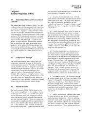
<strong>10</strong>-2. Placement of Hard to Medium Rock<br />
In the infancy of the transition from dumped to compacted<br />
rockfill beginning in the mid-1950’s, several different<br />
methods were used to dump and spread the rock.<br />
In addition, different ideas relative to the maximum rock<br />
size which should be allowed compared with lift thickness<br />
were also evident (Sherard and Cooke 1987). In the last<br />
15 years, the considerable experience gained in construction<br />
and performance of compacted rockfill dams has<br />
resulted in general agreement on these practices for hard<br />
EM 11<strong>10</strong>-2-2301<br />
30 Sep 94<br />
to medium rock (Sherard and Cooke 1987) as discussed<br />
below.<br />
a. The preferred method. The preferred method for<br />
rockfill placement is to dump on the surface of the layer<br />
being placed and then to spread the layer to the desired<br />
thickness with a crawler tractor by pushing the material<br />
over the advancing face of the lift as shown in Figures<br />
<strong>10</strong>-2 and <strong>10</strong>-3. This procedure creates significant<br />
segregation with the larger rocks in the bottom of the lift<br />
and the smaller rock and fines in the upper part. The<br />
main advantage of this technique derives from the relatively<br />
smooth upper surface resulting from pushing the<br />
dumped rock a short distance on top of each layer being<br />
placed such that depressions and voids between larger<br />
rocks become progressively filled with small rocks and<br />
fines. This approach also facilitates maintaining the<br />
desired lift thickness because the dozer operator is always<br />
advancing the lift ahead upon the smooth surface at its<br />
proper elevation. The smooth layer also reduces tire<br />
wear, allows higher truck speeds, and provides a better<br />
surface upon which to operate the vibrating roller.<br />
b. Contrast with past practice. Earlier rockfill<br />
placement practice attempted to avoid segregation of the<br />
rock and/or generation of fines on the lift surface to form<br />
as homogeneous a compacted mass as practicable. The<br />
procedure was to dump the truck loads of rock in piles<br />
spaced upon the surface of the previously compacted lift<br />
and then to spread the piles to form the desired lift thickness.<br />
A very irregular fresh fill surface is created which<br />
makes equipment travel difficult, rapidly wears the rubber<br />
tires, and subjects vibratory rollers to damage because<br />
they do not withstand continuous operation on irregular<br />
surfaces where the drum is pounding on a few high points<br />
of hard rock. This method of rockfill placement is now<br />
considered obsolete by most specialists (Sherard and<br />
Cooke 1987), but is still occasionally proposed.<br />
c. Stratified rockfill is preferred (Sherard and<br />
Cooke 1987). Past practitioners viewed the generation of<br />
stratified rockfill in the placement and compaction operations<br />
to yield undesirable properties with respect to permeability<br />
and compressibility. Considerable experience<br />
with the performance of rockfill dams, whether earth-core<br />
or concrete-faced, has shown that there are no technical<br />
disadvantages to the preferred method of placement in<br />
segregated layers. Sound rock derives its typically adequate<br />
shear strength from a combination of the density of<br />
the upper-lift zone of finer particles and the larger particle<br />
wedging and interlocking in the lower-lift zone rather than<br />
strictly from density. The stratification also assures that<br />
<strong>10</strong>-1
EM 11<strong>10</strong>-2-2301<br />
30 Sep 94<br />
Figure <strong>10</strong>-1. Typical settlement plates (from EM 11<strong>10</strong>-2-1908, Part 2)<br />
any flow through the embankment will move much more<br />
easily in the horizontal direction than in the vertical which<br />
offers downstream slope stability advantages during construction<br />
for a concrete-faced dam if an upstream pool is<br />
impounded during construction or if there is an overtopping<br />
allowance during construction. Even for rockfill<br />
containing considerable fines, the stratified structure<br />
<strong>10</strong>-2<br />
results in a greater average permeability compared with<br />
fill placed to a more homogeneous character.<br />
d. Lift thickness. Lift thicknesses employed in<br />
more recent times for medium to hard rock have averaged<br />
about 1 m (3.3 ft). Cooke (1990) states that the 9.1-Mg
EM 11<strong>10</strong>-2-2301<br />
30 Sep 94<br />
<strong>10</strong>-3
EM 11<strong>10</strong>-2-2301<br />
30 Sep 94<br />
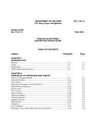
Figure <strong>10</strong>-3. Placing a lift in the Cerrillos Dam test fill<br />
(Note the marking of the previous lift surface with plastic<br />
strips and lime)<br />
(<strong>10</strong>-ton) vibratory roller (Figure <strong>10</strong>-4) has generally<br />
provided excellent results for this thickness. Experience<br />
suggests that selection of lift thickness for sound rock up<br />
to about 1 m (3.3 ft.) is not a particularly critical item<br />
with respect to ability to achieve adequate compaction but<br />
can be based on quarry-run rock size brought to within<br />
the range of lift thicknesses stated above. However, the<br />
use of lift thicknesses approaching or exceeding 1 m<br />
should be on the basis of justification derived from the<br />
test fill. The literature clearly agrees that for sound rock,<br />
quarry-run material can usually be produced to be<br />
satisfactory.<br />
Figure <strong>10</strong>-4. A 9.1 mg (<strong>10</strong>-ton) vibratory roller at work<br />
on the Cerrillos Dam test fill<br />
<strong>10</strong>-4<br />
e. Maximum particle size versus lift thickness. It<br />
has been customary to limit the maximum particle size to<br />
something less than the loose-lift thickness (say, a maximum<br />
of 0.9). However, it has been clearly established<br />
that maximum particle size equal to the lift thickness is<br />
acceptable. With the preferred placement practice, the<br />
vibratory roller will seat these particles among the smaller<br />
rocks and fines. The presence of particles equal in size to<br />
the lift thickness has not been found to result in unacceptably<br />
poor compaction of intervening material, i.e., any<br />
detrimental effects on the compaction or the compressibility<br />
of the fill.<br />
f. Grading. Sound rock is highly segregated in<br />
each lift such that grading of the quarry-run rock is not<br />
important. Cooke (1990) points out that for a given<br />
roller, well-graded quarry-run sound rock will give the<br />
highest density and modulus (lowest compressibility), but<br />
all quarry-run rock, even when poorly graded, has been<br />
satisfactory with respect to embankment performance. He<br />
further states that if the rock is hard, a satisfactory general<br />
specification is “quarry-run rock - the maximum size shall<br />
be that which can be incorporated in the layer and provides<br />
a relatively smooth surface for compaction, not<br />
more than 50 percent shall pass a 2.5-cm (1-in.) sieve,<br />
and not more than 6 percent shall be clay-sized fines.”<br />
Natural gravels with sound particles do not conform to the<br />
typical definition of rockfill but may be considered for<br />
use in the shell of a dam. Loose lift thicknesses for gravels<br />
have ranged between 0.3 and 0.9 m (1 to 3 ft.)<br />
depending on particle size and percentage of minus<br />
U.S. Standard No. 200 sieve sizes (Cooke 1984).<br />
<strong>10</strong>-3. Placement of Soft Rock<br />
Dumped rockfill, which is still used in downstream portion<br />
of sloping-earth-core dams or in the shells of central<br />
earth-core dams, requires sound rock meeting concrete<br />
aggregate specifications. However, very low compressive<br />
strength rock such as possible in siltstones, sandstones,<br />
shists, argillite, and other potentially weak rocks may also<br />
be used as compacted rockfill. This is one of the cost<br />
advantages gained from compacted rockfill as compared<br />
with dumped rockfill in that weak rock formerly wasted<br />
from quarries for dumped rockfill dams became acceptable<br />
materials for even very high compacted<br />
embankments.<br />
a. The preferred method. Soft (weak) rock which<br />
arrives at the test fill containing appreciable fines or<br />
which breaks down significantly in the placement
operations derives its shear strength from density so that it<br />
is generally dumped and spread by crawler tractor directly<br />
on the preceding lift to minimize segregation and yield a<br />
more compact mass. An exception would apply in cases<br />
where the breakage under the crawler tractor alters the fill<br />
from proper classification as rockfill into a soil material<br />
and alternative methods offer the possibility of retaining<br />
satisfactory rockfill traits. This statement assumes that<br />
the determination has been made that the marginal material<br />
placed in a manner retaining rockfill traits will not<br />
deteriorate into a soil material under embankment stresses<br />
or environmental factors.<br />
b. Lift thickness. Because fill composed of soft,<br />
weaker rocks and appreciable fines derives its satisfactory<br />
properties from density, test fill results are likely to show<br />
that thinner lifts (compared with hard, durable rock) on<br />
the order of 0.46 to 0.6 m (18 in. to 2 ft) are required<br />
along with an increase in the number of passes of the<br />
roller from, say, usually 4 for hard rock to 6 or 8 for the<br />
softer, weaker rock. Some breakdown may be desirable<br />
to achieve the desired strength for these materials. The<br />
compacted mass should not exhibit any voids among<br />
larger particles, i.e., the larger particles should be consistently<br />
surrounded by finer material which has clearly been<br />
densified by the compactive effort between and among the<br />
larger particles. The use of water (to be discussed below)<br />
in the compaction of soft rock may result in the test-fill<br />
finding that somewhat thicker lifts can be used.<br />
c. Maximum particle size. Maximum rock size may<br />
be equal to the lift thickness but these sizes will typically<br />
break down during placement and compaction.<br />
d. Grading. Grading of weak rockfill materials is of<br />
no consequence since the procedures, i.e., lift thickness,<br />
compaction, and use of water (to be discussed below) are<br />
adopted to produce some breakdown and high density.<br />
<strong>10</strong>-4. Rockfill Versus Soil<br />
Weak rock introduces the possibility that it will break<br />
down during placement and compaction such that desirable<br />
shear strength and compressibility cannot be achieved<br />
unless it is compacted with water content and density<br />
control using rollers typically employed for soils. In<br />
some cases, the determination that materials will degrade<br />
to such an extent (whether by quarrying, hauling, placement,<br />
and compaction or as the result of environmental<br />
factors such as wetting or air exposure) can be made on<br />
the basis of previous experience, tests on core samples, or<br />
experience gained in the test quarry rather than resulting<br />
EM 11<strong>10</strong>-2-2301<br />
30 Sep 94<br />
from test fill observations. Otherwise, a test fill may be<br />
the only way to make the determination. It is sometimes<br />
possible to maintain the rockfill character of the material<br />
through avoidance of excessive breakage in the fill operations<br />
by processing the quarry-run material to remove<br />
fines and smaller sizes, by using rubber-tired equipment<br />
for the spreading operation, by adjusting roller passes,<br />
weight, or vibration settings, or by a combination of these.<br />
If excessive fines exist in the materials or if they are<br />
generated during compaction, the vibratory roller may be<br />
less effective in compaction compared with the 45.4-Mg<br />
(50-ton) or 68.0 Mg (75-ton) pneumatic roller. In general,<br />
materials which retain the properties to be properly<br />
called rockfill can be brought to satisfactory density using<br />
a vibratory roller. Superior compaction by a pneumatic<br />
roller would probably indicate that the material is more<br />
properly classified as a soil and should be treated as such<br />
in design, construction, and construction control. Perhaps<br />
the key concept distinguishing rockfill from that of soil is<br />
that the rock particles are in contact within the compacted<br />
mass as opposed to “floating” in a “matrix” or “binder” of<br />
soil-sized material (i.e., sands to silts or clays).<br />
<strong>10</strong>-5. Use of Water<br />
The use of water in compaction of rockfill (Figure <strong>10</strong>-5)<br />
is beneficial no matter what the rock quality, but becomes<br />
especially important for types of rocks which exhibit<br />
strength loss upon wetting (usually indicated by low compressive<br />
strength) or whenever there is an appreciable<br />
presence of fines. The use of water in the compaction of<br />
weak rock, whether or not some breakdown is a desirable<br />
end, has been general practice. Indeed, one of the additional<br />
indicators as to whether or not the soft-rock material<br />
retains rockfill properties, is whether or not the<br />
rockfill is strong enough to support hauling equipment<br />
and the vibratory roller when wetted to saturation. If the<br />
equipment becomes immobile, the material ruts more than<br />
several inches under the tires of the trucks, or the added<br />
water stands upon the surface, the material has soil<br />
strength, not rockfill strength. This observational<br />
approach is valid also for hard and medium rock if excessive<br />
fines are present. The application of water has been<br />
on the order of 15 to 20 percent of the volume of the<br />
material. The use of water may represent a serious environmental<br />
factor if drainage from the fill creates turbidity<br />
pollution of the stream or river. Where water use is<br />
restricted for environmental or economic reasons, Cooke<br />
(1984) cites alternative practice of placement of weak<br />
rock in thinner lifts of 0.6 m (2 ft) or less along with an<br />
increase in the number of passes of the vibratory roller.<br />
For any weak rock which exhibits a significant loss of<br />
<strong>10</strong>-5
EM 11<strong>10</strong>-2-2301<br />
30 Sep 94<br />
Figure <strong>10</strong>-5. Applying water prior to lift compaction on<br />
one of the Cerrillos Dam test fills containing appreciable<br />
fines (Note: The operation shown above was an<br />
expedient method for the test fill at the Puerto Rico<br />
damsite. More typically, water is applied from a pressurized<br />
tanker truck with a rear spray bar)<br />
strength for saturated specimens, a saturated test fill<br />
should be conducted to establish placement and compaction<br />
specifications.<br />
<strong>10</strong>-6. Compaction and Compaction Equipment<br />
After the rock has been placed in the desired lift thickness,<br />
the compaction operation is begun. Where surface<br />
settlement readings are to be used to assess densification<br />
(the typical practice), it is advantageous to smooth the<br />
surface of the lift for marking of the settlement grid by<br />
making one complete coverage with the vibratory roller<br />
with the vibrating unit off. The procedure for settlement<br />
readings is addressed in <strong>Chapter</strong> 11. As has been previously<br />
stated, it is important that the compaction operation<br />
be accomplished in a manner to simulate anticipated project<br />
procedures, except for interruptions required to make<br />
measurements and observations. Each pass of the roller,<br />
whether vibratory or rubber-tired pneumatic, should overlap<br />
the previous pass by about 0.3 m (1 ft). Specifics<br />
regarding the vibratory and pneumatic roller are discussed<br />
in the following paragraphs.<br />
a. Vibratory roller. Vibratory rollers (Figure <strong>10</strong>-4<br />
and Appendix B) have evolved considerably since their<br />
inception in the mid-1950’s. It is important for test-fill<br />
designers and field personnel to become familiar with<br />
current manufacturers’ literature and recommendations for<br />
operational speed versus frequency settings to obtain the<br />
most efficient compaction. Appendix B contains recent<br />
information obtained by Los Angeles District pertaining to<br />
<strong>10</strong>-6<br />
these parameters and the specifications they instituted for<br />
Seven Oaks Dam. The amplitude of the roller is the<br />
distance the drum lifts off the ground in its vertical vibration<br />
and the frequency is the number of times per minute<br />
it lifts off the ground (i.e., number of impacts) expressed<br />
as vibrations per minute or VPM. Numerous studies on<br />
distance between successive impact points and centrifugal<br />
force have been conducted over the last 20 years which<br />
have resulted in the establishment of 6 to 8 impacts of the<br />
drum per lineal foot of travel as a minimum for optimal<br />
performance. Appendix B presents a table of VPM versus<br />
impacts per lineal foot for different speeds of operation<br />
of the roller. A modern roller can operate at a<br />
frequency of 1500 to 1800 VPM delivering forces in<br />
excess of 4.1 Mg (9,000 lb) per 0.3 m (1 ft.) of drum<br />
width. Increased frequency translates to increased speeds<br />
of operation which represents construction cost savings.<br />
With increased frequency, a greater force is applied and<br />
more impacts per lineal foot of rolling can take place. As<br />
part of the test fill evaluation objectives, these variables<br />
can be adjusted to provide the optimum rolling procedures<br />
for the given material and offer some latitude to alter the<br />
degree of breakdown if it is a problem.<br />
b. Pneumatic roller. Bertram (1973) suggests<br />
specifications for a 45.4-Mg (50-ton) rubber-tired roller as<br />
follows: “Pneumatic rollers shall have a minimum of four<br />
wheels equipped with pneumatic tires. The tires shall be<br />
of such size and ply as can be maintained at tire pressures<br />
between 552 kPa and 690 kPa (80 and <strong>10</strong>0 psi) for a<br />
11.3-Mg (25,000-lb) wheel load during rolling operations.<br />
The roller wheels shall be located abreast and shall be<br />
designed so that each wheel will carry approximately<br />
equal load in traversing uneven ground. The spacing of<br />
the wheels shall be such that the distance between the<br />
nearest edges of adjacent tires will not be greater than<br />
50 percent of the width of a single tire at the operating<br />
pressure for a 11.3-Mg (25,000-lb) wheel load. The<br />
equipment shall be subject to the approval of the contracting<br />
officer.” Pneumatic rollers should be towed or operated<br />
at speeds less than 8 kmph (5 mph). Heavier<br />
pneumatic rollers are now available and should be considered<br />
as applicable but documentation of their use on rock<br />
test fills has not been discovered. For most test fills, the<br />
optimum performance of either a pneumatic or vibratory<br />
roller has been achieved in 8 passes or less. Typically,<br />
the compaction program for any given lift thickness has<br />
been to schedule a maximum of 8 passes (lift coverages)<br />
with interruptions between each two passes for measurements<br />
and observations. After compaction of a given lift<br />
has been completed and all tests and measurements have<br />
been made, the surface of the completed lift may be covered<br />
with a marker material such as lime or a heavy
plastic membrane (0.02 cm or 8 mil maximum thickness)<br />
as shown in Figure <strong>10</strong>-3 to facilitate identification of<br />
individual lifts within an inspection trench or pit after the<br />
EM 11<strong>10</strong>-2-2301<br />
30 Sep 94<br />
entire test fill is complete. Inspection trenches or pits will<br />
be discussed in <strong>Chapter</strong> 11.<br />
<strong>10</strong>-7