FIRE HYDRANT LAYOUT, SPACING, AND TESTING ...
FIRE HYDRANT LAYOUT, SPACING, AND TESTING ...
FIRE HYDRANT LAYOUT, SPACING, AND TESTING ...

You also want an ePaper? Increase the reach of your titles
YUMPU automatically turns print PDFs into web optimized ePapers that Google loves.
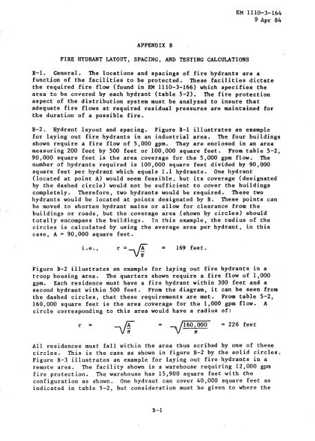
<strong>FIRE</strong> <strong>HYDRANT</strong> <strong>LAYOUT</strong>, <strong>SPACING</strong>, <strong>AND</strong> <strong>TESTING</strong> CALCULATIONS<br />
B-1 . General . The locations and spacings of fire hydrants are a<br />
function of the facilities to be protected . These facilities dictate<br />
the required fire flow (found in EM 1110-3-166) which specifies the<br />
area to be covered by each hydrant (table 5-2) . The fire protection<br />
aspect of the distribution system must be analyzed to insure that<br />
adequate fire flows at required residual pressures are maintained for<br />
the duration of a possible fire .<br />
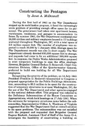
B-2 . Hydrant layout and spacing . Figure B-1 illustrates an example<br />
for laying out fire hydrants in an industrial area . The four buildings<br />
shown require a fire flow of 5,000 gpm . They are enclosed in an area<br />
measuring 200 feet by 500 feet or 100,000 square feet . From table 5-2,<br />
90,000 square feet is the area coverage for the 5,000 gpm flow . The<br />
number of hydrants required is 100,000 square feet divided by 90,000<br />
square feet per hydrant which equals 1 .1 hydrants . One hydrant<br />
(located at point A) would seem feasible, but its coverage (designated<br />
by the dashed circle) would not be sufficient to cover the buildings<br />
completely . Therefore, two hydrants would be required . These two<br />
hydrants would be located at points designated by B . These points can<br />
be moved to shorten hydrant mains or allow for clearance from the<br />
buildings or roads, but the coverage area (shown by circles) should<br />
totally encompass the buildings . In this example, the radius of .the<br />
circles is calculated by using the average area per hydrant, in this<br />
case, A = 90,000 square feet .<br />
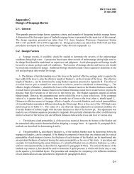
Figure B-2 illustrates an example for laying out fire hydrants in a<br />
troop housing area . The quarters shown require a fire flow of 1,000<br />
gpm . Each residence must have a fire hydrant within 300 feet and a<br />
second hydrant within 500 feet . From the diagram, it can be seen from<br />
the dashed circles, that these requirements are met . From table 5-2,<br />
160,000 square feet is the area coverage for the 1,000 gpm flow . A<br />
circle corresponding to this area would have a radius of :<br />
r<br />
APPENDIX B<br />
i .e ., r = -VA = 169 feet .<br />
= 160,000 = 226 feet<br />
x<br />
EM 1110-3-164<br />
9 Apr 84<br />
All residences must fall within the area thus scribed by one of these<br />
circles . This is the case as shown in figure B-2 by the solid circles .<br />
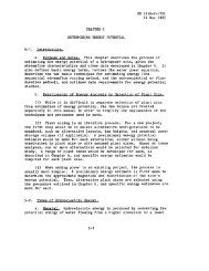
Figure B-3 illustrates an example for laying out fire hydrants in a<br />
remote area . The facility shown is a warehouse requiring 12,000 gpm<br />
fire protection . The warehouse has 15,900 square feet with the<br />
configuration as shown . One hydrant can cover 40,000 square feet as<br />
indicated in table 5-2, but consideration must be given to where the
EM 1110-3-164<br />
9 Apr 84<br />
w 0<br />
U . S . ATmy Corps of Engineers<br />
<strong>HYDRANT</strong> MAIN (TYP)<br />
SCALE* 1 INCH =100 FEET<br />
FIGURE B-l . <strong>FIRE</strong> <strong>HYDRANT</strong> <strong>LAYOUT</strong> FOR AN INDUSTRIAL AREA
0<br />
U . S . Army Corps of Engineers<br />
SCALE : 1 INCH= 100 FEET<br />
B- 3<br />
EM 1110-3-164<br />
9 Apr 84<br />
0<br />
FIGURE B-2 . <strong>FIRE</strong> <strong>HYDRANT</strong> <strong>LAYOUT</strong> FOR A TROOP HOUSING AREA
EM 1110-3-164<br />
9 Apr 84<br />
LIMIT LINE FOR<br />
<strong>FIRE</strong> <strong>HYDRANT</strong><br />
<strong>HYDRANT</strong> MAIN (TYR)<br />
U . S . Army Corps of Engineers<br />
SCALE : 1 INCH = 100 FEET<br />
FIGURE B-3 . <strong>FIRE</strong> <strong>HYDRANT</strong> <strong>LAYOUT</strong> FOR A REMOTE FACILITY
hydrants must be placed . A minimum 25 feet clearance must be kept from<br />
the building, demonstrated by the dashed lines . A circle with area of .<br />
40,000 square feet would have a radius of 113 feet . Hydrants must be<br />
placed so that circles scribed by this radius encompass the entire<br />
warehouse . Given these constraints, three fire hydrants at the<br />
locations A, B, and C shown in figure B-2 must be provided . These<br />
points can be adjusted slightly to clear traffic and roadways, but the<br />
coverage area for each hydrant should totally encompass the building<br />
the hydrant is protecting . Figure B-4 illustrates an example for<br />
laying out fire hydrants in a combined industrial and troop housing<br />
area . The fire flows required would be determined from EM 1110-3-166,<br />
but for example purposes, are assumed as follows :<br />
Facility<br />
Required fire flow<br />
The coverage area per hydrant figures are from table 5-2 and the radii<br />
of coverage circles have been calculated in the same manner as in the<br />
previous examples . In the diagram, the circles represent the coverage<br />
areas for each particular fire demand . The radii vary since the<br />
coverage areas decrease with the increasing fire demand . The circle<br />
related to a particular demand must encompass the structures creating<br />
this fire demand . An exception would be when another circle of higher<br />
demand already covers the building or structure in question ., For<br />
example, hydrant B, designed to protect the Mess Hall, also protects<br />
the P-X . The P-X has a lesser fire demand than the Mess Hall .<br />
Therefore, a hydrant explicitly for the P-X is unnecessary. Similarly,<br />
a portion of the garages is protected by hydrant E-2 . Hydrants A-1 and<br />
A-2 protect the troop housing area, hydrants C-1, C-2, and C-3 protect<br />
the machine shop area ; hydrant D protects the remainder of the garage<br />
area, and hydrants E-1 and E-2 protect the P .O .L . area . The layout<br />
plan of fire hydrants is optimal when all buildings and structures are<br />
covered and when the overlap$ among the various circles are minimized .<br />
The minimization of the overlap area would tend to reduce the number of<br />
redundant fire hydrants . . There are several restraints or restrictions<br />
which must be taken into consideration . All hydrants must be kept a<br />
minimum of 25 feet, preferably 50 feet, from the facility it is to<br />
protect . There must be one fire hydrant within 300 feet and another<br />
within 500 feet of any particular barracks or living quarters . Hydrant<br />
mains should be kept as short as possible . The layout presented is not<br />
the only possible solution ; other configurations are possible . Sound<br />
B- 5<br />
Coverage area<br />
per hydrant<br />
-(feet) ^<br />
Radius of<br />
coverage<br />
circle<br />
(feet)<br />
Troop housing 1,000 160,000 226<br />
P-X 3,000 120,000 195<br />
Mess hall 4,500 95,000 174<br />
Machine shops 5,000 90,000 169<br />
Garages 8',000 60,000 138<br />
P .O .L . 12,000 40,000 113<br />
EM 1110-3-164<br />
9 Apr 84
EM 1110-3-164<br />
9 Apr 84<br />
SCALE : 1 INCH = 100 FEET<br />
U . S . Army Corps of Engineers<br />
FIGURE B-4 . <strong>FIRE</strong> <strong>HYDRANT</strong> <strong>LAYOUT</strong> FOR COMBINED INDUSTRIAL <strong>AND</strong> HOUSING AREAS<br />
B-6<br />
W<br />
Ocrc<br />
O C'<br />
O<br />
N
EM 1110-3-164<br />
9 Apr 84<br />
judgment and actual field conditions must be applied for a proper<br />
layout design .