


Create successful ePaper yourself
Turn your PDF publications into a flip-book with our unique Google optimized e-Paper software.
5 Circuit description<br />
5.1 General<br />
The microprocessor used in the <strong>Electron</strong> is a 6502A with the clock signals provided by a 16MHz crystal oscillator (IC8) in<br />
conjunction with divider circuitry in the ULA (IC1). The 6502 runs at three speeds depending on what is being accessed:<br />
2MHz: The processor will run at 2MHz during an access cycle to the ROM. This is because the ROM is being accessed only<br />
by the processor which has a maximum speed of 2MHz.<br />
1MHz: The processor will run at 1MHz during an access cycle to the RAM. The processor and the video are competing for<br />
access to the RAM, and the RAM can only support a bandwidth of 2MHz. In screen modes 4, 5 and 6 this is no problem since<br />
the screen only needs 1MHz access to the RAM.<br />
Stopped: In screen modes 0, 1, 2 and 3 the screen uses all the available memory time slots during the display period. The<br />
processor is denied RAM access during 40 microseconds of each 64 microseconds of the 256 lines in 312 which is the display<br />
period, and it is made to wait for RAM access until the end of the period.<br />
Random Access (read/write) Memory on the <strong>Electron</strong> is provided by four 64Kbit dynamic memory devices (ICs 4 to 7), giving<br />
32Kbytes in all. This means that to read a byte from memory requires two accesses. IC4 contains bit 0 and bit 1, IC5 contains<br />
bit 2 and bit 3, IC6 contains bit 4 and bit 5, and IC7 contains bit 6 and bit 7. The mechanism for doing this is handled by the<br />
ULA.<br />
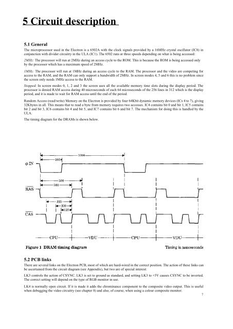
The timing diagram for the DRAMs is shown below.<br />
5.2 PCB links<br />
There are several links on the <strong>Electron</strong> PCB, most of which are hard-wired in the correct position. The action of these links can<br />
be ascertained from the circuit diagram (see Appendix), but two are of special interest:<br />
LK3 controls the action of CSYNC. LK3 is set to ground as standard, and setting LK3 to +5V causes CSYNC to be inverted.<br />
The correct setting will depend on the type of RGB monitor in use.<br />
LK4 is normally open circuit. If it is made it adds the chrominance component to the composite video output. This is useful<br />
when debugging the video circuitry (see chapter 8) and also, of course, when using a colour composite monitor.<br />
7


