


Create successful ePaper yourself
Turn your PDF publications into a flip-book with our unique Google optimized e-Paper software.
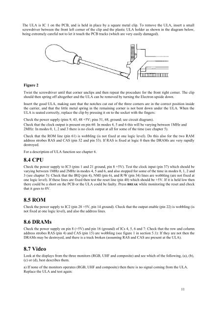
The ULA is IC 1 on the PCB, and is held in place by a square metal clip. To remove the ULA, insert a small<br />
screwdriver between the front left corner of the clip and the plastic ULA holder as shown in the diagram below,<br />
being extremely careful not to let it touch the PCB tracks (which are very easily damaged).<br />
Figure 2<br />
Twist the screwdriver until that corner unclips and then repeat the procedure for the front right corner. The clip<br />
should then spring off altogether and the ULA can be removed by turning the <strong>Electron</strong> upside down.<br />
Insert the good ULA, making sure that the notches cut out of the three corners are in the correct position inside<br />
the carrier, and that the little metal spring in the remaining corner is not bent down under the ULA. When the<br />
ULA is seated correctly, replace the clip by pressing it on to the socket with the fingers:<br />
Check the power supply (pins 9, 43, 48 +5V; pins 51, 68, ground; see circuit diagram).<br />
Check that the clock output is present on pin 60. In modes 4, 5 and 6 this will be varying between 1MHz and<br />
2MHz: In modes 0, 1, 2 and 3 there is no clock output at all for some of the time (see chapter 5).<br />
Check that the ROM line (pin 61) is wobbling (is not fixed at one logic level). Do this also for the two RAM<br />
address strobes RAS and CAS (pin 52 and pin 53). If RAS is fixed at logic 0 then the DRAMs are very rapidly<br />
destroyed.<br />
For a description of ULA function see chapter 6.<br />
8.4 CPU<br />
Check the power supply to IC3 (pins 1 and 21 ground, pin 8 +5V). Test the clock input (pin 37) which should be<br />
varying between 1MHz and 2MHz in modes 4, 5 and 6, and also stopped for some of the time in modes 0, 1, 2 and<br />
3 (see chapter 5): Check that the IRQ (pin 4), NMI (pin 6), and R/W (pin 34) lines are wobbling (are not fixed at<br />
one logic level). If these lines are fixed then test the reset line (pin 40) which should be +5V. If it is held low then<br />
there could be a short on the PCB or the ULA could be faulty. Press BREAK while monitoring the reset and check<br />
that it goes to 0V.<br />
8.5 ROM<br />
Check the power supply to IC2 (pin 28 +5V, pin 14 ground). Check that the output enable (pin 22) is wobbling (is<br />
not fixed at one logic level), and also the address lines.<br />
8.6 DRAMs<br />
Check the power supply on pin 8 (+5V) and pin 16 (ground) of ICs 4, 5, 6 and 7: Check that the row and column<br />
address strobes RAS (pin 4) and CAS (pin 15) are wobbling (see figure 1 in section 5.1): If they are not then the<br />
DRAMs may be destroyed, and there is a track broken (assuming RAS and CAS are present at the ULA).<br />
8.7 Video<br />
Look at the displays from the three monitors (RGB, UHF and composite) and see which of the following, (a), (b),<br />
(c) or (d), best describes them.<br />
a) If none of the monitors operates (RGB, UHF and composite) then there is no signal coming from the ULA.<br />
Replace the ULA and test again:<br />
11


