80-MHz Balanced Photoreceivers
80-MHz Balanced Photoreceivers
80-MHz Balanced Photoreceivers

You also want an ePaper? Increase the reach of your titles
YUMPU automatically turns print PDFs into web optimized ePapers that Google loves.
USER’S GUIDE<br />
<strong>80</strong>-<strong>MHz</strong> <strong>Balanced</strong><br />
<strong>Photoreceivers</strong><br />
Model 18X7<br />
2584 Junction Ave. • San Jose, CA 95134-1902 • USA<br />
phone: (408) 919–1500<br />
e-mail: contact@newfocus.com • www.newfocus.com
Warranty<br />
New Focus, Inc. guarantees its products to be free of defects for one year from<br />
the date of shipment. This is in lieu of all other guarantees, expressed or implied,<br />
and does not cover incidental or consequential loss.<br />
Information in this document is subject to change without notice.<br />
Copyright 2003, New Focus, Inc. All rights reserved.<br />
The logo and NEW FOCUS, Inc. are registered trademarks of<br />
NEW FOCUS, Inc.<br />
Document Number 181710 Rev. A
Contents<br />
Introduction 5<br />
Overview . . . . . . . . . . . . . . . . . . . . . . . . . . . . . . . . . . . 5<br />
Quick Start . . . . . . . . . . . . . . . . . . . . . . . . . . . . . . . . . 5<br />
General Principles . . . . . . . . . . . . . . . . . . . . . . . . . . . 7<br />
Customer Service 11<br />
Technical Support . . . . . . . . . . . . . . . . . . . . . . . . . . 11<br />
Service . . . . . . . . . . . . . . . . . . . . . . . . . . . . . . . . . . . . . 11<br />
Specifications 12<br />
<strong>80</strong>-<strong>MHz</strong> <strong>Balanced</strong> <strong>Photoreceivers</strong> Contents • 3
4 • Contents NEW FOCUS, Inc.
Introduction<br />
Overview<br />
Quick Start<br />
The New Focus Model 18X7 balanced photoreceiver<br />
consists of two matched photodiodes and a highspeed<br />
amplifier that generates an output voltage<br />
proportional to I 2 - I 1 , the difference between the<br />
photocurrents in the two photodiodes.<br />
The Quick Start and General Principles sections below<br />
give an overview of setting up the photoreceiver and<br />
understanding its principles and design. The sections<br />
that follow give detailed information about the<br />
technical specifications.<br />
The following parts are supplied with the<br />
Model 18X7 balanced photoreceiver:<br />
• Model 0923 M8B-to-M8B connector power cable<br />
• Model 0924 M8B-to-banana plug power cable<br />
• Model 1225 SMA-to-BNC adapter<br />
The steps below describe the basics of setting up and<br />
using the photoreceiver.<br />
1. Use one of the supplied power cables to connect<br />
the photoreceiver to a ±15-volt power source that<br />
can supply 200 mA (the minimum current<br />
requirement for DC power supply is 100mA).<br />
<strong>80</strong>-<strong>MHz</strong> <strong>Balanced</strong> <strong>Photoreceivers</strong> Introduction • 5
Note:<br />
For the New Focus Model 0901 power supply, use<br />
the 0923 M8B-to-M8B cable. For other power<br />
supplies, use the 0924 M8B-to-banana plug power<br />
cable.<br />
When using the M8B-to-banana plug cable, take care to<br />
hook up the banana plugs as follows to avoid damaging<br />
the photoreceiver: Red = +15 V, Black = -15 V, Green =<br />
Ground.<br />
2. Mount the photoreceiver to your optical table.<br />
3. Connect the optical source to both optical inputs.<br />
For the Model 1<strong>80</strong>7, it is possible to align a small<br />
free-space beam through the FC adapter, onto the<br />
1x0.84 mm 2 photodiode. The Model 1817 has a<br />
much smaller diode (0.1 mm active area diameter),<br />
and we do not recommend use with free-space<br />
beams. The FC adapter for both types of 18X7<br />
photoreceiver will accommodate either multimode<br />
or single-mode fiber.<br />
To prevent saturation of the amplifier, keep the difference<br />
between the input powers less than the saturation power<br />
shown in Specifications.<br />
The optical power must remain below the absolute<br />
maximum power listed in Specifications. Exceeding<br />
the maximum power may damage the photodiode<br />
and the amplifier.<br />
4. Individually block each photodiode input to check<br />
and adjust the optical inputs so that the output<br />
voltages are in the desired –2.5 to +2.5 V range<br />
(with 50 Ω load).<br />
Illuminate both diodes simultaneously and use the<br />
output to fine-tune the optical power balance<br />
between the two diodes while observing voltage<br />
on a digital voltmeter or other low-frequency<br />
measurement device.<br />
6 • Introduction NEW FOCUS, Inc.
5.<br />
General Principles<br />
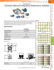
Figure 1:<br />
Functional<br />
block diagram<br />
of the<br />
Model 18X7<br />
Figure 2:<br />
Mechanical<br />
drawing of the<br />
balanced<br />
photoreceiver<br />
Finally, connect the output SMA connector to the<br />
desired load or instrument via a 50-Ω<br />
coaxial<br />
cable.<br />
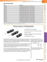
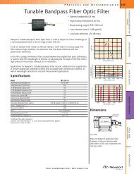
The New Focus Model 18X7 balanced photoreceiver<br />
consists of two matched photodiodes and a highfrequency<br />
amplifier that generates an output voltage<br />
proportional to I2<br />
- I1,<br />
the difference between the<br />
photocurrents in the two photodiodes. Figure 1 shows<br />
a functional block diagram of the balanced photoreceiver,<br />
and Figure 2 shows the mechanical drawing.<br />
D2<br />
D1<br />
+V<br />
-V<br />
TIA OP AMP<br />
<strong>80</strong>-<strong>MHz</strong> <strong>Balanced</strong> <strong>Photoreceivers</strong> Introduction • 7<br />
OUTPUT<br />
Unless otherwise noted, dimensions are in inches with metric dimensions in mm in brackets.
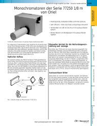
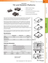
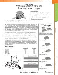
Figure 3:<br />
Typical<br />
responsivities<br />
of the Silicon<br />
and InGaAs PIN<br />
photodiodes in<br />
Model1<strong>80</strong>7<br />
(top) and<br />
Model 1817<br />
(bottom)<br />
Responsivity and Input Power<br />
The Model 1<strong>80</strong>7 uses a matched pair of silicon<br />
photodiodes, while the Model 1817 uses a matched<br />
pair of InGaAs photodiodes. Figure 3 shows the<br />
typical responsivity of the photodiodes.<br />
Responsivity, A/W<br />
Responsivity, A/W<br />
0.60<br />
0.40<br />
0.20<br />
0.00<br />
1<br />
0.8<br />
0.6<br />
0.4<br />
0.2<br />
200 400 600 <strong>80</strong>0 1000 1200<br />
Wavelength, nm<br />
0<br />
<strong>80</strong>0 1000 1200 1400 1600 1<strong>80</strong>0<br />
Wavelength, nm<br />
Gain, Bandwidth and Noise<br />
The amplifier is a low-noise device with low output<br />
impedance. The amplifier’s transimpedance gain is 40<br />
V/mA.<br />
Depending on wavelength (see typical responsivity<br />
curves in Figure 3), the amplifier will reach saturation<br />
levels when the difference between the two photo<br />
inputs is approximately 110 mW (for responsivity of<br />
0.5 A/W). For a high-impedance load, the maximum<br />
output voltage will be approximately ±4 V before the<br />
8 • Introduction NEW FOCUS, Inc.
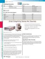
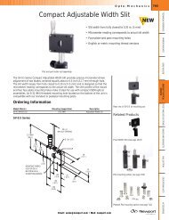
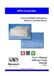
Figure 4:<br />
Model1<strong>80</strong>7<br />
typical<br />
frequency<br />
response (top)<br />
and noise<br />
spectrum<br />
(bottom) (NEP<br />
at minimum of<br />
noise floor is<br />
3.3 pW/ √Hz.<br />
)<br />
Figure 5:<br />
Model1817<br />
typical<br />
frequency<br />
response (top)<br />
and noise<br />
spectrum<br />
(bottom) (NEP<br />
at minimum of<br />
noise floor is<br />
2.5 pW/ √Hz.)<br />
amplifier is saturated. For a 50-Ω<br />
load, the maximum<br />
output voltage will be approximately ±2 V before<br />
saturation.<br />
The 3-dB bandwidth is typically in excess of <strong>80</strong> <strong>MHz</strong><br />
for the Model 18X7 photoreceivers. Note that 3-dB<br />
bandwidths as high as 120 <strong>MHz</strong> for both models are<br />
not uncommon. Figures 4 and 5 show typical<br />
frequency responses for the two photoreceivers.<br />
10 dB/Div<br />
10dB/Div<br />
0 20 40 60<br />
Frequency (<strong>MHz</strong>)<br />
<strong>80</strong> 100 120<br />
0 20 40 60<br />
Frequency (<strong>MHz</strong>)<br />
<strong>80</strong> 100 120<br />
Figures 4 and 5 also show the typical noise spectrum.<br />
Model 1<strong>80</strong>7 has a minimum noise-equivalent power<br />
(NEP) of 3.3 pW/ √Hz<br />
from DC-10<strong>MHz</strong>. NEP versus<br />
frequency is shown in Figure 4.<br />
For Model 1817, minimum NEP is 2.5 pW/ √Hz<br />
from<br />
DC-10<strong>MHz</strong>, and NEP versus frequency is shown in<br />
<strong>80</strong>-<strong>MHz</strong> <strong>Balanced</strong> <strong>Photoreceivers</strong> Introduction • 9
Figure.5. Therefore, the integrated noise from DC-<br />
<strong>80</strong><strong>MHz</strong> is 502 nWrms<br />
for Model 1<strong>80</strong>7 and 376 nWrms<br />
for Model 1817. This input optical noise level is the<br />
approximate minimum optical signal that can be<br />
detected with these photoreceivers.<br />
To detect a weaker signal, you can reduce the noise by<br />
adding an electronic bandpass filter at the output of<br />
the photoreceiver, or consider the 125 kHz bandwidth<br />
Nirvana Auto-balanced Photoreceiver, Model 20X7, or<br />
use lock-in amplifier and chopper techniques to<br />
further narrow your measurement bandwidth.<br />
10 • Introduction NEW FOCUS, Inc.
Customer Service<br />
Technical Support<br />
Service<br />
Information and advice about the operation of any<br />
New Focus product is available from our technical<br />
support engineers.<br />
Engineers are on duty from 8:00–5:00 PST, Monday<br />
through Friday (excluding holidays). For quickest<br />
response, ask for “Technical Support” and know the<br />
model number of your photoreceiver.<br />
Phone: (408) 919-1500<br />
Fax: (408) 9<strong>80</strong>-8883<br />
Support is also available by email:<br />
techsupport@newfocus.com<br />
We typically respond to email within one business day.<br />
In the event that your photoreceiver malfunctions or<br />
becomes damaged, please contact New Focus for a<br />
return authorization number and instructions on<br />
shipping the unit back for evaluation and repair.<br />
<strong>80</strong>-<strong>MHz</strong> <strong>Balanced</strong> <strong>Photoreceivers</strong> Customer Service • 11
Specifications<br />
Model 1<strong>80</strong>7 Model 1817<br />
Wavelength Range 300–1050 nm 900–1700 nm<br />
3-dB Bandwidth DC–<strong>80</strong> <strong>MHz</strong> DC–<strong>80</strong> <strong>MHz</strong><br />
Common Mode Rejection Ratio 25 dB typical 25 dB typical<br />
Conversion Gain 2x10⁴<br />
V/W 4x10⁴<br />
V/W<br />
Typical Max. Responsivity 0.5 A/W 1.0 A/W<br />
Transimpedance Gain 4x10⁴<br />
V/A 4x10⁴<br />
V/A<br />
Output Impedance 50 Ω<br />
Minimum NEP<br />
CW Saturation Power<br />
(Differential) (mW)<br />
Max. Differential Power<br />
(Damage Threshold) (mW)<br />
Max. Power per Photodiode<br />
(Damage Threshold) (mW)<br />
50 Ω<br />
3.3 pW/ √Hz<br />
2.5 pW/ √Hz<br />
110 @ <strong>80</strong>0 nm 55 @ 1550 nm<br />
10 @ <strong>80</strong>0 nm 5 @ 1550 nm<br />
10 @ <strong>80</strong>0 nm 5 @ 1550 nm<br />
Detector Material/Type Si/PIN InGaAs/PIN<br />
Detector Active Area 1.01mm x 0.83 mm 0.1 mm diameter<br />
Optical Input FC FC<br />
Electrical Output SMA SMA<br />
Package Dimension 3.00 x 2.86 x 2.07<br />
inches<br />
Power Supply Requirement ± 15 V DC,