


Create successful ePaper yourself
Turn your PDF publications into a flip-book with our unique Google optimized e-Paper software.
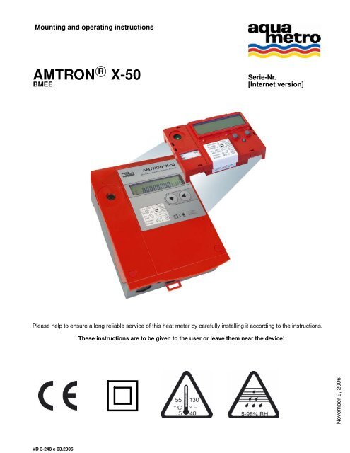
Mounting and operating instructions<br />
<strong>AMTRON</strong> R○ X-<strong>50</strong> Serie-Nr.<br />
BMEE [Internet version]<br />
Please help to ensure a long reliable service of this heat meter by carefully installing it according to the instructions.<br />
VD 3-248 e 03.2006<br />
These instructions are to be given to the user or leave them near the device!<br />
M10000def.doc<br />
9, 2006<br />
November
Mounting and operating instructions <strong>AMTRON</strong> R○ X-<strong>50</strong><br />
Contents<br />
Intended use . . . . . . . . . . . . . . . . . 3<br />
Installation instruction . . . . . . . . . . . . . . . 3<br />
View of the unit . . . . . . . . . . . . . . . . . 8<br />
Operating instructions . . . . . . . . . . . . . . . 9<br />
Display . . . . . . . . . . . . . . . . . 9<br />
Operating modes . . . . . . . . . . . . . . . . 9<br />
Explanations . . . . . . . . . . . . . . . . . 10<br />
Main loop . . . . . . . . . . . . . . . . . . 11<br />
INFO loop (Information) . . . . . . . . . . . . . . . 12<br />
Instant loop . . . . . . . . . . . . . . . . . 12<br />
Time loop . . . . . . . . . . . . . . . . . . 13<br />
Stich loop (billing date) . . . . . . . . . . . . . . . 13<br />
Logger loop . . . . . . . . . . . . . . . . . 14<br />
Inputs loop . . . . . . . . . . . . . . . . . 14<br />
Units loop . . . . . . . . . . . . . . . . . . 16<br />
M-Bus loop . . . . . . . . . . . . . . . . . 18<br />
CONFIG loop (Configuration) . . . . . . . . . . . . . . 18<br />
System loop . . . . . . . . . . . . . . . . . 20<br />
Editing methods . . . . . . . . . . . . . . . . 20<br />
Number entry . . . . . . . . . . . . . . . . 20<br />
Date entry . . . . . . . . . . . . . . . . . 21<br />
Time entry . . . . . . . . . . . . . . . . . 21<br />
Commissioning . . . . . . . . . . . . . . . . 21<br />
Commissioning . . . . . . . . . . . . . . . . 21<br />
Function control . . . . . . . . . . . . . . . . 21<br />
Error messages, alarms . . . . . . . . . . . . . . . 22<br />
Data back-up . . . . . . . . . . . . . . . . . 22<br />
Recalibration/auditing . . . . . . . . . . . . . . . 22<br />
Procedure . . . . . . . . . . . . . . . . . 22<br />
Audit modules . . . . . . . . . . . . . . . . 23<br />
Technical data . . . . . . . . . . . . . . . . . 23<br />
Mounting template . . . . . . . . . . . . . . . . 27<br />
VD 3-248 e 03.2006 2 Aquametro AG
<strong>AMTRON</strong> R○ X-<strong>50</strong> Mounting and operating instructions<br />
Intended use<br />
The device is to be used in dry interior areas. For applications in Ex areas or in contact with water or other liquids no<br />
liability can be assumed.<br />
Installation instruction<br />
The installation may only be carried out by authorised experts in accordance with valid regulations (EN1434 Part 6 Regulations<br />
and Recommendations for Installation and Operation) and/or the recommendations of specialist organisations<br />
(such as the AGFW series Codes of Practice for District Heating.<br />
Important:<br />
The totaliser, the paired sensors and the flow meter of a measuring point are to be compatible with one another<br />
and should not be replaced.<br />
Verified instruments are lead sealed. These seals should not be damaged or broken in any way.<br />
Measuring instruments have to be treated with caution. To protect from damage and contamination, the packing should<br />
be removed just before installation.<br />
Verify, if the sensor (e.g. Pt<strong>50</strong>0) is suitable for the calculator. Pay attention to the correct installation side (warm<br />
side, cold side) of the flow meter.<br />
Verify the pulse value of the flow meter and the totaliser according to the labels. Pay attention to the flow direction<br />
of the flow meter.<br />
Verifiable parameters or other service parameters can only be changed in the field if the instrument is not a verified unit.<br />
Documentation is available on request.<br />
Aquametro AG 3 VD 3-248 e 03.2006
Mounting and operating instructions <strong>AMTRON</strong> R○ X-<strong>50</strong><br />
Scope of supply; needed mounting material and tools<br />
1) Option<br />
Open casing<br />
VD 3-248 e 03.2006 4 Aquametro AG
<strong>AMTRON</strong> R○ X-<strong>50</strong> Mounting and operating instructions<br />
Mounting on DIN rail (Mounting template, see attachment)<br />
Mounting on flat wall (Mounting template, see attachment)<br />
Aquametro AG 5 VD 3-248 e 03.2006
Mounting and operating instructions <strong>AMTRON</strong> R○ X-<strong>50</strong><br />
Terminal assignments see inside cover<br />
Terminal assignments<br />
VD 3-248 e 03.2006 6 Aquametro AG
<strong>AMTRON</strong> R○ X-<strong>50</strong> Mounting and operating instructions<br />
Connect signal cables and where appropriate connect the low voltage supply<br />
Close cover Remove sealing studs<br />
These instructions are to be given to the user or leave them near the device!<br />
Aquametro AG 7 VD 3-248 e 03.2006
Mounting and operating instructions <strong>AMTRON</strong> R○ X-<strong>50</strong><br />
View of the unit<br />
0. Cover<br />
1. Liquid Crystal Display (LCD)<br />
2. Enter key<br />
3. Select key<br />
4. Sight glass, if verified with calibration mark<br />
5. Optical M-Bus interface<br />
6. Service key<br />
7. Programming key under seal<br />
8. Nameplate of totaliser module<br />
9. Cover screws (under sealing studs)<br />
10. Mounting holes<br />
11. Clip-on holder for rail mounting<br />
12. Cover hinge<br />
13. Plug-in totaliser module<br />
14. Connector module<br />
15. Cable entry Ø12 mm with plastic seal<br />
16. Cable entry Ø16 mm with plastic seal<br />
17. Options module<br />
VD 3-248 e 03.2006 8 Aquametro AG
<strong>AMTRON</strong> R○ X-<strong>50</strong> Mounting and operating instructions<br />
Operating instructions<br />
Display<br />
1. Tag, 3 characters<br />
2. Numerical display with 8 large characters<br />
3. Decimal point numbers are highlighted within a frame<br />
4. Units<br />
5. Unit in User Mode<br />
6. Unit in Service Mode<br />
7. Edit Mode: displayed values can be altered<br />
8. Alarm<br />
9. No function<br />
10. Flow display, flashes when flow is registered<br />
11. Symbol for values in memory (billing date or logger)<br />
12. Select key<br />
13. Enter key<br />
Operating modes<br />
With the operating keys all relevant settings (depending the Operating mode) to be carried out.<br />
User Mode:<br />
When the housing is closed, freely accessible data can be shown in the display using the keys. Service Mode:<br />
This can be activated by pressing the service key when the cover is open. It also enables all necessary but non-verifiable<br />
start-up parameters to be set and displayed.<br />
Programming Mode:<br />
This can be activated only if the factory seal has been destroyed. This enables the complete range of settings, including<br />
calibrated values to be made.<br />
Aquametro AG 9 VD 3-248 e 03.2006
Mounting and operating instructions <strong>AMTRON</strong> R○ X-<strong>50</strong><br />
Explanations<br />
S-Edit<br />
P-Edit<br />
E 12345678 kWh<br />
INFO<br />
E 12345.678 kWh<br />
E 12.345678 kWh<br />
Prog<br />
Prog<br />
Edit<br />
Memory<br />
Press Select key<br />
Press Enter key<br />
Press Service key<br />
Press Programming key (under seal)<br />
Unit in User Mode<br />
Unit in Service Mode<br />
Unit in Program Mode, only possible if the seal is<br />
destroyed<br />
Example for a display<br />
Display under certain conditions<br />
Unit in Edit Mode<br />
Display of logger data and billing readings<br />
Press Select and Enter keys simultaneously:<br />
3 more decimal places will be shown<br />
Edit in Service Mode:<br />
- Press Service key<br />
- Press Enter key<br />
- Entry according to type of data<br />
Edit in Programming Mode:<br />
- Press Service key<br />
- Press Enter key<br />
- Entry according to type of data<br />
VD 3-248 e 03.2006 10 Aquametro AG
<strong>AMTRON</strong> R○ X-<strong>50</strong> Mounting and operating instructions<br />
Main loop<br />
The main loop shows the most important readings and provides access to subloops.<br />
High accurate readings can also be displayed when both keys are pressed simultaneously.<br />
The meter readings of the calculator can be adjusted to external counters in Service- or Program-Mode. Changes in<br />
Program-Mode can only be changed if the instrument is not a verified unit.<br />
E 12345678 kWh<br />
V 12345678 m3<br />
H2 12345 .678 m3<br />
H3 12345 .678 m3<br />
ImP 100 L<br />
Sid cold<br />
INFO<br />
InStAnt<br />
tIME<br />
Stich<br />
LOGGEr<br />
InPutS<br />
OutPutS<br />
UnitS<br />
M-bUS<br />
CONFIG<br />
SYStEM<br />
LCD<br />
Test<br />
/<br />
P-Edit<br />
/ P-Edit<br />
/ S-Edit<br />
/ S-Edit<br />
Energy<br />
Volume<br />
Auxiliary meters 2<br />
Auxiliary meters 3<br />
Pulse value<br />
Installation side<br />
Error messages<br />
Display test<br />
Instantaneous values<br />
Time parameters<br />
Billing date<br />
Logger data<br />
Input signal parameters<br />
Output signal parameters<br />
Units<br />
M-Bus parameters<br />
Configuration parameters<br />
Manufacturing parameters<br />
Aquametro AG 11 VD 3-248 e 03.2006
Mounting and operating instructions <strong>AMTRON</strong> R○ X-<strong>50</strong><br />
INFO loop (Information)<br />
Errors or alarms are shown in the INFO loop. These are only shown if the trigger status is reached.<br />
Errors have to be fixed. Alarms are shown as long as they are present.<br />
INFO<br />
Instant loop<br />
th-ERROR<br />
tc-ERROR<br />
SYSt-Err<br />
th-ALArM<br />
tc-ALArM<br />
dt-ALArM<br />
The Instant loop shows the current values.<br />
InStAnt<br />
Th 60.0 °C<br />
Tc 40.0 °C<br />
∆T 20.00 °C<br />
P 0.025 MW<br />
Q 6.5 m3/h<br />
KF 1.156<br />
DEN 0.991 KG/L<br />
Sensor error on hot side<br />
Sensor error on cold side<br />
Error in totaliser<br />
Temperature on hot side out of measuring range<br />
Temperature on hot side out of measuring range<br />
Temperature difference out of measuring range<br />
Temperature on hot side<br />
Temperature on cold side<br />
Temperature difference<br />
Power<br />
Volume rate<br />
C-Factor<br />
Density of fluid<br />
VD 3-248 e 03.2006 12 Aquametro AG
<strong>AMTRON</strong> R○ X-<strong>50</strong> Mounting and operating instructions<br />
Time loop<br />
Time relevant data can be displayed and adjusted.<br />
tIME<br />
DAT 01.06.03<br />
TIM 08:15<br />
Hr 1234 h<br />
Err 0 h<br />
SEA WintEr<br />
St1 30.06.--<br />
St2 31.12.--<br />
Stich loop (billing date)<br />
Display the memorised billing dates 1 or 2 .<br />
Note: Billing dates can be set in the Time loop.<br />
Stich<br />
Memory<br />
Nr. 2<br />
Nr. 1<br />
Memory<br />
Memory<br />
DAT 01.07.03<br />
Memory<br />
E 12345678 KWh<br />
Memory<br />
V 12345.678 m3<br />
Memory<br />
H2 12345.678 m3<br />
Memory<br />
H3 12345.678 m3<br />
Memory<br />
Err 0 h<br />
S-Edit<br />
S-Edit<br />
S-Edit<br />
S-Edit<br />
S-Edit<br />
Date<br />
Time<br />
Operating hours<br />
Hours of error<br />
Summer- or wintertime<br />
Billing date 1<br />
Billing date 2<br />
Memory number<br />
Date of billing<br />
Energy reading on billing date<br />
Volume flow reading on billing date<br />
Reading of auxiliary counter 2 on billing date<br />
Reading of auxiliary counter 3 on billing date<br />
Hours of error till billing date<br />
Aquametro AG 13 VD 3-248 e 03.2006
Mounting and operating instructions <strong>AMTRON</strong> R○ X-<strong>50</strong><br />
Logger loop<br />
This operating loop enables values in the data logger to be read.<br />
Note: The logging intervals can be set in Service-Mode [S-Edit] in the display PER.<br />
LOGGEr<br />
Memory<br />
PER InActive<br />
Memory<br />
PER Month<br />
Inputs loop<br />
Memory<br />
Memory<br />
Memory<br />
Nr. nn<br />
Nr. 2<br />
Nr. 1<br />
Memory<br />
PER Month<br />
Memory<br />
DAT 01.07.03<br />
Memory<br />
E 12345678 KWh<br />
Memory<br />
V 12345678 m3<br />
Memory<br />
H2 12345678 MWh<br />
Memory<br />
H3 12345678 MWh<br />
Memory<br />
P 0.032 KW<br />
Memory<br />
Err 0 h<br />
Memory<br />
PER InActivE<br />
Memory<br />
PER Month<br />
Memory<br />
PER 2 dAY<br />
Memory<br />
PER 1 dAY<br />
Memory<br />
PER Hour<br />
S-Edit<br />
S-Edit<br />
Selection of memory file (1 … 31)<br />
Period of billing<br />
Date of capture<br />
Energy reading on capture date<br />
Volume flow reading on capture date<br />
Reading of auxiliary counter 2 on capture<br />
date<br />
Reading of auxiliary counter 3 on capture<br />
date<br />
Maximum power during capture period<br />
Hours of error during capture date<br />
Inactive, no logging<br />
Monthly logging<br />
Logging every two days<br />
Daily logging<br />
Hourly logging (not for battery calculator)<br />
Remove the totaliser module and check that option board is correctly mounted and that the selector switch(es) is/are<br />
set to Position "In". Carry out the settings of the pulse input.<br />
The adjustments of the auxiliary inputs (No. 2 and No. 3) have an effect only if they are physically available.<br />
The auxiliary inputs (No. 2 and No. 3) can be set in the Service Mode [S-Edit] .<br />
Note: Before adjusting the pulse value, you have to choose the unit in the units loop.<br />
Settings of the main input (No.1) are verifiable. They can only be changed if the seal is broken [P-Edit].<br />
VD 3-248 e 03.2006 14 Aquametro AG
<strong>AMTRON</strong> R○ X-<strong>50</strong> Mounting and operating instructions<br />
Data in a grey field will not be displayed in User-Mode.<br />
InPutS<br />
Sid cold<br />
InPutS<br />
Nr. 3<br />
Nr. 2<br />
Nr. 1<br />
Fct VOLUME<br />
ImP 1.000 L<br />
Sid cold<br />
F 10 Hz<br />
STA ON<br />
MAX 153.0 °C<br />
MIN 0.0 °C<br />
Sid cold<br />
Sid hot<br />
P-Edit<br />
P-Edit<br />
Nr. 1<br />
Nr. 3<br />
Nr. 2<br />
Fct HELP<br />
ImP 1.000 L<br />
F 10 Hz<br />
STA ON<br />
Input number (1)<br />
Volume impulse<br />
Pulse value<br />
Installation side of the flow meter<br />
Maximum input frequency<br />
ON: Contact closed<br />
Off: Contact open<br />
Permissible maximum temperature<br />
Permissible minimum temperature<br />
Built in cold side<br />
Built in warm side<br />
S-Edit<br />
Input number (2 & 3)<br />
Auxiliary input<br />
Value of a pulse<br />
Maximum input frequency = 10Hz<br />
ON: Closed contact<br />
Off: Open contact<br />
Aquametro AG 15 VD 3-248 e 03.2006
Mounting and operating instructions <strong>AMTRON</strong> R○ X-<strong>50</strong><br />
Units loop<br />
It is possible to choose the presentation of the variables (units and number of decimal places) in the Units loop.<br />
IMPORTANT:<br />
These settings apply to all pulse in- and outputs. They limit the option for setting the pulse value (see Input loop)<br />
UnitS<br />
E 1 KWh<br />
V 0.01 m3<br />
E 1 KWh<br />
V 0.01 m3<br />
H2 1 HCA<br />
H3 1 HCA<br />
P MW<br />
Q m3/h<br />
T °C<br />
EP Pro PULS KWh<br />
VP Pro PULS L<br />
0.001, 0.01, 0.1, 1 kWh<br />
0.001, 0.01, 0.1, 1 MWh<br />
0.001, 0.01, 0.1, 1 MJ<br />
0.001, 0.01, 0.1, 1 GJ<br />
P-Edit<br />
P-Edit<br />
S-Edit<br />
S-Edit<br />
S-Edit<br />
S-Edit<br />
S-Edit<br />
S-Edit<br />
P-Edit<br />
0.001, 0.01, 0.1, 1 KBT=kBtu<br />
0.001, 0.01, 0.1, 1 MBT=MBtu<br />
0.001, 0.01, 0.1, 1 m3<br />
0.1, 1 GAL=USgal<br />
Unit and decimal places of the display<br />
Unit and decimal places of the display<br />
Unit and decimal places of the display<br />
Unit and decimal places of the display<br />
Unit of the power display<br />
Unit of the flow rate display<br />
Unit of the temperature display<br />
Unit of the energy pulse<br />
Unit of the volume pulse<br />
Possible settings<br />
Possible settings<br />
VD 3-248 e 03.2006 16 Aquametro AG
<strong>AMTRON</strong> R○ X-<strong>50</strong> Mounting and operating instructions<br />
H1, 2, 3 1 HCA<br />
P MW<br />
Q m3/h<br />
T °C<br />
EP Pro PULS KWh<br />
VP Pro PULS L<br />
M2040def.doc<br />
1 HCA<br />
0.001, 0.01, 0.1, 1 kWh<br />
0.001, 0.01, 0.1, 1 MWh<br />
0.001, 0.01, 0.1, 1 MJ<br />
0.001, 0.01, 0.1, 1 GJ<br />
0.001, 0.01, 0.1, 1 m3<br />
0.001, 0.01, 0.1, 1 t<br />
0.1, 1 GAL=USgal<br />
0.001, 0.01, 0.1, 1 KBT=kBtu<br />
0.001, 0.01, 0.1, 1 MBT=MBtu<br />
KW<br />
MW<br />
MJ/h<br />
GJ/h<br />
KB/h=kBtu/h<br />
MB/h=MBtu/h<br />
m3/h<br />
GA/h=USgal/h<br />
°C<br />
°F<br />
KWh<br />
MJ<br />
KBT=kBtu<br />
mL<br />
L<br />
GAL=USgal<br />
m3<br />
Possible settings<br />
Possible settings<br />
Possible settings<br />
Possible settings<br />
Possible settings<br />
Possible settings<br />
Aquametro AG 17 VD 3-248 e 03.2006
Mounting and operating instructions <strong>AMTRON</strong> R○ X-<strong>50</strong><br />
M-Bus loop<br />
The following variables are shown or set in the M-Bus loop:<br />
M-bUS<br />
Nr 1, 2 bAud 2400<br />
Adr 0 ... 2<strong>50</strong><br />
Nr 1 bAud 2400<br />
Nr 2 bAud 2400<br />
Ac1 0...255<br />
Ac2 0...255<br />
bAud 300<br />
bAud 2400<br />
CONFIG loop (Configuration)<br />
S-Edit<br />
S-Edit<br />
S-Edit<br />
The following variables are shown or set in the configuration loop:<br />
CONFIG<br />
SMU 1.55 K/°R<br />
Rem 60 s<br />
Ftr 1<br />
Loc USEr<br />
S-Edit<br />
S-Edit<br />
S-Edit<br />
S-Edit<br />
RES CANCEL S-Edit<br />
SMU 1.55 K 0 ... 2.99 K/°R S-Edit<br />
Primary M-Bus address<br />
Baud rate for M-Bus (function, when card is present)<br />
Baud rate for M-Bus (Opto & M-Bus #2 card)<br />
Number of accesses over M-Bus 1<br />
Number of accesses over M-Bus 2<br />
Possible baud rates<br />
∆T, low flow cut off<br />
Rem = time of display of instantaneous values<br />
Filter-number (0 … 20)<br />
Activated operating mode (lock level)<br />
Reset of alarms and counters<br />
Temperature difference below which no further energy is<br />
counted.<br />
The unit for ºC is K and for ºF it is ºR<br />
VD 3-248 e 03.2006 18 Aquametro AG
<strong>AMTRON</strong> R○ X-<strong>50</strong> Mounting and operating instructions<br />
8 ... 240 s<br />
Rem 60 s S-Edit<br />
60 ... 240 s<br />
Ftr 1 0 ... 20<br />
S-Edit<br />
Rem = time of display of instantaneous values (flow,<br />
power) after reception of the last impulse (in s) . If<br />
the time between two pulses is exceeded then the<br />
present values are shown as 0.<br />
8 … 240 s for a mains totaliser and<br />
60 … 240 s for a battery totaliser<br />
Filter value for the calculation of the current value<br />
The higher the value, the higher the delay time Tv for the average calculation.<br />
Larger Tvs are to be set if the input pulses are received at irregular intervals, otherwise the flow display will<br />
fluctuate too much.<br />
Approximation formula:<br />
Tv = (Filter value +1)*5* cycle time (20 s for battery version, 1 s for mains version).<br />
Loc USEr<br />
USEr<br />
SErvICE<br />
ProGrAM<br />
Possibilities User Service Program<br />
No<br />
Non verifiable data X X<br />
All parameters — X<br />
RES CANCEL<br />
CANCEL<br />
ALArM<br />
CountEr<br />
Mode User Service Program<br />
Cancel X X X<br />
Reset Alarm X X<br />
Reset Counter X<br />
M23<strong>50</strong>e<br />
No settings possible<br />
No settings for verifiable parameters<br />
Verifiable parameters are adjustable<br />
Reset of alarms and counters according the<br />
authorization in the table below<br />
Aquametro AG 19 VD 3-248 e 03.2006
Mounting and operating instructions <strong>AMTRON</strong> R○ X-<strong>50</strong><br />
System loop<br />
The following values can be displayed in the system loop:<br />
SYStEM<br />
Editing methods<br />
FNr 12345678<br />
SYS H-<strong>50</strong><br />
DAT 18.12.05<br />
FW 1.05.00<br />
HW 2.01.10.00<br />
Fabrication No. of the instrument<br />
Version of the device<br />
Date of manufacture<br />
Firmware version<br />
Hardware version<br />
The following examples show the editing methods in Service mode [S-Edit].<br />
For non calibrated totalisers it is possible to adjust values, digits and sign (+/-) in Program mode [P-Edit] too.<br />
Number entry<br />
If it is possible to adjust a (multi-) digit in an operating loop, then follow the procedure in the graphic bellow:<br />
S-Edit<br />
ImP 1.000 kWh<br />
ImP 0001.000 1<br />
ImP 0001.000 2<br />
ImP 0001.000 7<br />
Activate Service Mode with Service key<br />
Press Enter key to enter in Edit mode<br />
Adjust the digit (1) with the Select key<br />
Change to next digit (2) with the Enter key<br />
Adjust the digit with the Select key<br />
:<br />
:<br />
Change to last digit (7) with the Enter key<br />
Adjust the digit with the Select key<br />
Finish the entry with the Enter key<br />
The values and digits can be adjusted in their possible range from 1 to 8 digits between 0 and 9. Partly the sign (+/-)<br />
can be set.<br />
VD 3-248 e 03.2006 20 Aquametro AG
<strong>AMTRON</strong> R○ X-<strong>50</strong> Mounting and operating instructions<br />
Date entry<br />
S-Edit<br />
DAT 01.06.03<br />
Time entry<br />
S-Edit<br />
TIM 08:15<br />
Commissioning<br />
Commissioning<br />
DAT 01.06.03 Y<br />
DAT 01.01.05 m<br />
DAT 01.07.05 d<br />
TIM 08:15 m<br />
TIM 08:15 h<br />
Activate Service Mode with Service key<br />
Press Enter key to enter in Edit mode<br />
Adjust the year (y) with the Select key<br />
Change to next entry field (m) with the Enter key<br />
Adjust the month with the Select key<br />
Change to next entry field (d) with the Enter key<br />
Adjust the day with the Select key<br />
Finish the entry with the Enter key<br />
Activate Service Mode with Service key<br />
Press Enter key to enter in Edit mode<br />
Adjust the minutes (m) with the Select key<br />
Change to next entry field (h) with the Enter key<br />
Adjust the hours with the Select key<br />
Finish the entry with the Enter key<br />
• Check the electrical connections.<br />
• Switch on supply. Press any key to activate the display of the battery totaliser.<br />
• If an error is displayed, the problem has to be solved ( see Information loop).<br />
• Press the select key till you reach the „ImP“ display and control the pulse value.<br />
• Press the select key till you reach the „Sid“ display and control the installation side of the pulse transmitter.<br />
• The baud rate and the M-Bus address of the M-Bus interface(s) can be set in the M-Bus loop.<br />
• Close the housing after commissioning and secure the screws with the sealing studs (see installation instructions).<br />
• These instructions are to be given to the user or leave them near the device!<br />
Function control<br />
• Check the unit of the main input, respectively adjust the auxiliary inputs if used (see Units loop) .<br />
• Check the pulse value of the main input, respectively adjust the auxiliary inputs if used (see Input loop) .<br />
• Check the date and the time, respectively adjust it (see Time loop) .<br />
• With existing flow the wave symbol top left in the display is flashing.<br />
• Check the current values of the running installation, if plausible values are shown (see Instant loop).<br />
• In the Config loop the reset time (to zero) of the display and the filter properties of the current values of Q and/or<br />
P can be adjusted.<br />
Aquametro AG 21 VD 3-248 e 03.2006
Mounting and operating instructions <strong>AMTRON</strong> R○ X-<strong>50</strong><br />
Error messages, alarms<br />
In case of failure the message “alarm” is displayed overlaying the numbers in the display. The cause for the error can<br />
be found in the Information loop based on a short message.<br />
Message Error / Alarm Possible cause Action<br />
th-ERROR Error temperature<br />
warm side, no<br />
measurement is<br />
possible<br />
tc-ERROR Error temperature cold<br />
side, no measurement<br />
is possible<br />
SYSt-Error Memory problem<br />
EEPROM<br />
th-ALArM Temperature warm<br />
side outside the<br />
permissible measuring<br />
range<br />
tc-ALArM Temperature cold side<br />
outside the permissible<br />
measuring range<br />
dt-ALArM Temperature<br />
difference outside the<br />
permissible measuring<br />
range<br />
Data back-up<br />
The device data is saved in the EEPROM as follows:<br />
• Wrong installation of the<br />
sensor<br />
• Disconnection/ short<br />
circuit of the sensor<br />
cables<br />
See above See above<br />
• Control the wiring<br />
• Control the disconnected<br />
sensor cables with an<br />
Ohmmeter<br />
• If OK control the input<br />
with a resistor:<br />
Pt 100 100 - 1<strong>50</strong>Ω<br />
Pt <strong>50</strong>0: <strong>50</strong>0 - 620Ω<br />
Component-/ device problem Send back device for an<br />
inspection<br />
Temperature of the heating Check the actual<br />
circuit is to high or to low temperature in the menu<br />
InStAnt with the temperature<br />
in the menu InPutS<br />
See above See above<br />
• Temperature difference of<br />
the heating circuit is to<br />
high or negative<br />
• Problem of the sensor<br />
• Battery unit: once a day (23.59)<br />
• Mains unit: All data remains on power failure when the internal battery is present.<br />
• Mains unit: If the internal battery is missing: every complete hour.<br />
Recalibration/auditing<br />
Check the actual<br />
temperature difference in the<br />
menu InStAnt with the<br />
temperature in the menu<br />
InPutS<br />
A data logger (EEPROM), in which important settings are stored, is located on the terminal module of the totaliser. This<br />
configuration memory simplifies recalibration and auditing of the unit.<br />
A replacement unit with the correct calibration (verification) parameters (pulse value, mounting side, etc.) has just to be<br />
plugged in. Other parameters do not have to be re-entered. The field wiring remains connected.<br />
Procedure<br />
Calibrated instruments are to be returned to the factory for recalibration once the expiry date has passed.<br />
The device has the advantage that only the totaliser module has to be returned. The field wiring can remain connected.<br />
Due to the integrated configuration memory in the connecting board, the measuring point data remain (this does not<br />
apply to calibration data) .<br />
VD 3-248 e 03.2006 22 Aquametro AG
<strong>AMTRON</strong> R○ X-<strong>50</strong> Mounting and operating instructions<br />
Audit modules<br />
Returning this module for recalibration usually takes about 5-10 days.<br />
This is speeded up for audit modules.<br />
Technical data<br />
CE Standards<br />
Norms<br />
Housing, operating conditions<br />
Dimensions<br />
Weight, depending the configuration<br />
Weight packed, depending the configuration<br />
Ambient temperature<br />
Storage temperature<br />
Optical interface<br />
Measurement<br />
Error limits better than<br />
Temperature measuring range:<br />
Temperature difference:<br />
Temperature sensor<br />
Type of sensor connection<br />
Sensor cable, length tested and certified till<br />
Display<br />
Display units<br />
Display capacity Post decimal positions<br />
89/336/EWG, 92/31/EWG, 93/68/EWG<br />
EN 1434, EN 5<strong>50</strong>81-1, EN <strong>50</strong>082-2, EN 61010<br />
120 x 163 x 49 mm<br />
380 … 470 g<br />
<strong>50</strong>0 … 610 g<br />
+ 5... +55 °C, EN 1434 class C<br />
0 °C ... 60 °C<br />
IEC 870-5, M-Bus<br />
EN 1434-1<br />
5 °C ... 1<strong>50</strong> °C<br />
3 K ... 145 K<br />
Pt <strong>50</strong>0 , IEC 751, paired<br />
Two wire technology, no short-circuit bridges<br />
required<br />
10m<br />
kWh, MWh, MJ, GJ, kBtu, MBtu<br />
m 3 , USgal<br />
kg, t<br />
88'888'888 0, 1, 2, 3<br />
Aquametro AG 23 VD 3-248 e 03.2006
Mounting and operating instructions <strong>AMTRON</strong> R○ X-<strong>50</strong><br />
Totaliser<br />
Battery supply<br />
Battery life in years<br />
at ambient temperature<br />
Supply with safety extra-low voltage<br />
Counting cycle<br />
Temperature measuring<br />
Data protection<br />
Impulse input<br />
Terminal block designation<br />
Maximum frequency<br />
Minimum impulse length<br />
Minimum length of a break<br />
External wiring<br />
Impulse auxiliary input<br />
Terminal block designation<br />
Maximum frequency<br />
Minimum impulse length<br />
Minimum length of a break<br />
External wiring<br />
M3340e<br />
Lithium CR174705E 3 V, 2.5 Ah<br />
≥ 10, with connected M-Bus<br />
≤ 45ºC<br />
12 ... 24 VDC ±10 %, (M-Bus)<br />
20 s<br />
60 s<br />
EEPROM, once a day<br />
10/11<br />
10 Hz, 3V / 2.2MΩ<br />
6 Hz at a duty cycle <strong>50</strong>%<br />
≥ 8 ms<br />
≥ 80 ms<br />
Open Collector transistor or mechanical contact<br />
100/101, 102/103<br />
10 Hz, 3V / 2.2MΩ<br />
6 Hz at a duty cycle <strong>50</strong>%<br />
≥ 8 ms<br />
≥ 80 ms<br />
Open Collector transistor or mechanical contact<br />
VD 3-248 e 03.2006 24 Aquametro AG
<strong>AMTRON</strong> R○ X-<strong>50</strong> Mounting and operating instructions<br />
Notes:<br />
Aquametro AG 25 VD 3-248 e 03.2006
Mounting and operating instructions <strong>AMTRON</strong> R○ X-<strong>50</strong><br />
Notes:<br />
VD 3-248 e 03.2006 26 Aquametro AG
<strong>AMTRON</strong> R○ X-<strong>50</strong> Mounting and operating instructions<br />
Mounting template<br />
Aquametro AG 27 VD 3-248 e 03.2006
Aquametro AG Aquametro SA Aquametro Aquametro Aquametro s.r.o.<br />
Messtechnik GmbH BELGIUM SPRL<br />
Ringstrasse 75 Rue du Jura 10 Zum Panrepel 24 Dallaan, 67 Prosecká 811 / 76a<br />
CH-4106 Therwil CH-1800 Vevey D-28307 Bremen B-1933 Sterrebeek CZ-190 00 Praha<br />
Tel. 061 725 11 22 Tel. 021 923 51 30 Tel. 0421 / 871 64-0 Tel. 02 / 241 62 01 Tel. 02 / 86 88 77 78<br />
Fax 061 725 15 95 Fax 021 922 58 44 Fax 0421 / 871 64-19 Fax 02 / 216 22 63 Fax 02 / 86 88 95 59<br />
info@aquametro.com info@aquametro.com info.amd@aquametro.com info.amb@aquametro.com info.amc@aquametro.com