EXB-RADIAS for M3 Owner's manual - Korg
EXB-RADIAS for M3 Owner's manual - Korg
EXB-RADIAS for M3 Owner's manual - Korg

You also want an ePaper? Increase the reach of your titles
YUMPU automatically turns print PDFs into web optimized ePapers that Google loves.
E<br />
1
ii<br />
About this <strong>manual</strong><br />
About the <strong>EXB</strong>-<strong>RADIAS</strong> <strong>for</strong> <strong>M3</strong><br />
operating <strong>manual</strong><br />
This <strong>EXB</strong>-<strong>RADIAS</strong> <strong>for</strong> <strong>M3</strong> operating <strong>manual</strong> explains the<br />
<strong>RADIAS</strong> program functions and parameters that are<br />
available when the <strong>EXB</strong>-<strong>RADIAS</strong> synthesizer board is<br />
installed in the <strong>M3</strong> music workstation/sampler.<br />
For details about basic operation of the <strong>M3</strong> and on the<br />
functions and parameters not related to the <strong>EXB</strong>-<strong>RADIAS</strong>,<br />
refer to the <strong>M3</strong> operation guide and parameter guide.<br />
Conventions in the operating<br />
<strong>manual</strong><br />
Abbreviations in the operating <strong>manual</strong>OG, PG<br />
When indicating reference pages, the various operating<br />
<strong>manual</strong>s of the <strong>M3</strong> may be abbreviated in the following<br />
ways.<br />
<strong>M3</strong> OG: <strong>M3</strong> Operating Guide<br />
<strong>M3</strong> PG: <strong>M3</strong> Parameter Guide<br />
Parameters in the LCD display screen “ ”<br />
Parameters displayed in the display are enclosed in double<br />
quotation marks “ ”.<br />
Symbols , ,<br />
Note,<br />
Tips<br />
These symbols respectively indicate a caution, a MIDIrelated<br />
explanation, a supplementary note, or a tip.<br />
Example screen displays<br />
The values of the parameters shown in the example<br />
screens of this <strong>manual</strong> are only <strong>for</strong> explanatory<br />
purposes, and may not necessary match the values that<br />
appear in the display of your instrument.<br />
MIDI-related explanations<br />
CC# is an abbreviation <strong>for</strong> Control Change Number.<br />
In explanations of MIDI messages, numbers in square<br />
brackets [ ] always indicate hexadecimal numbers.<br />
* Company names, product names, and names of <strong>for</strong>mats<br />
etc. are the trademarks or registered trademarks of their<br />
respective owners.
Table of contents<br />
Introduction ...................................................................................1<br />
Overview ....................................................................................................................... 1<br />
Program structure ....................................................................................................... 1<br />
Synth programs ................................................................................................................................................................................................................1<br />
Vocoder program .............................................................................................................................................................................................................3<br />
Combination structure ................................................................................................ 4<br />
Song structure (Sequencer mode) .............................................................................. 4<br />
Quick Start .....................................................................................5<br />
Selecting and playing programs ................................................................................ 5<br />
Synth programs .................................................................................................................................. 5<br />
Selecting and playing .....................................................................................................................................................................................................5<br />
Using controllers to vary the sound ..........................................................................................................................................................................5<br />
Vocoder programs .............................................................................................................................. 6<br />
Selecting and playing .....................................................................................................................................................................................................6<br />
Using controllers to vary the sound ..........................................................................................................................................................................6<br />
Operation .......................................................................................7<br />
Editing a program ........................................................................................................ 7<br />
Basic settings <strong>for</strong> the program........................................................................................................... 7<br />
Voice Assign Mode ...........................................................................................................................................................................................................7<br />
Oscillators............................................................................................................................................ 7<br />
Selecting the wave<strong>for</strong>m .................................................................................................................................................................................................7<br />
Filter ..................................................................................................................................................... 8<br />
Filter Routing .....................................................................................................................................................................................................................8<br />
Filter A, Filter B (Filter settings) ....................................................................................................................................................................................8<br />
Amp...................................................................................................................................................... 9<br />
Drive/Wave Shape ............................................................................................................................................................................................................9<br />
Amp Level ...........................................................................................................................................................................................................................9<br />
Pan .........................................................................................................................................................................................................................................9<br />
EG (Envelope Generator).................................................................................................................. 10<br />
Envelope settings .......................................................................................................................................................................................................... 10<br />
EG Level/Time Modulation ........................................................................................................................................................................................ 10<br />
LFO ..................................................................................................................................................... 11<br />
LFO wave<strong>for</strong>m ................................................................................................................................................................................................................ 11<br />
MIDI/Tempo Sync .......................................................................................................................................................................................................... 11<br />
Virtual Patch...................................................................................................................................... 11<br />
Virtual Patch settings ................................................................................................................................................................................................... 11<br />
Controlling volume ....................................................................................................................................................................................................... 11<br />
Controlling pan .............................................................................................................................................................................................................. 11<br />
Controlling filter ............................................................................................................................................................................................................. 11<br />
Modulation Sequencers ................................................................................................................... 12<br />
SEQ Common .................................................................................................................................................................................................................. 12<br />
Editing the steps ............................................................................................................................................................................................................ 12<br />
iii
iv<br />
Table of contents<br />
Editing a vocoder program.............................................................................................................. 13<br />
Vocoder on/off ............................................................................................................................................................................................................... 13<br />
Carrier Input .................................................................................................................................................................................................................... 13<br />
Modulator, Out Mix (modulator and vocoder output settings) .................................................................................................................... 13<br />
Filter settings ................................................................................................................................................................................................................... 13<br />
Formant Motion function ........................................................................................................................................................................................... 14<br />
Creating your own program............................................................................................................ 15<br />
Saving a program............................................................................................................................. 15<br />
Editing a combination (Combination mode) ........................................................... 16<br />
Timbre settings ................................................................................................................................ 16<br />
Editing a song (Sequencer mode) ............................................................................ 17<br />
MIDI track settings ........................................................................................................................... 17<br />
Restoring the factory settings (Global mode) ......................................................... 18<br />
Restoring the <strong>RADIAS</strong> program data to the factory-set state ...................................................... 18<br />
Restoring the <strong>for</strong>mant motion data to the factory-set state ........................................................ 18<br />
Parameter guide ..........................................................................19<br />
Program mode .................................................................................. 19<br />
Page Select ................................................................................................................. 19<br />
PROG P0: Play ............................................................................................................ 19<br />
0–1: Main........................................................................................................................................... 19<br />
0–5: KARMA GE................................................................................................................................. 19<br />
0–6: KARMA RTC ............................................................................................................................... 19<br />
0–7: Sampling/Audio In ................................................................................................................... 20<br />
0–8: Control Surface......................................................................................................................... 20<br />
OSC Mix............................................................................................................................................. 20<br />
0-8c: <strong>RADIAS</strong> Play/Mute .............................................................................................................................................................................................. 20<br />
0–8d: <strong>RADIAS</strong> Volume .................................................................................................................................................................................................. 21<br />
Tone Adjust....................................................................................................................................... 21<br />
0–8g: Tone Adjust .......................................................................................................................................................................................................... 21<br />
Common Tone Adjust Parameters .......................................................................................................................................................................... 22<br />
<strong>RADIAS</strong> Tone Adjust Parameters .............................................................................................................................................................................. 23<br />
Tone Adjust Default Settings .................................................................................................................................................................................... 24<br />
PROG P1: Basic/DT/Ctrls ............................................................................................ 25<br />
1–1: Program Basic........................................................................................................................... 25<br />
1–1a: Voice Assign Mode ............................................................................................................................................................................................ 25<br />
1–1b: Scale ....................................................................................................................................................................................................................... 25<br />
1–1c: AudioIn (OSC&Vocoder) Source .................................................................................................................................................................... 26<br />
1–2: Virtual Patch ............................................................................................................................. 28<br />
1–2a: Virtual Patch ......................................................................................................................................................................................................... 28<br />
1–3: DrumTrk Pattern (Drum Track Pattern) .................................................................................. 29<br />
1–4: DrumTrk Program(Drum Track Program) ............................................................................... 29<br />
1–5: X–Y Setup.................................................................................................................................. 29<br />
1–6: Controllers Setup ..................................................................................................................... 29<br />
1–7: Pads 1–4 Setup,1–8: Pads 5–8 Setup....................................................................................... 29
PROG P2: OSC/Pitch ................................................................................................... 30<br />
2–1: OSC Basic ................................................................................................................................... 30<br />
2–1a: OSC1 ....................................................................................................................................................................................................................... 30<br />
2–1b: OSC2 ....................................................................................................................................................................................................................... 32<br />
2–1c: Mixer ....................................................................................................................................................................................................................... 33<br />
2–2: OSC1 Pitch ................................................................................................................................. 33<br />
2–2a: Pitch ........................................................................................................................................................................................................................ 33<br />
2–2b: Portamento .......................................................................................................................................................................................................... 33<br />
PROG P3: Filter ........................................................................................................... 34<br />
3–1: Filter ........................................................................................................................................... 34<br />
3–1a: Filter Routing ....................................................................................................................................................................................................... 34<br />
3–1b: Filter A .................................................................................................................................................................................................................... 34<br />
3–1c: Filter B .................................................................................................................................................................................................................... 35<br />
PROG P4: Amp/EQ ...................................................................................................... 36<br />
4–1: Amp/WaveShape/Driver........................................................................................................... 36<br />
4–1a: Driver/Wave Shape ............................................................................................................................................................................................ 36<br />
4–1b: Amp Level ............................................................................................................................................................................................................ 37<br />
4–1c: Pan ........................................................................................................................................................................................................................... 37<br />
4–8: EQ ............................................................................................................................................... 37<br />
PROG P5: EG/LFO/MSEQ ............................................................................................ 38<br />
5–1: EG1 (Filter), 5–2: EG2 (Amp), 5–3: EG3 ..................................................................................... 38<br />
5–1(2)(3)a: Envelope ..................................................................................................................................................................................................... 38<br />
5–1(2)(3)b: EG Level/Time Modulation .................................................................................................................................................................. 38<br />
5–4: LFO1, 5–5: LFO2 ......................................................................................................................... 39<br />
5–4(5)a: LFO 1, LFO2 ..................................................................................................................................................................................................... 39<br />
5–4(5)b: Frequency MIDI/Tempo Sync. .................................................................................................................................................................. 40<br />
5–6: MSEQ1, 5–7: MSEQ2, 5–8: MSESQ3 .......................................................................................... 40<br />
5–6(7)(8)a: SEQ Common ............................................................................................................................................................................................ 40<br />
5–6(7)(8)b: SEQ1, SEQ2, SEQ3 .................................................................................................................................................................................... 41<br />
5–6, 7, 8: Menu Command ......................................................................................................................................................................................... 41<br />
PROG P6: Vocoder ...................................................................................................... 42<br />
6–1: Carrier/Modulator..................................................................................................................... 42<br />
6–1a: Vocoder On/Off, Formant Motion REC On/Off ......................................................................................................................................... 42<br />
6–1b: Carrier Input ........................................................................................................................................................................................................ 42<br />
6–1c: Modulator ............................................................................................................................................................................................................. 42<br />
6–1d: Out Mix .................................................................................................................................................................................................................. 43<br />
6–1: Menu Command .................................................................................................................................................................................................. 43<br />
6–2: Vocoder ...................................................................................................................................... 44<br />
6–2a: Filter ........................................................................................................................................................................................................................ 44<br />
6–2b: Band1–16: Pan and Level ................................................................................................................................................................................ 44<br />
6–2: Menu Command .................................................................................................................................................................................................. 44<br />
PROG P7: KARMA ....................................................................................................... 45<br />
PROG P8: IFX ............................................................................................................... 45<br />
PROG P9: MFX/TFX ..................................................................................................... 45<br />
Menu Command ......................................................................................................... 45<br />
Initialize MOD SEQ............................................................................................................................ 45<br />
Copy MOD SEQ.................................................................................................................................. 46<br />
Write Formant Motion Data............................................................................................................. 46<br />
Copy Vocoder.................................................................................................................................... 46<br />
v
vi<br />
Table of contents<br />
Combination mode ............................................................................ 47<br />
Combi Page Select ..................................................................................................... 47<br />
COMBI P0: Play ........................................................................................................... 47<br />
0–1: Program T01–08, 0–2: Program T09–16.................................................................................. 47<br />
0–3: Mixer T01–08, 0–4: Mixer T09–16 ............................................................................................ 47<br />
0–5: KARMA GE................................................................................................................................. 48<br />
0–6: KARMA RTC ............................................................................................................................... 48<br />
0–7: Sampling/Audio In ................................................................................................................... 48<br />
0–8: Control Surface......................................................................................................................... 48<br />
Tone Adjust....................................................................................................................................... 49<br />
0–8g: Tone Adjust .......................................................................................................................................................................................................... 49<br />
COMBI P1: DT/X–Y/Ctrls ............................................................................................ 49<br />
COMBI P2: EQ / Option .............................................................................................. 50<br />
2–1: EQ Trim T01–08, 2–2: EQ Trim T09–16 ..................................................................................... 50<br />
2–3: EQ Gain T01–08, 2–4: EQ Gain T09–16 .................................................................................... 50<br />
2–5: <strong>RADIAS</strong> T01-08, 2–6: <strong>RADIAS</strong> T09-16 ...................................................................................... 50<br />
2–5(6)c: Enable <strong>RADIAS</strong> (Total Max: 4 Timbres) .................................................................................................................................................. 50<br />
2–5(6)d: Audio In (OSC&Vocoder) Source ............................................................................................................................................................. 50<br />
2–7: <strong>RADIAS</strong> Vocoder1 ..................................................................................................................... 52<br />
2–7a: Vocoder On/Off, Formant Motion REC On/Off ......................................................................................................................................... 52<br />
2–7b: Carrier Input ........................................................................................................................................................................................................ 52<br />
2–7c: Modulator ............................................................................................................................................................................................................. 52<br />
2–7d: Out Mix .................................................................................................................................................................................................................. 52<br />
2–7: Menu Command .................................................................................................................................................................................................. 52<br />
2–8: <strong>RADIAS</strong> Vocoder2 ..................................................................................................................... 53<br />
2–8a: Filter ........................................................................................................................................................................................................................ 53<br />
2–8b: Band1–16: Pan and Level ................................................................................................................................................................................ 53<br />
2–8: Menu Command .................................................................................................................................................................................................. 53<br />
COMBI P3: Timbre Parameters ................................................................................. 54<br />
3–1: MIDI T01–08, 3–2: MIDI T09–16 ............................................................................................... 54<br />
3–3: OSC T01–08, 3–4: OSC T09–16 ................................................................................................. 54<br />
3–3c: OSC .......................................................................................................................................................................................................................... 54<br />
3–5: Pitch T01–08, 3–6: Pitch T09–16 .............................................................................................. 54<br />
3–5(6)a: Combination Name, Tempo, 3–5(6)b: Timbre Info ............................................................................................................................. 54<br />
3–5(6)c: Pitch ................................................................................................................................................................................................................... 54<br />
3–7: Other T01-08, 3–8: Other T09-16 ............................................................................................. 55<br />
3–7(8)c: KARMA/Scale .................................................................................................................................................................................................. 55<br />
COMBI P4: Zone/Delay .............................................................................................. 55<br />
COMBI P5: MIDI Filter ................................................................................................ 55<br />
COMBI P7: KARMA ..................................................................................................... 55<br />
COMBI P8: IFX (Insert Effects) ................................................................................... 55<br />
COMBI P9: MFX/TFX (Master/Total Effects) ............................................................. 55<br />
Menu Command ........................................................................................................ 56<br />
Copy from Program ......................................................................................................................... 56<br />
Write Formant Motion Data ............................................................................................................ 56<br />
Copy Vocoder ................................................................................................................................... 56
Sequencer mode ................................................................................ 57<br />
SEQ Page Select .......................................................................................................... 57<br />
SEQ P0: Play ................................................................................................................ 58<br />
SEQ P0–1: Play/REC .................................................................................................... 58<br />
SEQ P0–2: Play/REC .................................................................................................... 58<br />
0–2–1: KARMA GE.............................................................................................................................. 58<br />
0–2–2: KARMA RTC............................................................................................................................ 58<br />
0–2–8: Control Surface ..................................................................................................................... 58<br />
Tone Adjust........................................................................................................................................ 59<br />
0–2–8f: Tone Adjust ...................................................................................................................................................................................................... 59<br />
SEQ P1: DT/X–Y/Ctrls ................................................................................................. 59<br />
SEQ P2: EQ/Option ..................................................................................................... 60<br />
2–1: EQ Trim T01–08, 2–2: EQ Trim T09–16 ...................................................................................... 60<br />
2–3: EQ Gain T01–08, 2–4: EQ Gain T09–16 ..................................................................................... 60<br />
2–5: <strong>RADIAS</strong> T01–08, 2–6: <strong>RADIAS</strong> T09–16...................................................................................... 60<br />
2–5(6)c: Enable <strong>RADIAS</strong> (Total Max: 4 Tracks) ...................................................................................................................................................... 60<br />
2–5(6)d: Audio In (OSC&Vocoder) Source ............................................................................................................................................................. 60<br />
2–7: <strong>RADIAS</strong> Vocoder1...................................................................................................................... 60<br />
2–7a: Vocoder On/Off, Formant Motion REC On/Off ......................................................................................................................................... 60<br />
2–7b: Carrier Input ........................................................................................................................................................................................................ 60<br />
2–7c: Modulator ............................................................................................................................................................................................................. 61<br />
2–7d: Out Mix .................................................................................................................................................................................................................. 61<br />
2–7: Menu Command .................................................................................................................................................................................................. 61<br />
2–8: <strong>RADIAS</strong> Vocoder2...................................................................................................................... 61<br />
2–8a: Filter ........................................................................................................................................................................................................................ 61<br />
2–8b: Band1–16: Pan and Level ................................................................................................................................................................................ 61<br />
2–8: Menu Command .................................................................................................................................................................................................. 61<br />
SEQ P3: Track Parameters ......................................................................................... 62<br />
3–1: MIDI T01–08, 3–2: MIDI T09–16 ................................................................................................ 62<br />
3–3: OSC T01–08, 3–4: OSC T09–16 .................................................................................................. 62<br />
3–3(4)a: OSC .................................................................................................................................................................................................................... 62<br />
3–5: Pitch T01–08, 3–6: Pitch T09–16 ............................................................................................... 62<br />
3–5(6)a: Pitch ................................................................................................................................................................................................................... 62<br />
3–7: Other T01–08, 3–8: Other T09–16 ............................................................................................ 63<br />
3–7(8)a: KARMA/Scale .................................................................................................................................................................................................. 63<br />
SEQ P4: Zone/Delay ................................................................................................... 63<br />
SEQ P5: MIDI Filter ..................................................................................................... 63<br />
SEQ P6: Track Edit ...................................................................................................... 63<br />
SEQ P7: KARMA .......................................................................................................... 63<br />
SEQ P8: IFX (Insert Effects) ........................................................................................ 63<br />
SEQ P9: MFX/TFX (Master/Total Effects) .................................................................. 63<br />
SEQ P10: Pattern/RPPR .............................................................................................. 64<br />
SEQ P11: Cue List ....................................................................................................... 64<br />
vii
viii<br />
Table of contents<br />
Menu Command ........................................................................................................ 64<br />
Copy from Program ......................................................................................................................... 64<br />
Write Formant Motion Data ............................................................................................................ 64<br />
Copy Vocoder ................................................................................................................................... 64<br />
Global mode ..................................................................................... 65<br />
Menu Command ........................................................................................................ 65<br />
Load Preload/Demo Data ................................................................................................................ 65<br />
Set Program User-Bank Type .......................................................................................................... 66<br />
Media mode ...................................................................................... 67<br />
Menu Command ........................................................................................................ 67<br />
Load selected.................................................................................................................................... 67<br />
Appendices ..................................................................................69<br />
<strong>EXB</strong>-<strong>RADIAS</strong> Specifications ....................................................................................... 69
Overview<br />
The <strong>EXB</strong>-<strong>RADIAS</strong> is a synthesizer/vocoder option board<br />
that uses <strong>Korg</strong> MMT (Multiple Modeling Technology) to<br />
provide a wide range of tonal variety and 24 voices of<br />
polyphony.<br />
When the <strong>EXB</strong>-<strong>RADIAS</strong> is installed, you’ll be able to use 128<br />
<strong>RADIAS</strong> programs in program bank INT-F. You’ll also be<br />
able to save original <strong>RADIAS</strong> programs you’ve created in<br />
bank INT-F or user banks that you’ve assigned as bank type<br />
<strong>RADIAS</strong>.<br />
Up to four <strong>RADIAS</strong> programs can be assigned to timbres in<br />
a combination or MIDI tracks in a song, allowing you to<br />
create combinations or songs that use them in conjunction<br />
with the programs of banks INT-A–E, INT-G, and USER A–<br />
G.<br />
Synth program<br />
Audio Inputs<br />
Analog Input 1/2<br />
S/P DIF L/R<br />
FireWire L/R (option)<br />
AUX Bus<br />
AUX 1/2<br />
AUX 3/4<br />
Synth<br />
Audio Inputs<br />
Analog Input 1/2<br />
S/P DIF L/R<br />
FireWire L/R (option)<br />
AUX Bus<br />
AUX 1/2<br />
AUX 3/4<br />
Synth<br />
Introduction<br />
LFO1 LFO2<br />
Program structure<br />
<strong>RADIAS</strong> programs can be synth programs that are based<br />
mainly on an oscillator algorithm, or vocoder programs that<br />
use the vocoder function.<br />
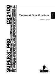
Synth programs<br />
A synth program uses three oscillators (including a noise<br />
generator) to produce wave<strong>for</strong>ms which are then processed<br />
by filters, amp, EGs, LFOs, and modulation sequencer to<br />
create sounds with a wide range of expressive character.<br />
Oscillators (OSC1, OSC2, NOISE)<br />
Filter Routing= Individual Drive/WS Position<br />
OSC1<br />
FILTER A = PreAmp<br />
OSC MOD MIXER<br />
FILTER B<br />
DRIVE/WS<br />
OSC2<br />
EG1<br />
Keyboard Track<br />
NOISE<br />
Free Assign<br />
SEQ1 SEQ2 SEQ3<br />
MOD SEQUENCER<br />
Carrier<br />
Vocoder off<br />
Modulator<br />
Oscillator 1 (OSC1) lets you choose from eight types of<br />
oscillator algorithm (ranging from basic analog synthesizer<br />
wave<strong>for</strong>ms such as sawtooth and triangle to DWGS digital<br />
synthesizer wave<strong>for</strong>ms), as well as the signals from the<br />
AUDIO INPUT, S/P DIF, and <strong>EXB</strong>-FW (separately sold<br />
option) jacks or signals from the AUX bus. You can also<br />
apply cross modulation, unison, or VPM (Variable Phase<br />
Modulation) to basic analog synthesizer wave<strong>for</strong>ms such as<br />
sawtooth or triangle wave.<br />
Oscillator 2 (OSC2) lets you choose from four different<br />
oscillator waves - sine, triangle, square, and sawtooth.<br />
Oscillator 2 can be used as the modulating oscillator <strong>for</strong> the<br />
sync modulation (SYNC) or ring modulation (RING) that<br />
are such classic analog synthesizer techniques. The best<br />
elements of SYNC and RING modulation can be combined<br />
using a third option: RING SYNC.<br />
The noise generator (NOISE) generates white noise. You can<br />
use this <strong>for</strong> a variety of sound shaping situations, such as<br />
Vocoder<br />
EG1 EG2 EG3<br />
VIRTUAL PATCH<br />
EQ<br />
To OSC1<br />
Control2 To Filter To Amp<br />
Free Assign<br />
To Mixer/Effect<br />
AMP<br />
PAN<br />
Keyboard Track<br />
Velocity<br />
JS X<br />
etc.<br />
To EQ<br />
1
2<br />
Introduction<br />
adding breath noise <strong>for</strong> a wind instrument sound, or as part<br />
of a special effect sound.<br />
Mixer (MIXER)<br />
The mixer adjusts the volume levels of oscillator 1 (OSC1),<br />
oscillator 2 (OSC2), and the noise generator (NOISE), and<br />
sends the combined signal to the filter (FILTER).<br />
Filter (FILTER A, FILTER B)<br />
The filter section consists of two multi-mode, resonant<br />
filters. The two filters can be routed in series or parallel, or<br />
even side by side in a “one oscillator per filter” arrangement.<br />
The filters adjust the tone of the sound coming from the<br />
oscillators by boosting or cutting specific frequency regions.<br />
Filter settings will have a major impact on the sound.<br />
By default, envelope generator 1 (EG1) is set to vary the<br />
cutoff frequency of the filters over time.<br />
Amp (AMP)<br />
Traditionally, the amp section controls the output volume<br />
(AMP) and the panning (PAN), or the position in the stereo<br />
field. The <strong>RADIAS</strong> program provides additional features to<br />
add more tonal complexity and “edge” to the sound -<br />
including Drive, Wave Shape control (DRIVE/WS), and<br />
Punch Level.<br />
Drive/Wave Shape does not simply apply an effect to the<br />
oscillator wave<strong>for</strong>m; it modifies the wave<strong>for</strong>m itself to<br />
create hard-edged tones. By adjusting the filter cutoff or<br />
resonance you can create even more dramatic effects.<br />
By default, envelope generator 2 (EG2) is set to vary the<br />
volume level over time.<br />
Envelope generators (EG1/EG2/EG3)<br />
Envelope generators (EG) are used to apply time-varying<br />
change to the sound parameters.<br />
You can create the desired envelope by using the four basic<br />
parameters attack time, delay time, sustain level, and release<br />
time. You can also choose linear, logarithmic, or exponential<br />
curves.<br />
EG1 is assigned to control the filter cutoff frequency, and<br />
EG2 is assigned to control the volume of the amp. You can<br />
also use virtual patching (VIRTUAL PATCH) to assign these<br />
EGs as envelope sources <strong>for</strong> other parameters.<br />
LFO (LFO1, LFO2)<br />
LFO (Low Frequency Oscillator) is used to apply cyclic<br />
change to the sound parameters.<br />
<strong>RADIAS</strong> program contains two LFOs, and <strong>for</strong> each LFO you<br />
can choose one of four wave<strong>for</strong>ms. Shape control, key sync<br />
and phase controls extend well beyond traditional LFO<br />
offerings.<br />
LFO1 is assigned to the oscillator 1 wave<strong>for</strong>m (depending<br />
on the selected wave<strong>for</strong>m), and LFO2 is assigned as a pitch<br />
modulation source controlled by the joystick +Y axis.<br />
You can also make virtual patch settings (VIRTUAL PATCH)<br />
to assign the LFOs as modulation sources <strong>for</strong> other<br />
parameters.<br />
Virtual Patch (VIRTUAL PATCH)<br />
The virtual patch section lets you freely assign modulation<br />
sources to modulate-able parameters, giving you even more<br />
flexibility <strong>for</strong> creating sounds. You can make eight virtual<br />
patch assignments in each <strong>RADIAS</strong> program.<br />
Modulation Sequencer (MOD SEQUENCER)<br />
Using a modulation sequencer, you can apply up to sixteen<br />
discrete values (steps) to a modulate-able parameter over<br />
time, in a manner similar to vintage analog synthesizers.<br />
The modulation sequence can play once, repeat, loop front<br />
to back, etc. - providing movement and complexity to the<br />
sound. The value can change abruptly at each step, or it can<br />
smoothly transition from value to value. Each <strong>RADIAS</strong><br />
program provides three sequencers, allowing you to create<br />
extremely complex tonal changes.<br />
Equalizer (EQ)<br />
You can use a three-band equalizer with sweepable midrange.<br />
Mixer, Effects<br />
The signal that has passed through the EQ can be processed<br />
by effects via a highly flexible mixer. As with EDS programs,<br />
you can use five insert effects (IFX), two master effects<br />
(MFX), and one total effect (TFX).<br />
KARMA, Drum Track, X-Y Mode, Controllers<br />
You can use this functionality in the same way as you can<br />
with EDS programs.
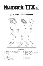
Vocoder program<br />
A vocoder applies the spectral character of the “modulator”<br />
(e.g., a signal received from the AUDIO INPUT 2 jack) to the<br />
“carrier” (e.g., a signal received from the AUDIO INPUT 1<br />
jack).<br />
The most popular way to use this is to input your voice from<br />
a mic connected to the AUDIO INPUT 2 jack, creating the<br />
impression that an instrumental sound is “talking.”<br />
Vocoder program<br />
Input Source<br />
Analog Input 1/2<br />
S/P DIF L/R<br />
FireWire L/R (option)<br />
AUX Bus<br />
AUX 1/2<br />
AUX 3/4<br />
Vocoder<br />
Audio Source<br />
AUX Bus<br />
In Source1 (Synth)<br />
In Source2<br />
LEVEL<br />
LEVEL<br />
Vocoder section (VOCODER)<br />
Audio In 1<br />
Audio In 2<br />
Synth<br />
Formant Motion Data<br />
Modulator<br />
Carrier<br />
Band1<br />
Carrier<br />
Band16<br />
Analysis<br />
Filter<br />
Resonance<br />
Synthesis<br />
Filter<br />
Frequency Offset<br />
Formant Shift<br />
The vocoder divides the audio spectrum into “bands”. In the<br />
<strong>RADIAS</strong> program, the vocoder uses 16 bands. There are<br />
actually two sets of 16 bands; the first is used to analyze the<br />
tonal characteristics of one sound (the Modulator), and the<br />
second set is used to apply the same characteristics to<br />
another sound (the Carrier). Each analysis band contains a<br />
bandpass filter and an envelope follower. Each synthesis<br />
band contains a band pass filter whose output is controlled<br />
by the matching envelope follower in the analysis band.<br />
The modulator’s audio signal is sent through the sixteen<br />
bandpass filters (the analysis filters), and the envelope<br />
follower detects the volume envelope (change over time) <strong>for</strong><br />
each of these frequency bands.<br />
The carrier’s audio signal is sent through the other set of<br />
sixteen bandpass filters (the synthesis filters), and the<br />
envelope detected from each analysis filter is applied to each<br />
synthesis filter to modulate the sound, producing the<br />
impression that the carrier sound is “talking” (the typical<br />
vocoder effect).<br />
You can use the Formant Shift and Frequency Offset<br />
parameters to shift the frequencies of the carrier bandpass<br />
filters. This will raise or lower the frequency response while<br />
preserving the character of the modulator, creating major<br />
changes in the sound.<br />
Vocoder on<br />
Modulator<br />
Vocoder<br />
Env. Follower sens<br />
Envelope<br />
Follower<br />
Band Level<br />
Modulator<br />
Select<br />
Pan<br />
EQ<br />
Carrier (CARRIER)<br />
Modulator<br />
Direct Mix<br />
Modulator<br />
High Mix<br />
To Mixer/Effect<br />
Formant<br />
Motion data<br />
Program structure<br />
A sawtooth wave (SAW) or other wave<strong>for</strong>m rich in<br />
overtones is the best choice <strong>for</strong> the carrier. As the carrier, you<br />
can use a combination of two sources (In Source1 and In<br />
Source 2).<br />
As the In Source1 you can use the mono-mixed signal from<br />
the output of the amp section (the signal be<strong>for</strong>e it is sent to<br />
the insert effects). In Program mode, the synth sound of the<br />
program is fixed as In Source 1.<br />
As the In Source 2 you can use an external input (e.g.,<br />
AUDIO INPUT 1 jack) or the AUX bus (insert effect output).<br />
Modulator (MODULATOR)<br />
Most commonly, you will input your voice as the modulator,<br />
but interesting results can also be obtained by inputting a<br />
rhythm sound as the modulator wave<strong>for</strong>m. You can use<br />
either an external input (AUDIO INPUT 2 jack) or AUX bus<br />
(an external input processed by an insert effect, or a<br />
program sound such as rhythm) as the modulator.<br />
There is also a Formant Motion function that lets you record<br />
Formant Motion Data to capture the moving characteristics<br />
of a voice or other sound, and use this data to drive the<br />
vocoder.<br />
HPF<br />
To EQ<br />
3
4<br />
Introduction<br />
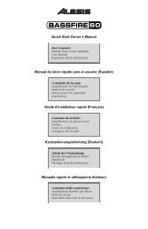
Combination structure<br />
You can combine <strong>RADIAS</strong> programs and EDS programs to<br />
create more complex sounds.<br />
<strong>RADIAS</strong> programs can be used in four timbres<br />
simultaneously.<br />
The structure of a combination and the functionality in<br />
Combination mode is the same as <strong>for</strong> combinations that use<br />
EDS programs.<br />
Combination/Song<br />
Audio Inputs<br />
Analog Input 1/2<br />
S/P DIF L/R<br />
FireWire L/R (option)<br />
AUX Bus<br />
AUX 1/2<br />
AUX 3/4<br />
Timbre/Track 01<br />
Timbre/Track 02<br />
Timbre/Track 03<br />
Timbre/Track 04<br />
OSC<br />
Audio Input<br />
Source<br />
Program (Synth)<br />
Program (Synth)<br />
Program (Synth)<br />
Program (Synth)<br />
Song structure<br />
(Sequencer mode)<br />
You can use <strong>RADIAS</strong> programs in the MIDI tracks of a song.<br />
<strong>RADIAS</strong> programs can be used in up to four MIDI tracks<br />
simultaneously.<br />
The structure of a song and the functionality in Sequencer<br />
mode is the same as <strong>for</strong> songs that use EDS programs.<br />
About the vocoder function in combinations and<br />
songs<br />
You can use the vocoder in each combination or song.<br />
Only one instance of the vocoder variation can be used in<br />
each combination or song.<br />
If you want to use a vocoder program in a combination or<br />
song, you’ll need to use the menu command Copy from<br />
program or Copy Vocoder to copy the vocoder settings of<br />
the program. You can use this <strong>for</strong> the timbre or song of one<br />
<strong>RADIAS</strong> program.<br />
Even if you’ve assigned four timbres or MIDI<br />
tracks to play programs in which the <strong>RADIAS</strong><br />
vocoder is turned on, it is not the case that four<br />
vocoders are operating.<br />
Note: Timbres or MIDI tracks using multiple <strong>RADIAS</strong><br />
programs, or timbres or MIDI tracks using EDS programs,<br />
can be used via the AUX bus as the carrier and modulator of<br />
the vocoder.<br />
Vocoder = ON<br />
Carrier Input Source1 = T02<br />
Vocoder<br />
Vocoder<br />
Carrier/Modulator<br />
Source<br />
EQ<br />
EQ<br />
EQ<br />
EQ<br />
To Mixer/Effect<br />
To Mixer/Effect<br />
To Mixer/Effect<br />
To Mixer/Effect
Quick Start<br />
Selecting and playing programs<br />
For details on connecting external devices and setting up,<br />
refer to “<strong>M3</strong> operation guide.”<br />
Synth programs<br />
Here’s how to select synth programs and try out various<br />
sounds.<br />
Selecting and playing<br />
1. Press the PROG switch to enter Program mode.<br />
2. Press the BANK SELECT I-F switch to select programs<br />
from bank INT-F.<br />
3. Use the q and u switches, the VALUE dial, or the<br />
numeric switches to select a program.<br />
4. Play the keyboard or pads to hear the sound of the<br />
program.<br />
There are also other ways to select programs, such as by<br />
category. For more about other ways to select programs,<br />
please see “Selecting Programs” on page 37 of the <strong>M3</strong><br />
operation guide.<br />
Using controllers to vary the sound<br />
1. Numerous controllers are located in the left side of the<br />
<strong>M3</strong>’s front panel. While you play the keyboard, operate<br />
the joystick, ribbon controller, and SW1 and SW2<br />
switches to vary the sound.<br />
The result will differ <strong>for</strong> each program, so try them all out to<br />
see what each controller does <strong>for</strong> the particular program<br />
you’ve selected.<br />
For details on these controllers, please see “Using<br />
Controllers” on page 41 of the <strong>M3</strong> operation guide.<br />
2. Use the Realtime Controller function of the control<br />
surface to control the sound parameters. Press the<br />
CONTROL ASSIGN REALTIME CONTROLLER<br />
switch (the LED will light).<br />
You can control the sound parameters that are assigned to<br />
the sliders and switches.<br />
For details on Realtime Controller, please see “Using<br />
realtime control to edit sounds or effects” on page 48 of the<br />
<strong>M3</strong> operation guide.<br />
3. Use the Tone Adjust function of the control surface to<br />
control the sound programs of the <strong>RADIAS</strong> program.<br />
Press the CONTROL ASSIGN TONE ADJUST switch<br />
(the LED will light).<br />
You can control the sound parameters that are assigned to<br />
the sliders and switches.<br />
For details on the default Tone Adjust settings <strong>for</strong> a <strong>RADIAS</strong><br />
program, please see “Tone Adjust Default Settings” on<br />
page 24.<br />
Note: You can use the switches and sliders to control the<br />
parameters assigned to Realtime Controller and Tone Adjust<br />
even when you’re in the main page of the screen. However<br />
since it’s most convenient to be able to see the values change<br />
in the display while you adjust them, you’ll probably want<br />
to be viewing the PROG P08: Control Surface page. Press the<br />
Control Surface tab located in the lower right of the display.<br />
When you operate the eight switches and sliders, they will<br />
per<strong>for</strong>m the functions assigned to them, and the sound will<br />
change. The objects in the display will also change<br />
accordingly.<br />
5
6<br />
Quick Start<br />
Vocoder programs<br />
Let’s select a vocoder program and try out the vocoder<br />
function.<br />
You’ll need to connect a mic to the AUDIO INPUT 2 jack.<br />
Be<strong>for</strong>e you connect the mic, set the AUDIO INPUT LEVEL<br />
knob to MIN.<br />
Selecting and playing<br />
1. Connect your mic to the rear panel AUDIO INPUT 2<br />
jack.<br />
2. Set the MIC/LINE switch to MIC.<br />
3. Select vocoder program 127 from program bank INT-F.<br />
4. Access the PROG P0-7: Sampling/Audio In page.<br />
5. Set the following parameters.<br />
• Use Global setting: Off (unchecked)<br />
• Input: Analog<br />
• Input 2 BUS Select: L/R<br />
6. While vocalizing into your mic, use the AUDIO INPUT<br />
LEVEL knob to adjust the input level.<br />
The optimum input level is a point slightly below the level<br />
where the “ADC OVER!” (AD converter input overload)<br />
indication appears.<br />
When you’ve finished adjusting the level, turn Input 2 BUS<br />
Select Off.<br />
7. While vocalizing into your mic, play the keyboard.<br />
You’ll hear the vocoder sound.<br />
Using controllers to vary the sound<br />
For vocoder programs as well, various sound parameters<br />
are assigned to the Realtime Controller and Tone Adjust<br />
functions of the control surface. Try operating the switches<br />
and sliders, and see how they affect the sound.
Editing a program<br />
In the PROG P0: Play page, you can select and play <strong>RADIAS</strong><br />
programs, use the control surface to per<strong>for</strong>m quick editing,<br />
and adjust the KARMA settings in the same way as <strong>for</strong> EDS<br />
programs. In other pages, you can make more detailed edits<br />
to the sound.<br />
Basic settings <strong>for</strong> the program<br />
To edit a <strong>RADIAS</strong> program, you’ll start in the PROG P1-1:<br />
Program Basic page, where you can specify settings such as<br />
scale type and audio input source.<br />
Here we’ll explain how to make a <strong>RADIAS</strong> program play<br />
monophonically.<br />
Voice Assign Mode<br />
1. Set the “Voice Assign Mode” to Mono.<br />
Voice Assign Mode specifies how the oscillators will<br />
produce sound.<br />
With the Mono setting, only one note will be heard even if<br />
you play a chord on the keyboard. This setting is suitable if<br />
you’re per<strong>for</strong>ming a synth bass, synth lead, or other solo<br />
instrument sound.<br />
2. Set “Trigger Mode” to Multi.<br />
Trigger Mode specifies how the sound will be triggered.<br />
With the Multi setting, the sound is retriggered each time<br />
you play a note.<br />
3. Set “Priority” to Last.<br />
With the Last setting, priority will be given to sounding the<br />
last-played note if you’ve held down two or more keys<br />
simultaneously.<br />
4. Set “Unison” On (checked).<br />
Unison selects whether multiple voices will be sounded in<br />
unison when you play a single note.<br />
Note: If you want to produce a richer sound, turn Unison on<br />
so that multiple voices will be “stacked.” The Number of<br />
Voices specifies the number of voices that will be stacked.<br />
Operation<br />
5. Use “Number of Voices” to specify the number of<br />
voices that you want to sound simultaneously.<br />
6. Use “Detune [cents]” to specify the amount of detuning<br />
(pitch difference) between the voices that are sounded<br />
simultaneously.<br />
The number of simultaneously-sounded voices specified by<br />
Number of Voices will be equally spread apart in pitch by<br />
the specified Detune [cents] amount.<br />
7. Use “Spread” to specify the stereo position of the<br />
simultaneously-sounded voices.<br />
The simultaneously-sounded voices specified by Number of<br />
Voices will be evenly spread across the stereo field<br />
according to the Spread setting.<br />
Oscillators<br />
<strong>RADIAS</strong> programs consist of three oscillators: oscillator 1,<br />
oscillator 2, and a noise generator.<br />
Here’s how to select the oscillator wave<strong>for</strong>m and adjust the<br />
output level.<br />
Selecting the wave<strong>for</strong>m<br />
OSC1 (Oscillator 1)<br />
1. Use the “Wave<strong>for</strong>m” to select the wave<strong>for</strong>m <strong>for</strong><br />
oscillator 1.<br />
You can choose one of nine different wave<strong>for</strong>ms, including<br />
an external audio input (Audio In).<br />
2. Use the “OSC Mod” to select the type of modulation<br />
being applied to oscillator 1.<br />
You can choose one of four modulation types.<br />
If you’ve selected Formant, Noise, DWGS, or<br />
AudioIn as the wave<strong>for</strong>m, the only available<br />
modulation type will be Wave<strong>for</strong>m (Wave<strong>for</strong>m<br />
modulation).<br />
3. Use the “Control 1” and “Control 2” to specify the<br />
wave<strong>for</strong>m parameters.<br />
The parameters that are controlled by the Control 1 and<br />
Control 2 will depend on the wave<strong>for</strong>m and the modulation<br />
type you’ve selected.<br />
For details on the oscillator parameters, please see “2–1a:<br />
OSC1” on page 30.<br />
7
8<br />
Operation<br />
OSC2 (Oscillator 2)<br />
1. Use the “Wave<strong>for</strong>m” to select the wave<strong>for</strong>m of<br />
oscillator 2.<br />
You can choose one of four different wave<strong>for</strong>ms. The most<br />
common way to use this is to select the same wave<strong>for</strong>m as<br />
oscillator 1, and change its pitch slightly to create a rich<br />
sound.<br />
2. Use the “OSC Mod” to select the modulation type <strong>for</strong><br />
oscillator 2.<br />
You can choose one of three modulation types.<br />
3. Use the “Semitone” to adjust the pitch of oscillator 2 in<br />
semitone steps.<br />
Some of the more common ways to set this parameter is to<br />
lower the pitch by one octave (–12) or two octaves (–24)<br />
relative to the pitch of oscillator 1. Vintage analog<br />
synthesizer players would sometimes set the oscillators a<br />
fourth (+5) or fifth (+7) apart in pitch.<br />
4. Use the “Tune” to adjust the pitch of oscillator 2.<br />
You can produce a richer sound by slightly changing the<br />
pitch to create a detuned effect.<br />
Mixer<br />
The mixer lets you adjust the output level of each oscillator.<br />
This setting will determine the input level to the filters.<br />
1. Use the “OSC1 Level” to adjust the volume of oscillator<br />
1.<br />
2. Use the “OSC2 Level” to adjust the volume of oscillator<br />
2.<br />
3. Use the “Noise Level”to adjust the volume of the noise<br />
generator.<br />
You can use the noise generator to simulate the breath noise<br />
of a wind or brass instrument, or to create sound effects.<br />
The oscillator wave<strong>for</strong>m you select here can be processed by<br />
the filters, drive/waveshaping, EG, and LFO etc. to create<br />
the sound you want.<br />
Filter<br />
The filters allows you to diminish or emphasize specified<br />
frequency areas of the sound. The tone of the sound will<br />
depend significantly on the filter settings.<br />
<strong>RADIAS</strong> programs provide the three basic filter types low<br />
pass filter, high pass filter, and band pass filter, as well as<br />
intermediate types that interpolate between the characters<br />
of adjacent filters.<br />
The basic filter settings, including the filter routing, filter<br />
type, cutoff frequency, and resonance, are set on the PROG<br />
P3: Filter page.<br />
Filter Routing<br />
1. Use “Filter Routing” to select the filter routing.<br />
<strong>RADIAS</strong> programs provide two filters (filter A and filter B).<br />
You can choose to use one or both filters, and how the two<br />
will be connected if both are used.<br />
For more in<strong>for</strong>mation, please see “Filter Routing” on<br />
page 34.<br />
Filter A, Filter B (Filter settings)<br />
1. Use the “Type/Balance” select the type of filter.<br />
You can adjust the knob to obtain intermediate characters<br />
between these filter types. The filter type will have a major<br />
effect on the character of the sound.<br />
If Filter Routing is Serial, Parallel, or Individual, you can<br />
adjust this independently <strong>for</strong> filters A and B.<br />
For more in<strong>for</strong>mation, please see “3–1: Filter” on page 34.<br />
2. Use the “Frequency” to adjust the cutoff frequency of<br />
filter.<br />
Higher settings will make the sound brighter. The result will<br />
depend on the filter type.<br />
For more in<strong>for</strong>mation, please see “Frequency (Cutoff<br />
Frequency)” on page 35.<br />
3. Use the “Resonance” to adjust the resonance of filter 1.<br />
Higher settings will increasingly emphasize the region<br />
around the cutoff frequency, producing a nasal tone or a<br />
whistle.<br />
4. Use the “EG1 Intensity” to adjust the depth of the effect<br />
that EG1 will have on the cutoff frequency of filter.<br />
You can adjust this independently <strong>for</strong> filters A and B.<br />
If you turn the knob toward the right of the center position<br />
(“+” values), the EG will move the filter in the positive<br />
direction (i.e., if the filter type is LPF, the sound will become<br />
brighter).<br />
If you turn the knob toward the left of the center position (“–<br />
” values), the EG will move the filter in the negative
direction (i.e., if the filter type is LPF, the sound will become<br />
darker).<br />
Note: EG1 envelope settings are made in the PROG P5: EG/<br />
LFO/SEQ page. (☞p.38“5–1: EG1 (Filter), 5–2: EG2 (Amp),<br />
5–3: EG3”)<br />
5. Use “Keyboard Track” to specify how keyboard<br />
tracking (the keyboard position on which you play)<br />
will affect the cutoff frequency.<br />
For more in<strong>for</strong>mation, please see “Keyboard Track” on<br />
page 35.<br />
6. Use “Velocity Sens” to specify how velocity (the <strong>for</strong>ce<br />
with which you play the keys) will affect the cutoff<br />
frequency.<br />
For more in<strong>for</strong>mation, please see “Velocity Sens (Velocity<br />
Sensitivity)” on page 35.<br />
Amp<br />
Editing a program Amp<br />
Amp is where you specify drive and wave shape, adjust the<br />
volume, and set the pan.<br />
These settings are made in the PROG P4-1: Amp/<br />
WaveShape/Driver page.<br />
Drive/Wave Shape<br />
Drive/Wave Shape modifies the wave<strong>for</strong>m itself – it is not<br />
an effect that is applied to the oscillator wave<strong>for</strong>m. Here’s<br />
how to select the wave shape.<br />
1. Set “Drive/Wave Shape” to Wave Shape.<br />
2. Use “Wave Shape Type” to select the type of wave<br />
shaping.<br />
This choice is available if Drive/Wave Shape is set to Wave<br />
Shape. You can choose from a wide variety of wave shape<br />
types.<br />
For more in<strong>for</strong>mation, please see “Wave Shape Type” on<br />
page 36.<br />
3. Use “Position” to select the position at which wave<br />
shaping will be applied.<br />
You can apply drive and wave shaping be<strong>for</strong>e filter A or<br />
be<strong>for</strong>e the amp section.<br />
For more in<strong>for</strong>mation, please see “Position” on page 36.<br />
4. Use “Depth” to specify the depth of drive or wave<br />
shaping.<br />
Amp Level<br />
1. Use “Amp Level” to specify the basic volume level. The<br />
volume level you specify here will be changed by EG2<br />
and other modulation sources.<br />
2. Use “Punch Level” to adjust the mixing amount of the<br />
pulse wave<strong>for</strong>m added to the oscillator output.<br />
Higher settings will emphasize the attack.<br />
3. Use “Keyboard Track” to specify how keyboard<br />
tracking will affect the volume.<br />
This lets you make the volume change as you play higher or<br />
lower on the keyboard.<br />
Pan<br />
1. Use “Pan” to specify the stereo position.<br />
Note: You can produce an auto pan effect by using a virtual<br />
patch to modulate this with an LFO.<br />
For more in<strong>for</strong>mation, please see “Virtual Patch” on page 11.<br />
9
10<br />
Operation<br />
EG (Envelope Generator)<br />
An EG (envelope generator) applies time-varying change to<br />
a parameter of the sound.<br />
EG1 is assigned as the envelope source <strong>for</strong> filter cutoff<br />
frequency, and EG2 is assigned as the envelope source <strong>for</strong><br />
the amp volume.<br />
You can also use a virtual patch to assign an EG as an<br />
envelope source <strong>for</strong> another parameter.<br />
For more in<strong>for</strong>mation, please see “Virtual Patch” on page 11.<br />
Amp Level<br />
Level<br />
0<br />
The five parameters (attack time, decay time, release time,<br />
sustain level, and curve) that make up each envelope can be<br />
edited in the PROG 5-1: EG1, P5-2: EG2, and P5-3: EG3<br />
pages.<br />
Envelope settings<br />
Sustain Level<br />
Note on Note off<br />
Attack Time<br />
Decay Time Release Time<br />
1. Edit the “Attack Time”, “Decay Time”, “Release Time”,<br />
and “Sustain Level”.<br />
Higher values <strong>for</strong> Attack Time, Decay Time, and Release<br />
Time will lengthen the time over which the tone or volume<br />
will change.<br />
2. Use “Curve” to select the curve by which the decay and<br />
release time will change.<br />
You can choose linear, logarithmic, or exponential curve.<br />
This will affect the way in which the envelope changes.<br />
EG Level/Time Modulation<br />
Time<br />
You can use velocity and keyboard tracking to modulate the<br />
EG.<br />
1. Use “Level Velocity” Intensity to specify how velocity<br />
will affect the amount of amplitude change produced<br />
by the EG.<br />
Higher values will allow variations in your playing velocity<br />
to produce greater change in the amplitude.<br />
2. Use “Decay/Release Time Keyboard Track” to specify<br />
how keyboard tracking will affect the decay time and<br />
release time.<br />
Higher values allow keyboard tracking to affect the EG time<br />
settings more greatly.<br />
3. Use “Decay/Release Time Velocity Intensity” to specify<br />
how velocity will affect decay time and release time.<br />
Higher values will allow velocity to affect the EG time<br />
settings more greatly.
LFO<br />
These are the parameters <strong>for</strong> the LFOs (Low Frequency<br />
Oscillators). An LFO can apply cyclic change to the sound.<br />
LFO1 is internally connected as the modulation source <strong>for</strong><br />
oscillator 1 wave<strong>for</strong>m.<br />
LFO2 is internally connected as the modulation source <strong>for</strong><br />
the oscillator pitch modulation controlled by the joy-stick.<br />
You can also use a virtual patch to assign an LFO as a<br />
modulation source <strong>for</strong> other parameters. For more<br />
in<strong>for</strong>mation, please see “Virtual Patch” on page 11.<br />
Wave<strong>for</strong>m, speed (frequency), and tempo synchronization<br />
can be edited in the PROG P5-4: LFO1 or P5-5: LFO2 pages.<br />
LFO wave<strong>for</strong>m<br />
1. Use “Wave<strong>for</strong>m” to select the basic wave<strong>for</strong>m of the<br />
LFO.<br />
The change produced by the LFO depends on the<br />
wave<strong>for</strong>m. Select various wave<strong>for</strong>ms and notice the<br />
difference in how they affect the sound.<br />
2. Use “Phase” to specify the starting position of the<br />
wave<strong>for</strong>m.<br />
Notice that this setting moves the wave<strong>for</strong>m to left or right.<br />
You can create interesting effects by offsetting the phase of<br />
one LFO relative to the other LFO.<br />
This parameter is available when Key Sync is 1st Note or<br />
Each Note.<br />
3. Use “Shape” to modify the basic wave<strong>for</strong>m of the LFO.<br />
The change produced by this parameter will depend on the<br />
Wave<strong>for</strong>m you’ve selected.<br />
4. Use “Frequency [Hz]” to specify the frequency of the<br />
<strong>for</strong>mant motion.<br />
This parameter is valid if MIDI/Tempo Sync. is Off<br />
(unchecked).<br />
MIDI/Tempo Sync<br />
1. Use “MIDI/Tempo Sync.” to specify how the LFO will<br />
synchronize.<br />
If this is On (checked), the LFO will synchronize to the<br />
system tempo specified by the TEMPO knob or TAP<br />
TEMPO switch, or to the MIDI Clock from an external<br />
device.<br />
2. Use “Base Note” to specify the LFO cycle.<br />
This specifies the ratio of the LFO cycle relative to the<br />
system tempo or external MIDI clock. This parameter is<br />
valid if MIDI/Tempo Sync. is On (checked).<br />
Virtual Patch<br />
Editing a program LFO<br />
These are the parameters <strong>for</strong> the Virtual Patch function.<br />
Virtual Patch is a function that lets you assign modulation<br />
sources such as EG or LFO to a variety of parameters. For<br />
each timbre you can create up to eight of these<br />
combinations.<br />
Make these settings in the PROG P1-2: Virtual Patch page.<br />
Virtual Patch settings<br />
1. Use “Src (Source)” to select a modulation source.<br />
You can select EG, LFO, or various controllers as a<br />
modulation source.<br />
For more in<strong>for</strong>mation, please see “Src (Source)” on page 28.<br />
2. Use “Dst (Destination)” to select the parameter that<br />
will be modulated.<br />
For more in<strong>for</strong>mation, please see “Dst (Destination)” on<br />
page 28.<br />
3. Use “Int (Intensity)” to specify the depth of<br />
modulation.<br />
Controlling volume<br />
If you set Src (Source) to LFO2, Dst (Destination) to Amp<br />
Level, and adjust Int (Intensity) as desired, LFO2 will<br />
produce a tremolo effect.<br />
Controlling pan<br />
If you set Src (Source) to LFO2, Dst (Destination) to Pan,<br />
and adjust Int (Intensity) as desired, LFO2 will move the<br />
sound between left and right to produce an auto pan effect.<br />
Controlling filter<br />
If you set Src (Source) to LFO2, Dst (Destination) to Filter<br />
A Frequency, and adjust Int (Intensity) as desired, LFO2<br />
will vary the filter cutoff frequency to produce an auto wah<br />
effect.<br />
You can use an LFO to modulate a wide range of parameters<br />
in addition to those listed above.<br />
Source and Destination settings, and their effect<br />
Src (Source) Dst (Destination) Modulation effect<br />
LFO2 Amp Level Tremolo effect<br />
LFG2 Pan Auto pan effect<br />
LFO2 Filter A Frequency Auto wah effect<br />
11
12<br />
Operation<br />
Modulation Sequencers<br />
The Modulation Sequencers let you apply time-varying<br />
change to sound parameters in a way similar to analog<br />
sequencers of the past. A modulation sequencer stores a<br />
discreet value <strong>for</strong> each of sixteen individual steps, and<br />
consecutively applies these values to vary the sound over<br />
time. Since three modulation sequencers are provided <strong>for</strong><br />
each program, you can create sounds that change in very<br />
complex ways.<br />
Make these settings in the PROG P5-6: MOD SEQ1, P5-7:<br />
MOD SEQ2, and P5-8: MOD SEQ3 pages.<br />
Here we’ll explain how to use modulation sequencer 1 to<br />
modulate the oscillator pitch.<br />
SEQ Common<br />
Be<strong>for</strong>e we specify each step of the actual sequence data<br />
itself, we’ll need to specify the number of steps in the<br />
sequence, and the playback method. These parameters are<br />
common to all three modulation sequencers.<br />
1. Access the PROG P5-6: MOD SEQ1 page.<br />
2. Turn on “MOD SEQ” On (checked).<br />
If this is On (checked), the three modulation sequencers will<br />
be on, and the values stored in each step of each modulation<br />
sequencer will modulate the sound parameters.<br />
3. Set “LastStep” to 16.<br />
The sequence will begin playing when a note-on occurs, and<br />
will proceed <strong>for</strong> sixteen steps.<br />
4. Set “Sequence Type” to Alt1.<br />
☞ “Sequence Type” on page 40<br />
5. Set “Run Mode” to Loop.<br />
☞ “Run Mode” on page 41<br />
6. Set “KeySync” to 1st Note.<br />
☞ “Key Sync.” on page 41<br />
7. Set “Resolution” to .<br />
The sequencer will advance one step <strong>for</strong> each note value you<br />
specify here, relative to the tempo. If this is set to , the<br />
sequencer will advance one step <strong>for</strong> each quarter-note beat.<br />
Editing the steps<br />
1. Set “Destination Param” to Pitch.<br />
2. Use “Motion” to specify how the values stored in each<br />
step will change when the modulation sequencer plays.<br />
For this example, choose Smooth.<br />
3. While playing the keyboard so that you can hear the<br />
sound, specify the sequence data <strong>for</strong> each step. If you<br />
want to adjust the value in detail, use the VALUE dial<br />
etc.<br />
The value of each step is applied as an amount of relative<br />
change to the parameter’s assigned value.
Editing a vocoder program<br />
Here’s how to make settings <strong>for</strong> the vocoder’s carrier,<br />
modulator, and output.<br />
These settings are made in the PROG P6-1: Carrier/<br />
Modulator page.<br />
Vocoder on/off<br />
1. Use “Vocoder” to turn the vocoder on/off. If this is on<br />
(checked), the vocoder will be on.<br />
Carrier Input<br />
As the vocoder’s carrier, you can use two audio signals: the<br />
mono-mixed signal output from the amp section (the signal<br />
be<strong>for</strong>e entering the EQ) and the audio signal from an<br />
external input or the AUX bus.<br />
1. Use “In Source 1 Level” to specify the volume of the<br />
oscillator input to the carrier.<br />
Input source 1 is the mono-mixed signal from the amp<br />
section output (the signal be<strong>for</strong>e entering the EQ).<br />
2. Use “In Source 2 Select” to select input source 2 to the<br />
carrier.<br />
3. Use “In Source 2 Level” to specify the volume of input<br />
source 2 to the carrier.<br />
Modulator, Out Mix (modulator and<br />
vocoder output settings)<br />
As the modulator of the vocoder, you can use the external<br />
input from the AUDIO INPUT 2 jack, the R-channel of the<br />
S/P DIF or FireWire (if the <strong>EXB</strong>-FW option is installed), the<br />
audio signal from the AUX bus, or <strong>for</strong>mant motion data.<br />
In this example, we’ll explain how to use a mic connected to<br />
the AUDIO INPUT 2 jack as the modulator.<br />
1. Set “Modulator” to Audio.<br />
2. Set “Source” to Audio In2.<br />
The mic or other device connected to the AUDIO INPUT 2<br />
jack will be the modulator.<br />
Note: If you’re using a signal from the AUDIO INPUT jack as<br />
an input source, make sure that the PROG P1: Program Basic<br />
page Audio In (OSC&Vocoder) Source Audio Inputs (Send<br />
to <strong>RADIAS</strong>) parameter is set to Analog Input 1/2.<br />
3. Use “Vocoder Output Level” to specify the volume of<br />
the vocoder output.<br />
4. Use “Modulator Direct Mix” to adjust the level of the<br />
modulator input source that is mixed into the vocoder<br />
output.<br />
Editing a program Editing a vocoder program<br />
5. Use “GateSens” to adjust the gate sensitivity. Adjust<br />
this so that the vocoder sound output is not interrupted<br />
in an unnatural way.<br />
6. Use “Threshold” to cut the noise when there is no<br />
input. Raising this setting will make it easier <strong>for</strong> the<br />
sound to be cut. Adjust this so that noise is not<br />
obtrusive when you’re not speaking into the mic.<br />
7. Use “Modulator HPF Gate” and “Modulator High Mix”<br />
to adjust the high-frequency portion of the input<br />
source that will be mixed into the vocoder output.<br />
Use Modulator HPF Gate to specify whether the highfrequency<br />
portion of the input source mixed into the<br />
vocoder output will be heard only while the internal sound<br />
generator is heard, or whether it will always be heard as<br />
long as there is an input from Source.<br />
Use Modulator High Mix to specify the amount of the highfrequency<br />
portion of the input source that will be mixed into<br />
the vocoder output. Raising this setting will emphasize the<br />
consonants of your voice.<br />
Filter settings<br />
Here you’ll make settings <strong>for</strong> the modulator’s envelope<br />
follower and the carrier’s band-pass filters (synthesis<br />
filters). These settings are made in the PROG P6-2: Vocoder<br />
page.<br />
Filter (synthesis filter and envelope follower settings)<br />
1. Use “Formant Shift” to change the shift amount <strong>for</strong> the<br />
band-pass filters. By shifting the filters you can produce<br />
dramatic changes in the character of the vocoder<br />
output.<br />
2. Use “Frequency Offset” to adjust the offset to the cutoff<br />
frequency of the band-pass filters.<br />
You can adjust the filter shift amount in a range of +/-2<br />
steps. In conjunction with Formant Shift, this lets you shift<br />
the cutoff frequency in a range of +/-4 steps. (☞p.44)<br />
3. Use “Resonance” to specify the amount of resonance<br />
<strong>for</strong> the band-pass filters.<br />
4. Use “Mod Source” to select the modulation source that<br />
will be applied to the cutoff frequency offset<br />
(“Frequency Offset”), and use “Mod Intensity” to<br />
specify the depth of modulation.<br />
5. Use “Env. Follower Sens” to adjust the sensitivity of the<br />
envelope follower.<br />
Higher settings will produce a smoother rise in the vocoder<br />
output and a longer release sound.<br />
Band 1-16: Pan and Level (output level and pan<br />
setting <strong>for</strong> each band of the synthesis filter)<br />
1. Use “Level” to adjust the output level of each filter.<br />
2. Use “Pan” to adjust the pan of each filter.<br />
13
14<br />
Operation<br />
Formant Motion function<br />
The <strong>for</strong>mant motion function lets you use data such as a<br />
previously-recorded voice as the input to the modulator,<br />
causing the vocoder to produce sound. This lets you play<br />
the vocoder without having to vocalize into the mic.<br />
The <strong>EXB</strong>-<strong>RADIAS</strong> contains preloaded data <strong>for</strong> sixteen<br />
<strong>for</strong>mant motions.<br />
Assigning a <strong>for</strong>mant motion to the modulator<br />
Here’s how to play the vocoder by using the factory-set<br />
<strong>for</strong>mant motion data.<br />
1. In Program mode, select a vocoder program.<br />
☞ “Vocoder program” on page 3<br />
2. Access the PROG P1: Carrier/Modulator page.<br />
3. Set “Modulator” to Formant Motion.<br />
4. Use “Select” to select the desired <strong>for</strong>mant motion data.<br />
You can select from sixteen choices: Formant Motion 00–15.<br />
5. Use “Play Mode” to specify how the <strong>for</strong>mant motion<br />
data will play back.<br />
If you select Trigger Reset, the <strong>for</strong>mant motion data will<br />
reset to its beginning each time you play a note.<br />
6. Play the keyboard.<br />
The vocoder will sound using the <strong>for</strong>mant motion data.<br />
Recording your own <strong>for</strong>mant motion data<br />
Here’s how you can connect a mic to the rear panel AUDIO<br />
INPUT 2 jack and record your own <strong>for</strong>mant motion data.<br />
1. Connect a mic to the rear panel AUDIO INPUT 2 jack,<br />
and use “Program Select” to select a vocoder program.<br />
☞ “Vocoder program” on page 3<br />
2. Adjust the mic input level.<br />
☞ “Vocoder program” on page 3<br />
3. Access the PROG P6-1: Carrier/Modulator page.<br />
4. Turn “Formant Motion REC” On, and speak into the<br />
mic.<br />
Recording will begin when you turn Formant Motion REC<br />
On.<br />
5. Turn “Formant Motion REC” Off to stop recording.<br />
Recording will stop automatically if the memory<br />
capacity assigned to the data becomes full<br />
(approximately 7.5 seconds).<br />
6. Set “Modulator” to Formant Motion.<br />
7. Play the keyboard.<br />
The vocoder will sound using the <strong>for</strong>mant motion data you<br />
recorded.<br />
If you want to keep the data you recorded, you’ll need to<br />
write the <strong>for</strong>mant motion data. For more in<strong>for</strong>mation, please<br />
see “Write Formant Motion Data” on page 46.<br />
Writing <strong>for</strong>mant motion data<br />
Here’s how the <strong>for</strong>mant motion data you recorded can be<br />
written into internal memory. The internal memory can hold<br />
sixteen sets of <strong>for</strong>mant motion data.<br />
We recommend that you write the <strong>for</strong>mant motion<br />
data immediately after you’ve recorded it. The<br />
data will be lost if you per<strong>for</strong>m any of the<br />
following operations be<strong>for</strong>e writing.<br />
• Selecting other <strong>for</strong>mant data<br />
• Selecting another program<br />
•Turning off the power<br />
• Receiving a MIDI dump of the corresponding<br />
data from an external connected device<br />
1. In the PROG P6: Vocoder page, choose the menu<br />
command “Write Formant Motion Data” to access the<br />
dialog box.<br />
2. The upper line shows the name of the <strong>for</strong>mant motion<br />
data.<br />
If you want to edit the name of the <strong>for</strong>mant motion data,<br />
press the text edit button to access the text edit dialog box,<br />
and enter the desired name.<br />
3. Use the “To” field to select the writing destination.<br />
4. Press the OK button to write the <strong>for</strong>mant motion data,<br />
or press the Cancel button if you decide not to write the<br />
data.<br />
Never turn off the power while the data is being<br />
written. Doing so may damage the data.<br />
Note: The data that is written will be held in internal<br />
memory even when the power is off. You can also use the<br />
Media mode menu command “Save PCG” to save it on an<br />
external memory device. The data is saved as part of the<br />
PCG file.
Creating your own program<br />
You can create original sounds by editing a preloaded<br />
program or by editing an initialized program from scratch.<br />
These programs you create can be saved (written) to bank<br />
INT-F or to a user bank that has been assigned <strong>for</strong> saving<br />
<strong>RADIAS</strong> programs.<br />
Saving a program<br />
<strong>RADIAS</strong> programs can be saved in bank INT-F and in user<br />
banks whose bank type has been set to <strong>RADIAS</strong> by the<br />
Global mode menu command “Set Program User-Bank<br />
Type.” For more in<strong>for</strong>mation, please see “Set Program User-<br />
Bank Type” on page 66.<br />
The save procedure is the same as <strong>for</strong> EDS programs. For<br />
more in<strong>for</strong>mation, please see “Saving your edits” on page 50<br />
of the <strong>M3</strong> operation guide.<br />
Editing a program Creating your own program<br />
15
16<br />
Operation<br />
Editing a combination (Combination mode)<br />
You can use <strong>RADIAS</strong> programs in the timbres of a<br />
combination, and create combinations that use them<br />
together with the programs of banks INT-A–E, INT-G, and<br />
USER-A–G. Up to four <strong>RADIAS</strong> programs can be used in<br />
one combination. The maximum polyphony of the <strong>RADIAS</strong><br />
programs will be 24 voices.<br />
Timbre settings<br />
Here we’ll explain how to select bank INT-F programs so<br />
they can be played.<br />
1. Select the combination that you want to edit.<br />
2. Access the COMBI P2-5: <strong>RADIAS</strong> T01-08 or P2-6:<br />
<strong>RADIAS</strong> T09-16 page.<br />
3. In “Program Select,” turn “Enable <strong>RADIAS</strong>” on<br />
(checked) <strong>for</strong> the timbres in which you want to use a<br />
<strong>RADIAS</strong> program. When you play the keyboard, you’ll<br />
hear the <strong>RADIAS</strong> program.<br />
Note: You can turn up to four Enable <strong>RADIAS</strong> settings on.<br />
Timbres <strong>for</strong> which this is off (unchecked) will not sound.<br />
4. Access the COMBI P0-1: Combination Select T01-08 or<br />
P0-2: Combination Select T09-16 page.<br />
An indication of “ ” is shown above the category <strong>for</strong><br />
timbres whose Enable <strong>RADIAS</strong>” On (checked).<br />
5. Use “Program Select” to select a bank INT-F program.<br />
6. Edit the parameters of each timbre, make arpeggiator<br />
settings, and make settings <strong>for</strong> routing, insert effects,<br />
master effects, and total effects.<br />
However, the following parameters will operate in a<br />
different way than when you’re using an EDS program.<br />
Refer to the parameter guide.<br />
• COMBI P3-3(4)c: Force OSC Mode, OSC Select,<br />
Portamento (☞p.54)<br />
• COMBI P3-5(6)c: Pitch Transpose, Detune (Use BPM<br />
Adjust in Menu) (☞p.54)<br />
• COMBI P3-7(8)c: Type (Combi’s Scale) (☞p.55)<br />
• The Keyboard Zones / Velocity Zones “Top Slope” and<br />
“Bottom Slope” settings will have no effect. (COMBI P4:<br />
Zone/Delay)
Editing a song (Sequencer mode)<br />
You can use <strong>RADIAS</strong> programs in MIDI tracks of a song. As<br />
<strong>for</strong> a combination, up to four <strong>RADIAS</strong> programs can be used<br />
in one song. The maximum polyphony of the <strong>RADIAS</strong><br />
programs will be 24 voices.<br />
MIDI track settings<br />
The way in which to make settings, the operation of the<br />
parameters, and the points of caution are the same as <strong>for</strong> a<br />
combination.<br />
For more in<strong>for</strong>mation, please see “Editing a combination<br />
(Combination mode)” on page 16.<br />
Editing a song (Sequencer mode) MIDI track settings<br />
17
18<br />
Operation<br />
Restoring the factory settings (Global mode)<br />
Here’s how to restore the <strong>RADIAS</strong> programs and the<br />
<strong>RADIAS</strong> <strong>for</strong>mant motion data to the state in which it was<br />
when the <strong>EXB</strong>-<strong>RADIAS</strong> was installed. You can restore the<br />
<strong>EXB</strong>-<strong>RADIAS</strong> to its initially installed state by loading the<br />
preloaded data.<br />
Never turn off the power while the data is being<br />
loaded.<br />
Be<strong>for</strong>e you load the preload data, go to the Global<br />
mode P0: Basic Setup, System Preference page,<br />
and uncheck the Memory Protect settings <strong>for</strong> the<br />
data that you want to load. If you execute this<br />
operation with these settings checked, a message<br />
of “Memory Protected” will appear, and the data<br />
will not be loaded.<br />
When you load a data, the data in the <strong>M3</strong>’s internal<br />
memory will be overwritten. If you want to keep the<br />
data that is currently in internal memory, use “Save<br />
All” or “Save PCG” to save it be<strong>for</strong>e you continue.<br />
Restoring the <strong>RADIAS</strong> program<br />
data to the factory-set state<br />
1. Access the Global mode P0: Basic Setup, Basic page.<br />
Press the GLOBAL switch to enter Global mode.<br />
If the Global P0: Basic Setup, Basic page is not shown, press<br />
the EXIT switch and then press the Basic tab.<br />
2. Press the menu button, and choose “Load Preload/<br />
Demo Data.”<br />
A dialog box will appear.<br />
3. Specify the “Kind” and bank.<br />
Set Kind: Program, and Bank: I–F To I–F (see the<br />
illustration)<br />
Note: <strong>RADIAS</strong> programs can be saved in bank INT-F and in<br />
user banks whose bank type is set to <strong>RADIAS</strong>.<br />
☞ “Set Program User-Bank Type” on page 66<br />
4. Press the OK button to execute loading. If you decide to<br />
cancel, press the Cancel button.<br />
When you press the OK button, a dialog box will ask you <strong>for</strong><br />
confirmation. Press the OK button to execute loading.<br />
Restoring the <strong>for</strong>mant motion<br />
data to the factory-set state<br />
1. Per<strong>for</strong>m steps 1 and 2 of “Restoring <strong>RADIAS</strong> programs<br />
to the factory settings” to access the Load Preload/<br />
Demo Data dialog box.<br />
2. Set “Kind” to <strong>RADIAS</strong> Formant Motion Data, and<br />
specify All as the range of data to be loaded.<br />
3. Press the OK button to execute loading. If you<br />
decide to cancel, press the Cancel button.<br />
When you press the OK button, a dialog box will ask you <strong>for</strong><br />
confirmation. Press the OK button to execute loading.
Program mode<br />
Page Select<br />
For details on how to select each page, refer to the “<strong>M3</strong><br />
operation guide.”<br />
PLAY<br />
EDIT<br />
KARMA<br />
EFFECT<br />
P0: Play<br />
Page Main content<br />
P1: Basic/DT/Ctrls<br />
Parameter guide<br />
Select and play <strong>RADIAS</strong> programs.Simple<br />
KARMA editing.<br />
Audio input settings and resampling<br />
settings.<br />
Editing from the control surface.<br />
(☞<strong>M3</strong> PG p.2)<br />
Basic <strong>RADIAS</strong> program settings, such as voice<br />
assign mode. (☞p.25)<br />
Drum track settings.<br />
X–Y control settings.<br />
SW1, 2, and slider function settings.)<br />
Pad note and velocity settings.<br />
(☞<strong>M3</strong> PG p.25)<br />
P2: OSC/Pitch<br />
Oscillator selection and pitch settings.<br />
(☞p.30)<br />
P3: Filter Filter (tone) settings. (☞p.34)<br />
P4: Amp/EQ<br />
Amp (volume) settings. (☞p.37)<br />
Drive/Wave shape settings. (☞p.36)<br />
3-band parametric EQ settings. (☞<strong>M3</strong> PG<br />
p.58)<br />
EG settings. (☞p.38)<br />
P5: EG,/LFO/M SEQ LFO settings. (☞p.39)<br />
Modulation Sequencer settings (☞p.40)<br />
P6: Vocoder Vocoder settings. (☞p.42)<br />
P7–1: KARMA1–<br />
GE Setup/Module<br />
P7–2: KARMA2–<br />
GE RTP/Perf<br />
P8: IFX<br />
P9: MFX/TFX<br />
Overall settings <strong>for</strong> KARMA, and settings <strong>for</strong><br />
each module. (☞<strong>M3</strong> PG p.77)<br />
KARMA realtime parameter settings and<br />
per<strong>for</strong>mance parameter settings. (☞<strong>M3</strong> PG<br />
p.90)<br />
Oscillator output bus and master effect send<br />
level settings.<br />
Insert effect routing, selection, and settings.<br />
(☞<strong>M3</strong> PG p.98)<br />
Master effect routing, selection, and settings.<br />
Total effect selection and settings. (☞<strong>M3</strong> PG<br />
p.103)<br />
PROG P0: Play<br />
In this page you can select and play programs. Here you can<br />
also per<strong>for</strong>m simple editing of the drum track, EQ, and<br />
KARMA function, make settings <strong>for</strong> the audio inputs and<br />
resampling, and view the control surface.<br />
0–1: Main<br />
Here you can select a program and specify the tempo. You<br />
can also specify the drum track pattern, program, and EQ.<br />
These settings are linked with the parameters shown in P1-3,<br />
4, and P4-8.<br />
The screen shows the settings <strong>for</strong> SW1, SW2, the control<br />
surface, the filters, and EG2 (amp).<br />
For details on the available parameters and menu<br />
commands, refer to the “<strong>M3</strong> parameter guide.<br />
0–5: KARMA GE<br />
Here you can make settings <strong>for</strong> the KARMA function in<br />
Program mode. A <strong>RADIAS</strong> program can use one KARMA<br />
module (module [A]).<br />
For details on the available parameters and menu<br />
commands, please see “0–5: KARMA GE” on page 4 of the<br />
<strong>M3</strong> parameter guide.<br />
0–6: KARMA RTC<br />
Here you can view the names of the KARMA Sliders 1–8<br />
and KARMA Switches 1–8, and the values that are written<br />
to the parameters. The number and value of the GE realtime<br />
parameters and per<strong>for</strong>mance realtime parameters controlled<br />
when you operate these controllers is also shown.<br />
For details on the available parameters and menu<br />
commands, please see “0–6: KARMA RTC” on page 6 of the<br />
<strong>M3</strong> parameter guide.<br />
19
20<br />
Parameter guide<br />
0–7: Sampling/Audio In<br />
Here you can make settings <strong>for</strong> analog/digital audio signal<br />
input (Analog, S/P DIF), and make settings <strong>for</strong> sampling in<br />
Program mode.<br />
For details on the available parameters and menu<br />
commands, please see “0–7: Sampling/Audio In” on page 8<br />
of the <strong>M3</strong> parameter guide.<br />
0–8: Control Surface<br />
The Control Surface is the set of 8 sliders and 8 switches to<br />
the left of the display. It looks like a mixer, but it can do<br />
other things as well, including editing sounds, controlling<br />
KARMA, and sending MIDI messages to external devices.<br />
This page shows you the current values <strong>for</strong> each of the<br />
sliders and switches, along with in<strong>for</strong>mation about what<br />
they are controlling. For instance, you can:<br />
• Control the volume, Play/Mute and Solo On/Off<br />
settings <strong>for</strong> <strong>RADIAS</strong> oscillators and the drum track.<br />
• Modulate sounds and effects using the sliders and<br />
switches.<br />
• Control KARMA, and select KARMA scenes, using the<br />
sliders and switches.<br />
• Edit sounds using Tone Adjust.<br />
• Assign sliders and switches to different Tone Adjust<br />
parameters.<br />
Control Assign Switches and parameters<br />
You can switch the Control Surface between its different<br />
functions using Control Assign on the display, or the frontpanel<br />
Control Assign switches. The parameters on the<br />
display and the front-panel switches mirror one another;<br />
when you change one of them, the other changes as well.<br />
In Program mode, you can select one of five different<br />
functions:<br />
MIXER (OSC Mix): The control surface will control the<br />
volume, Play/Mute and Solo On/Off status <strong>for</strong> <strong>RADIAS</strong><br />
oscillators and the drum track. (In Combination mode and<br />
Sequencer mode, you can use this switch to alternate<br />
between timbres or tracks 1–8 and 9–16.<br />
MIXER (Mixer Input): The control surface will control the<br />
audio input volume, Play/Mute and Solo On/Off status of<br />
the analog inputs, S/P DIF inputs, and FireWire inputs (if<br />
the <strong>EXB</strong>-FW is installed).<br />
REALTIME CONTROL (RT Control): Use the sliders to<br />
control the sound or effects. Use the switches to turn effects<br />
on/off.<br />
EXTERNAL lets you send MIDI messages to external MIDI<br />
devices. Use the GLOBAL P1: MIDI– External Mode 1/2<br />
page to specify the MIDI message that will be transmitted.<br />
TONE ADJUST gives you hands-on access to sound<br />
editing, using the sliders, and switches.<br />
KARMA: Use the sliders and switches to control the<br />
KARMA function.<br />
You can freely change back and <strong>for</strong>th between the different<br />
functions, without losing any of your edits.<br />
For control surface functionality other than MIXER (OSC<br />
Mix) and TONE ADJUST, please see “0–8: Control Surface”<br />
on page 20 of the <strong>M3</strong> parameter guide.<br />
OSC Mix<br />
In OSC Mix you can switch the Play/Mute and Solo On/Off<br />
status of the <strong>RADIAS</strong> oscillators and the drum track.<br />
0–8c<br />
0–8d<br />
0-8c: <strong>RADIAS</strong> Play/Mute<br />
OSC Play/Mute:<br />
MIX PLAY/MUTE 1, 3 switches<br />
The MIX PLAY/MUTE 1 switch will mute <strong>RADIAS</strong><br />
oscillator. This is convenient when you’re editing a <strong>RADIAS</strong><br />
program. The 3 switch mutes the drum track.<br />
The switch LED will light to indicate Play status, or be dark<br />
to indicate Mute status.<br />
<strong>RADIAS</strong> [Play, Mute]<br />
When this switch is on (LED = on), <strong>RADIAS</strong> oscillator will<br />
play. When the switch is off (LED = off), <strong>RADIAS</strong> oscillator<br />
will be muted.<br />
DrumTrk [Play, Mute]<br />
When this switch is on (LED = on), Drum Track will play.<br />
When the switch is off (LED = off), Drum Track will be<br />
muted.<br />
OSC Solo:<br />
If the menu command Panel-SW Solo Mode On is checked,<br />
the switches will control Solo <strong>for</strong> the respective item. Solo<br />
operation applies to the <strong>RADIAS</strong>, drum track, and mixer<br />
inputs.<br />
Panel-Switch Solo Mode On and MIX PLAY/MUTE<br />
1, 3 switches<br />
Use the menu command Panel-Switch Solo Mode On to<br />
specify whether the MIX PLAY/MUTE 1, 3switches will<br />
control Play/Mute or the Solo On/Off. If Panel-Switch Solo<br />
Mode On is on (checked), the switches will control Solo<br />
On/Off.<br />
Tip: You can turn Panel-Switch Solo Mode On on/off by<br />
holding down the ENTER switch and pressing numeric<br />
switch 1.<br />
<strong>RADIAS</strong> Solo [Off, On]<br />
Switches the Solo status on/off <strong>for</strong> <strong>RADIAS</strong> oscillator.<br />
Drum Trk Solo [Off, On]<br />
Switches the Solo status on/off <strong>for</strong> the drum track.<br />
Note: Solo applies to oscillators 1 and 2, the drum track, and<br />
the audio inputs.<br />
Note: OSC2 Solo cannot be set <strong>for</strong> a program whose<br />
Oscillator Mode is Single or Drums.
The Solo On/Off setting is not saved when you write the<br />
program.<br />
Exclusive Solo menu parameter<br />
The menu’s Exclusive Solo parameter also affects the way<br />
that Solo works.<br />
When Exclusive Solo is Off (unchecked), you can solo<br />
<strong>RADIAS</strong> oscillator, Drum Track, and audio inputs at once.<br />
When Exclusive Solo is On (checked), only <strong>RADIAS</strong><br />
oscillator or Drum Track can be soloed at a time. In this<br />
mode, pressing a Solo switch automatically disables any<br />
previous solos.<br />
Tips: You can also toggle Exclusive Solo by holding ENTER<br />
and pressing [2] on the numeric keypad<br />
0–8d: <strong>RADIAS</strong> Volume<br />
OSC Volume:<br />
MIX VOLUMES slider 1, 3<br />
Here you can adjust the output level of <strong>RADIAS</strong> oscillator.<br />
This is a volume control that is independent of the Amp<br />
Level parameter. You can also adjust the output level of the<br />
drum track.<br />
<strong>RADIAS</strong> Volume [000...127]<br />
This slider adjusts the volume of <strong>RADIAS</strong> oscillator.<br />
Drum Trk Volume [000...127]<br />
Adjusts the volume of the drum track.<br />
Tone Adjust<br />
0–8f<br />
PROG P0: Play Tone Adjust<br />
Tone Adjust lets you use all of the sliders and switches on<br />
the Control Surface to edit Program parameters, like the<br />
knobs on an analog synth. Each physical control can be<br />
assigned to any one of a number of Program parameters.<br />
Absolute, Relative, and Meta parameters<br />
For more in<strong>for</strong>mation, please see “Absolute, Relative, and<br />
Meta parameters” on page 21 of the <strong>M3</strong> parameter guide.<br />
Saving Tone Adjust Edits<br />
For more in<strong>for</strong>mation, please see “Saving Tone Adjust Edits”<br />
on page 21 of the <strong>M3</strong> parameter guide.<br />
Tone Adjust and MIDI SysEx<br />
For more in<strong>for</strong>mation, please see “Tone Adjust and MIDI<br />
SysEx” on page 21 of the <strong>M3</strong> parameter guide.<br />
Interaction between Tone Adjust and MIDI CCs<br />
For more in<strong>for</strong>mation, please see “Interaction between Tone<br />
Adjust and MIDI CCs” on page 21 of the <strong>M3</strong> parameter<br />
guide.<br />
0–8g: Tone Adjust<br />
Selected parameter in<strong>for</strong>mation<br />
Switches 1...8<br />
Sliders 1...8<br />
For details on these parameters, please see “0–8g: Tone<br />
Adjust” on page 20 of the <strong>M3</strong> parameter guide.<br />
21
22<br />
Parameter guide<br />
Common Tone Adjust Parameters<br />
Unless otherwise noted, all of the Common Tone Adjust<br />
parameters are Relative.<br />
Note: In the list below, the items in parentheses are (value,<br />
edit type) respectively.<br />
Off. This means that the Tone Adjust control has no effect.<br />
Filter Cutoff. (–99...+99, CC#74)<br />
This scales the cutoff frequency of all of the filters at once.<br />
For instance, in the <strong>RADIAS</strong> program, it affects both Filters<br />
A and B.<br />
Filter Resonance. (–99...+99, CC#71)<br />
This scales the resonance of all of the filters at once - <strong>for</strong><br />
instance, in the <strong>RADIAS</strong> program, it affects both Filters A<br />
and B.<br />
Filter EG Intensity. (–99...+99, CC#79)<br />
This scales the effect of the EG1 on the cutoff frequency. It<br />
affects all of the filters at once; <strong>for</strong> instance, in the <strong>RADIAS</strong><br />
program, it affects both Filters A and B. –99 means no<br />
modulation. +99 means maximum modulation in the same<br />
direction, positive or negative, as the original Program. For<br />
instance, if the original Program’s EG1 Intensity was set to –<br />
25, then setting the Tone Adjust to +99 moves the EG1<br />
Intensity to –99.<br />
Amp Velocity Intensity. (–99...+99)<br />
This scales the effect of velocity on the Amp level. –99<br />
removes the velocity modulation entirely. +99 means<br />
maximum modulation in the same direction, positive or<br />
negative, as the original Program.<br />
F/A EG Attack Time. (–99...+99, CC#73)<br />
This scales the attack times of the EG1 and EG2.<br />
F/A EG Decay Time. (–99...+99, CC#75)<br />
This scales the decay and slope times of the EG1 and EG2.<br />
F/A EG Sustain Level. (–99...+99, CC#70)<br />
This scales the sustain levels of the EG1 and EG2.<br />
F/A EG Release Time. (–99...+99, CC#72)<br />
This scales the release times of the EG1 and EG2.<br />
Filter EG Attack Time. (–99...+99)<br />
This scales the attack times of the EG1.<br />
Filter EG Decay Time. (–99...+99)<br />
This scales the decay and slope times of the EG1.<br />
Filter EG Sustain Level. (–99...+99)<br />
This scales the sustain levels of the EG1.<br />
Filter EG Release Time. (–99...+99)<br />
This scales the release times of the EG1.<br />
Amp EG Attack Time. (–99...+99)<br />
This scales the attack times of the EG2.<br />
Amp EG Decay Time. (–99...+99)<br />
This scales the decay and slope times of the EG2.<br />
Amp EG Sustain Level. (–99...+99)<br />
This scales the sustain levels of the EG2.<br />
Amp EG Release Time. (–99...+99)<br />
This scales the release times of the EG2.<br />
Pitch EG (EG3) Attack Time. (–99...+99)<br />
This scales the attack times of the EG3.<br />
Pitch EG (EG3) Decay Time. (–99...+99)<br />
This scales the decay and slope times of the EG3.<br />
Pitch EG (EG3) Sustain Level. (–99...+99)<br />
This scales the sustain levels of the EG3.<br />
Pitch EG (EG3) Release Time. (–99...+99)<br />
This scales the release times of the EG3.<br />
Pitch EG Attack Time–Pitch EG Release Time are<br />
named Pitch EG, but are actually controlling EG3.<br />
<strong>RADIAS</strong> programs do not have a fixed EG that controls<br />
the pitch. If you want to use EG3 to control the pitch,<br />
set a virtual patch source (Src) to EG3, and set the<br />
destination (Dst) to Pitch.<br />
Pitch LFO1 Intensity. (–99...+99, CC#77)<br />
This scales the effect of LFO1 on the Pitch.<br />
This is not valid <strong>for</strong> the <strong>RADIAS</strong> program.<br />
LFO1 Speed. (–99...+99, CC#76)<br />
This scales LFO1’s frequency. When the LFO is in MIDI/<br />
Tempo Sync. is on, this adjusts the Base Note. For more<br />
in<strong>for</strong>mation, please see “Frequency [Hz],” on page 39 and<br />
“Base Note (Sync. Base Note),” on page 40.<br />
LFO1 Fade. (–99...+99)<br />
LFO1 Delay. (–99...+99, CC#78)<br />
LFO1 Stop. (PROG/Off/On, Absolute)<br />
This is not valid <strong>for</strong> the <strong>RADIAS</strong> program.<br />
LFO2 Speed. (–99...+99)<br />
This scales LFO2’s frequency. When the LFO is in MIDI/<br />
Tempo mode, this adjusts the Base Note. For more<br />
in<strong>for</strong>mation, please see “Frequency [Hz],” on page 39 and<br />
“Base Note (Sync. Base Note),” on page 40.<br />
LFO2 Fade. (–99...+99)<br />
LFO2 Delay. (–99...+99, CC#78)<br />
LFO2 Stop. (PROG/Off/On, Absolute)<br />
This is not valid <strong>for</strong> the <strong>RADIAS</strong> program.<br />
Unison. (Off/On, Absolute)<br />
This Absolute parameter turns Unison on and off. For more<br />
in<strong>for</strong>mation, please see “Unison,” on page 25.<br />
Number Of Voices. (2...16, Absolute)<br />
This Absolute parameter sets the number of Unison voices.<br />
If Unison is not On, this parameter has no effect. For more<br />
in<strong>for</strong>mation, please see “Number of Voices,” on page 25.<br />
Detune. (00...99, Absolute)<br />
This Absolute parameter sets amount of detuning between<br />
the Unison voices. If Unison is not On, this parameter has<br />
no effect. For more in<strong>for</strong>mation, please see “Detune[cents],”<br />
on page 25.<br />
Thickness. (Off/01...09, Absolute)<br />
This is not valid <strong>for</strong> the <strong>RADIAS</strong> program.
<strong>RADIAS</strong> Tone Adjust Parameters<br />
OSC1 Wave<strong>for</strong>m (Saw/Square/Tri/Sine/Formant/Noise/<br />
DWGS/AudioIn, Absolute):<br />
Selects the wave<strong>for</strong>m <strong>for</strong> oscillator 1.<br />
OSC1 Mod (Wave<strong>for</strong>m/Cross/Unison/VPM, Absolute):<br />
Selects the modulation type <strong>for</strong> oscillator 1.<br />
OSC1 Control1 (000…127/–63…+63, Absolute):<br />
Controls a parameter appropriate <strong>for</strong> the modulation type of<br />
oscillator 1.<br />
Wave<strong>for</strong>m Modulation (000…127):<br />
Controls the oscillator 1 wave<strong>for</strong>m when OSC1 Mod is<br />
Wave<strong>for</strong>m.<br />
Cross Modulation Depth (000…127):<br />
Controls the depth of cross modulation <strong>for</strong> oscillator 1<br />
when OSC1 Mod is Cross.<br />
Unison Detune (000…127):<br />
Controls the pitch difference between unison oscillators<br />
when OSC1 Mod is Unison.<br />
VPM Depth (000…127):<br />
Controls the depth of the VPM effect. This can be controlled<br />
if OSC1 Mod is VPM.<br />
Formant Width (000…127):<br />
Controls the frequency components of the <strong>for</strong>mant. This<br />
can be controlled if OSC1 Wave<strong>for</strong>m is Formant.<br />
Resonance (000…127):<br />
Controls the amount of resonance <strong>for</strong> the noise generator.<br />
This can be controlled if the OSC1 Wave<strong>for</strong>m is Noise.<br />
Gain (–63…+63):<br />
Controls the volume of the audio input. This can be controlled<br />
if the OSC1 Wave<strong>for</strong>m is AudioIn.<br />
OSC1 Control2 (000…127/–63…+63/01…32/<br />
LPF63…CNT…HPF63/01…64l/L63…CNT…R63,<br />
Absolute):<br />
Controls a parameter appropriate <strong>for</strong> the modulation type of<br />
oscillator 1.<br />
LFO1 Modulation Int. (000…127):<br />
Controls the amount of change in the oscillator 1 wave<strong>for</strong>m.<br />
This can be controlled if the OSC1 Mod is Wave<strong>for</strong>m<br />
or Cross.<br />
Unison Phase (000…127):<br />
Controls the relative phase of the oscillators at note-on.<br />
This can be controlled if OSC1 Mod is Unison.<br />
VPM Harmonics (01…32):<br />
Controls the VPM modulator frequency. This can be controlled<br />
if OSC1 Mod is VPM.<br />
Formant Offset (–63…+63):<br />
Shifts the frequency spectrum of all <strong>for</strong>mants. This can be<br />
controlled if OSC1 Wave<strong>for</strong>m is Formant.<br />
LPF/HPF Mix (LPF…CNT…HPF):<br />
Controls the mix balance between the low pass filter and<br />
high pass filter inside the noise generator. This can be<br />
controlled if Wave<strong>for</strong>m is Noise.<br />
Wave Select (00…63):<br />
Selects the DWGS wave<strong>for</strong>m. This can be selected if the<br />
OSC1 Wave<strong>for</strong>m is DWGS.<br />
Balance (L001…C064…R127):<br />
Controls the left/right channel balance of the input signal.<br />
This can be controlled if the OSC1 Wave<strong>for</strong>m is<br />
AudioIn.<br />
OSC2 Wave<strong>for</strong>m (Saw…Sine, Absolute):<br />
Selects the oscillator 2 wave<strong>for</strong>m.<br />
OSC2 Mod (Off/Ring…RingSync, Absolute):<br />
Selects the modulation type <strong>for</strong> the oscillator.<br />
PROG P0: Play Tone Adjust<br />
OSC2 Semitone (–24…+24, Absolute):<br />
Controls the amount of detune (semitone units) relative to<br />
oscillator 1.<br />
OSC2 Tune (–63…+63, Absolute):<br />
Controls the amount of detune relative to oscillator 1.<br />
OSC1 Level (000…127, Absolute):<br />
Controls the output level of oscillator 1.<br />
OSC2 Level (000…127, Absolute):<br />
Controls the output level of oscillator 2.<br />
Noise Level (000…127, Absolute):<br />
Controls the output level of the noise generator.<br />
FilterA Type/Balance<br />
(LPF24…LPF12…HPF…BPF…THRU, Absolute):<br />
Selects the filter type <strong>for</strong> filter A.<br />
FilterA Cutoff (000…127, Absolute):<br />
Controls the cutoff frequency of filter A.<br />
FilterA Resonance (000…127, Absolute):<br />
Controls the resonance of filter A.<br />
FilterA EG1 Intensity (–63…+63, Absolute):<br />
Controls the depth by which EG1 will modulate the cutoff<br />
frequency of filter A.<br />
FilterA Velocity Sens (–63…+63, Absolute):<br />
Controls the depth by which velocity will modulate the<br />
cutoff frequency of filter A.<br />
FilterB Type (LPF…COMB, Absolute):<br />
Selects the filter type <strong>for</strong> filter B.<br />
FilterB Cutoff (000…127, Absolute):<br />
Controls the cutoff frequency of filter B.<br />
FilterB Resonance (000…127, Absolute):<br />
Controls the resonance of filter B.<br />
FilterB EG1 Intensity (–63…+63, Absolute):<br />
Controls the depth by which EG1 will modulate the cutoff<br />
frequency of filter B.<br />
FilterB Velocity Sens (–63…+63, Absolute):<br />
Controls the depth by which velocity will modulate the<br />
cutoff frequency of filter B.<br />
Drive/Wave Shape SW (Off/Drive/Wave Shape, Absolute):<br />
Selects drive or wave shape.<br />
Drive/WS Position (Pre Filter1/Pre Amp, Absolute):<br />
Selects the position at which drive or wave shaping will be<br />
applied.<br />
Drive/WS Depth (000…127, Absolute):<br />
Controls the depth of drive or wave shaping.<br />
Wave Shape Type (Decimator…Level Boost, Absolute):<br />
Controls the wave shape type.<br />
Punch Level (000…127, Absolute):<br />
Controls the mix amount of pulse wave added to the<br />
oscillator output.<br />
LFO1 Wave<strong>for</strong>m (Saw/Square/Triangle/S&H, Absolute):<br />
Selects the LFO1 wave<strong>for</strong>m.<br />
LFO1 Shape (–63…+00…+63, Absolute):<br />
Controls the LFO1 wave<strong>for</strong>m.<br />
LFO2 Wave<strong>for</strong>m (Saw/Square+/Sine/S&H, Absolute):<br />
Selects the LFO2 wave<strong>for</strong>m.<br />
LFO2 Shape (–63…+00…+63, Absolute):<br />
Controls the LFO2 wave<strong>for</strong>m.<br />
Mod SEQ SW (Off/On, Absolute):<br />
Controls the on/off status of the modulation sequence.<br />
MSEQ Seq Type (Forward/Reverse/Alt1/Alt2, Absolute):<br />
Selects the sequence type <strong>for</strong> the modulation sequence.<br />
MSEQ Last Step (01…16, Absolute):<br />
Controls the number of steps in the modulation sequence.<br />
23
24<br />
Parameter guide<br />
MSEQ Resolution (3…, Absolute):<br />
Controls the playback speed of the modulation sequence as<br />
a timing resolution relative to the tempo.<br />
Tone Adjust Default Settings<br />
Tone Adjust provides an elegant physical interface to the<br />
parameters. Most of the factory sounds use the default<br />
layout, as shown above. You can also customize the layout<br />
<strong>for</strong> individual sounds, if desired.<br />
For more in<strong>for</strong>mation about Tone Adjust, please see “0–8g:<br />
Tone Adjust” on page 21 of the <strong>M3</strong> parameter guide.<br />
<strong>RADIAS</strong> Tone Adjust parameters<br />
The <strong>EXB</strong>-<strong>RADIAS</strong> supports all of the Common Tone Adjust<br />
parameters, as described under “Common Tone Adjust<br />
Parameters,” on page 22. It also adds a number of its own<br />
original <strong>RADIAS</strong> Tone Adjust parameters.<br />
<strong>RADIAS</strong> Tone Adjust default Settings<br />
[OSC1]<br />
Level<br />
[OSC1]<br />
Control1<br />
[OSC1]<br />
Mod<br />
[OSC1]<br />
Control2<br />
[OSC2]<br />
Level<br />
[OSC2]<br />
Semitone<br />
[OSC2]<br />
Mod<br />
[OSC2]<br />
Tune<br />
Unison<br />
Filter<br />
Resonance<br />
Drive/<br />
WS Depth<br />
F/A EG<br />
Decay Time<br />
F/A EG<br />
Attack Time<br />
Mod Seq<br />
Sw<br />
F/A EG<br />
Release Time<br />
F/A EG<br />
Sustain Level
PROG P1: Basic/DT/Ctrls<br />
Here you can make basic settings <strong>for</strong> <strong>RADIAS</strong> program.<br />
Here you can:<br />
• Select the voice assign mode.<br />
• Specify unison and detune.<br />
• Select the basic scale <strong>for</strong> the program.<br />
• Select an audio input source <strong>for</strong> the vocoder or the<br />
<strong>RADIAS</strong> oscillator.<br />
• Make virtual patch settings.<br />
• Make drum track settings.<br />
• Make X-Y mode settings.<br />
• Make controller and pad settings.<br />
1–1: Program Basic<br />
1–1a<br />
1–1b<br />
1–1c<br />
1–1a: Voice Assign Mode<br />
Voice Assign Mode [Poly, Mono]<br />
Selects monophonic or polyphonic operation.<br />
Poly: The program will play polyphonically, allowing you<br />
play chords.<br />
Mono: The program will play monophonically, producing<br />
only one note at a time.<br />
Trigger Mode [Single, Multi]<br />
This specifies whether the EGs will retrigger when you play<br />
a second note be<strong>for</strong>e releasing a previously played note.<br />
This parameter is shown if Voice Assign Mode is set to<br />
Mono.<br />
Single: The second and subsequent notes will not retrigger<br />
the EG. Use this setting if you want to play legato.<br />
Multi: The EG will be retriggered each time a new key is<br />
pressed.<br />
Trigger<br />
Single<br />
Multi<br />
Note on Note on<br />
PROG P1: Basic/DT/Ctrls 1–1: Program Basic<br />
Priority [Low, High, Last]<br />
Priority is available when the Voice Assign Mode is set to<br />
Mono.<br />
This parameter determines what happens when more than<br />
one note is being held down.<br />
Low: The lowest note will sound. Many vintage,<br />
monophonic analog synths work this way<br />
High: The highest note will sound.<br />
Last: The most recently played note will sound.<br />
Unison [On, Off]<br />
Switches unison on/off.<br />
On (checked): When Unison is on, the Program still plays<br />
only one note at a time, but uses two or more stacked,<br />
detuned voices to create a thick sound. Use the Number of<br />
Voices and Detune[cents] parameters to set the number of<br />
voices and amount of detuning.<br />
Off (unchecked): The Program plays normally.<br />
Number of Voices [2...6]<br />
Specifies the number of voices that are stacked when using<br />
the Unison function. When you play a note, the specified<br />
number of voices will be heard, producing a richer tone.<br />
Depending on other voice-related settings, the number<br />
of voices you specify here may not actually sound.<br />
Detune[cents] [00…99]<br />
Specifies the amount of detuning (pitch spread) that will be<br />
applied between each stacked voice when using the Unison<br />
function.<br />
Spread [000…127]<br />
Specifies how far the panning of the voices is spread apart<br />
when using the Unison function. The panning of each<br />
stacked voice will be spread by the amount you specify here<br />
1–1b: Scale<br />
Scale[Equal Temperament…User Octave Scale15]<br />
Selects the type of scale that the current program will use.<br />
You can choose one of ten different scale types.<br />
Equal Temperament: Equal temperament, which is the most<br />
commonly used scale. Every semitone is spaced an equal<br />
pitch distance from the next.<br />
Pure Major: Pure major scale. Major chords in the key<br />
specified by Scale Key will be completely harmonious.<br />
Pure Minor: Pure minor scale. Minor chords in the key<br />
specified by Scale Key will be completely harmonious.<br />
Arabic: Arabic scale. It includes the quarter-tone scale<br />
characteristic of Arabian music.<br />
Pythagoras: Pythagorean scale, a scale based on ancient<br />
Greek musical theory. It is particularly effective when<br />
playing melodies.<br />
Werkmeister: Werckmeister scale, an equal tempered scale<br />
used in the late Baroque period.<br />
Kirnberger: Kirnberger scale, created in the 18th century,<br />
and used mainly <strong>for</strong> tuning harpsichords.<br />
Slendro: Slendro scale, an Indonesian gamelan scale that<br />
divides the octave into five notes. If the Scale Key is C, use<br />
the C, D, F, G, and A keys.<br />
Pelog: Pelog scale, an Indonesian gamelan scale that divides<br />
the octave into seven notes. If the Scale Key is C, use the C,<br />
D, E, F, G, A, and B keys.<br />
25
26<br />
Parameter guide<br />
User Octave Scale: The scale you created in the User Octave<br />
Scale (Global P3: 3–1a).<br />
Key (Scale Key) [C…B]<br />
Selects the key of the specified scale.<br />
This setting does not apply to the Equal Temperament scale.<br />
If you’re using a scale other than Equal Temperament,<br />
the combination of the selected scale and the Key<br />
setting may skew the tuning of the note. For example, A<br />
above middle C might become 442 Hz, instead of the<br />
normal 440 Hz. You can use the Global Mode’s Master<br />
Tune parameter (Global P0: 0–1a) to correct this, if<br />
necessary.<br />
1–1c: AudioIn (OSC&Vocoder) Source<br />
Note: In order to use the AUX buses, you’ll need to first<br />
assign a signal to the AUX buses by editing the AUX setting<br />
<strong>for</strong> an audio input following the insert effect AUX (8-2) or<br />
the AUX setting <strong>for</strong> the drum track (1-4).<br />
For more in<strong>for</strong>mation, see the diagram “<strong>RADIAS</strong> program<br />
Audio In (OSC&Vocoder) Source” on 27 page.<br />
Audio Inputs (Send to <strong>RADIAS</strong>)<br />
[Off, Analog Input1/2, S/P DIF L/R, Firewire L/R]<br />
Selects the audio in that will be the input source to the <strong>EXB</strong>-<br />
<strong>RADIAS</strong>. The signal of the selected source will be routed to<br />
the following.<br />
• OSC 1 Wave<strong>for</strong>m: Audio In (Program 2–1a)<br />
• Vocoder Carrier: In Source 2 (Program 6–1b)<br />
• Vocoder Modulator: Source (Audio Source) (6–1c)<br />
Analog Input1/2: The signal from the AUDIO INPUT 1,2<br />
jacks will directly be the input source. The input from the<br />
AUDIO INPUT1 jack will be sent to the L-channel of the<br />
oscillator, and the input from the AUDIO INPUT 2 jack will<br />
be sent to the R-channel.<br />
S/P DIF L/R: The signal from the S/P DIF jack will directly<br />
be the input source.<br />
FireWire L/R: The signal from the FireWire connector will<br />
directly be the input source. This can be selected if the <strong>EXB</strong>-<br />
FW option is installed.<br />
For more in<strong>for</strong>mation, see the diagram “<strong>RADIAS</strong> program<br />
Audio In (OSC&Vocoder) Source” on 27 page.<br />
Note: The signals will be mixed to monaural if the Unison<br />
parameter is Off.<br />
AUX Bus (Send to <strong>RADIAS</strong>) [Off, AUX1/2, AUX3/4]<br />
Selects the AUX bus that will be the input source to the <strong>EXB</strong>-<br />
<strong>RADIAS</strong>.<br />
For more in<strong>for</strong>mation, see the diagram “<strong>RADIAS</strong> program<br />
Audio In (OSC&Vocoder) Source” on 27 page.<br />
AUX1/2: The signal from AUX1 and AUX2 will be the input<br />
source.<br />
AUX3/4: The signal from AUX3 and AUX4 will be the input<br />
source.<br />
Note: The AUX buses specified by the AUX setting following<br />
the insert effect (Program 8-2) or specified by the drum track<br />
AUX setting (Program 1-4c) will be input to the <strong>EXB</strong>-<br />
<strong>RADIAS</strong> if you select them here.<br />
If the <strong>EXB</strong>-<strong>RADIAS</strong> oscillator output Bus Select<br />
(Program 8-1) or the oscillator output following the<br />
insert effect is sent via the AUX buses back to the<br />
<strong>RADIAS</strong> oscillator or vocoder, a feedback loop will be<br />
created. If this occurs, the input signal will<br />
automatically be disconnected internally so that a loop<br />
does not occur. Be aware that there will be no sound if<br />
this occurs.<br />
If the <strong>RADIAS</strong> oscillator output passes through the<br />
insert effects and is sent both to the AUX buses and the<br />
FX Control Bus, a feedback loop will be created by these<br />
settings and the effects listed below, potentially<br />
producing loud noise. Please use caution.<br />
• When using 002: Stereo Limiter, if this effect’s<br />
Envelope Source” is FX Control 1 or FX Control 2,<br />
and Trigger Monitor is On.<br />
• When using 005: Stereo Gate, if this effect’s Envelope<br />
Source is FX Control 1 or FX Control 2, and Trigger<br />
Monitor is On.<br />
• When using 150: Vocoder, if this effect’s Modulator<br />
Source is FX Control 1 or FX Control 2, and<br />
Modulator High Mix is other than 0.
<strong>RADIAS</strong> program Audio In (OSC&Vocoder) Source<br />
Analog Input 1/2<br />
S/P DIF L/R<br />
FireWire L/R<br />
Drum Track (EDS)<br />
AUX Bus = 1/2<br />
Level<br />
Pan<br />
Level<br />
Pan<br />
Level<br />
Pan<br />
Bus = L/R or IFX1-5<br />
Insert<br />
Effects<br />
Insert<br />
Effects<br />
Insert<br />
Effects<br />
Insert<br />
Effects<br />
L/R<br />
Bus<br />
AUX<br />
1/2 AUX<br />
3/4<br />
Audio Inputs<br />
(Send to <strong>RADIAS</strong>)<br />
AUX Bus<br />
(Send to <strong>RADIAS</strong>)<br />
PROG P1: Basic/DT/Ctrls 1–1: Program Basic<br />
Audio Input Source<br />
AUX Bus Source<br />
OSC<br />
Audio Input<br />
Source<br />
Vocoder<br />
Carrier/<br />
Modulator<br />
Source<br />
27
28<br />
Parameter guide<br />
1–2: Virtual Patch<br />
These are the parameters <strong>for</strong> the Virtual Patch function.<br />
Virtual Patch is a function that lets you assign modulation<br />
sources such as EG or LFO to a variety of parameters. For<br />
each program you can create up to eight of these<br />
combinations.<br />
1–2a<br />
1–2a: Virtual Patch<br />
Src (Source) [EG1…X–Y –Y Mod:#88]<br />
Selects the modulation source.<br />
EG1, EG2, EG3 EG1, EG2, EG3<br />
LFO1, LFO2 LFO1, LFO2<br />
Keyboard Track note number<br />
Velocity velocity<br />
JS X joystick X (horizontal) direction<br />
JS+Y:#01 joystick+Y (Vertical upward) direction (CC#01)<br />
JS-Y:#02 joystick–Y (Vertical downward) direction (CC#02)<br />
After Touch after touch (channel after touch)<br />
Foot Pedal:#04 foot pedal (CC#04)<br />
Ribbon:#16 ribbon controller (CC#16)<br />
Value Slider:#18 value slider (CC#18)<br />
Slider Mod5:#17 realtime slider 5 (Slider modulation CC#17)<br />
Slider Mod6:#19 realtime slider 6 (Slider modulation CC#19)<br />
Slider Mod7:#20 realtime slider 7 (Slider modulation CC#20)<br />
Slider Mod8:#21 realtime slider8 (Slider modulation CC#21)<br />
Slider Mod5 [+] realtime slider 5 [+]<br />
Slider Mod6 [+] realtime slider6 [+]<br />
Slider Mod7 [+] realtime slider7 [+]<br />
Slider Mod8 [+] realtime slider8 [+]<br />
Damper:#64 damper pedal (CC#64)<br />
SW1 Mod:#80<br />
assignable panel switch 1 (SW1 modulation<br />
CC#80)<br />
SW2 Mod:#81<br />
assignable panel switch 2 (SW2modulation<br />
CC#81)<br />
Foot Switch:#82 foot switch (CC#82)<br />
Controller:#83 MIDI Control Change (CC#83)<br />
X-Y +X Mod:#85 X–Y mode +X (X–Y modulation CC#85)<br />
X-Y -X Mod:#86 X–Y mode –X (X–Y modulation CC#86)<br />
X-Y +Y Mod:#87 X–Y mode +Y (X–Y modulation CC#87)<br />
X-Y -Y Mod:#88 X–Y mode –Y (X–Y modulation CC#88)<br />
Note: Keyboard tracking works according to the pitch as<br />
controlled by pitch bend, transpose, and modulation<br />
sequencer. It does not reflect pitch changes produced by<br />
vibrato or virtual patching.<br />
Dst (Destination) [Pitch…LFO2 Freq.]<br />
Selects the parameter that will be the modulation<br />
destination.<br />
Pitch: The pitch of the entire timbre will be modulated.<br />
OSC2 Pitch: The P2: OSC Basic page OSC2 Tune parameter<br />
will be modulated.<br />
OSC1 Control: The P2: OSC Basic page OSC1 Control1<br />
parameter will be modulated.<br />
OSC1 Level, OSC2 Level, Noise Level: The P2: OSC Basic<br />
page Mixer OSC1 Level, OSC2 Level, or Noise Level<br />
parameter will be modulated.<br />
Filter A Type: The P3: FILTER page Filter A Type/Balance<br />
parameter will be modulated.<br />
Filter A Freq.: The P3: FILTER page Filter A Frequency<br />
parameter will be modulated.<br />
Filter A Reso.: The P3: FILTER page Filter A Resonance<br />
parameter will be modulated.<br />
Filter B Freq.: The P3: FILTER page Filter B Frequency<br />
parameter will be modulated.<br />
Drive/WS Dep: The P4: Amp/WaveShape/Driver page<br />
Driver/WaveShape Depth parameter will be modulated.<br />
Amp Level: The P4: Amp/WaveShape/Driver page Amp<br />
Level Amp Level parameter will be modulated.<br />
Pan: The P4: Amp/WaveShape/Driver page Pan parameter<br />
will be modulated.<br />
LFO1 Freq., LFO2 Freq.: The P5: LFO1, LFO2 page LFO1,<br />
LFO2 Frequency [Hz] parameter will be modulated.<br />
Note: If MIDI/TempoSync is turned On <strong>for</strong> LFO1 or LFO2,<br />
selecting LFO1 Freq. or LFO2 Freq. respectively will have no<br />
effect.<br />
Int (Intensity) [–63…+63]<br />
Specifies the depth of the modulation produced by the<br />
modulation source. If this is set to 0, no modulation will<br />
occur.
1–3: DrumTrk Pattern<br />
(Drum Track Pattern)<br />
Here you can select a drum track pattern and specify how it<br />
will sound.<br />
For details on the available parameters and menu<br />
commands, please see “1–3: DrumTrk Pattern (DrumTrack<br />
Pattern)” on page 28 of the <strong>M3</strong> parameter guide.<br />
1–4: DrumTrk Program<br />
(Drum Track Program)<br />
Here you can select the drum program that will be used by<br />
the drum track.<br />
For details on the available parameters and menu<br />
commands, please see “1–4: DrumTrk Program (DrumTrack<br />
Program)” on page 29 of the <strong>M3</strong> parameter guide.<br />
1–5: X–Y Setup<br />
Here you can make settings <strong>for</strong> X–Y control.<br />
For details on the available parameters and menu<br />
commands, please see “1–5: X–Y Setup” on page 31 of the<br />
<strong>M3</strong> parameter guide.<br />
1–6: Controllers Setup<br />
Here you can specify the SW1 and SW2 switch and 5–8<br />
slider functions of the program when Control Assign<br />
REALTIME CONTROL is selected.<br />
For details on the available parameters and menu<br />
commands, please see “1–6: Controllers Setup” on page 35<br />
of the <strong>M3</strong> parameter guide.<br />
1–7: Pads 1–4 Setup,<br />
1–8: Pads 5–8 Setup<br />
There are eight velocity-sensitive trigger pads below the<br />
display. These look like drum machine pads, and playing<br />
drum sounds is certainly one use <strong>for</strong> them.<br />
For details on the available parameters and menu<br />
commands, please see “1–7: Pads 1–4 Setup, 1–8: Pads 5–8<br />
Setup” on page 36 of the <strong>M3</strong> parameter guide.<br />
PROG P1: Basic/DT/Ctrls 1–3: DrumTrk Pattern (Drum Track Pattern)<br />
29
30<br />
Parameter guide<br />
PROG P2: OSC/Pitch<br />
These pages control the first and most basic elements of<br />
<strong>RADIAS</strong> program’s sounds: the wave<strong>for</strong>m that the<br />
oscillators play, the pitch, and output level at which it plays<br />
them. For instance, you can:<br />
• Select the oscillator 1 wave<strong>for</strong>m and modulation type,<br />
and specify wave<strong>for</strong>m parameters according to the<br />
modulation type.<br />
• Select the oscillator 2 wave<strong>for</strong>m and modulation type,<br />
and specify the pitch.<br />
• Specify the output level of each oscillator, including the<br />
noise generator.<br />
• Specify the oscillator pitch.<br />
• Specify the vibrato effect applied by the +Y axis of the<br />
joystick.<br />
• Specify the pitch bend range.<br />
• Specify the portamento.<br />
2–1: OSC Basic<br />
2–1a<br />
2–1b<br />
2–1c<br />
These parameters affect the wave<strong>for</strong>m and output of each<br />
oscillator. You can create complex wave<strong>for</strong>ms by using the<br />
two oscillators 1 and 2.<br />
2–1a: OSC1<br />
Wave<strong>for</strong>m (Oscillator1 Wave<strong>for</strong>m)<br />
[Saw, Square, Tri, Sine, Formant, Noise, DWGS,<br />
AudioIn]<br />
Selects the wave<strong>for</strong>m of oscillator 1. The parameters<br />
controlled by the Control1 knob and Control2 knob will be<br />
different based on the wave<strong>for</strong>m you select here and on the<br />
OSC Mod setting.<br />
Saw: This sawtooth wave is appropriate <strong>for</strong> creating a wide<br />
range of sounds typical of analog synthesizers, including<br />
basses and pads.<br />
Square: This is a pulse wave suitable <strong>for</strong> electronic sounds<br />
and wind instruments. By adjusting the pulse width you can<br />
produce sounds reminiscent of clavi or sax.<br />
Tri: Triangle wave has fewer overtones than sawtooth wave<br />
or square wave, and is suitable <strong>for</strong> mild tone such as bass or<br />
pads.<br />
Sine: Sine wave is a mild tone that contains only the<br />
fundamental frequency with no overtones.<br />
Formant: The <strong>for</strong>mant wave<strong>for</strong>m has a tonal character<br />
reminiscent of a human voice.<br />
Noise: Generates noise. Control1 boosts the pitched<br />
component within the noise, and Control2 adjusts the<br />
brightness.<br />
DWGS: This provides various DWGS wave<strong>for</strong>ms taken<br />
from acoustic instruments and digital synthesizers. You can<br />
choose one of 64 different DWGS wave<strong>for</strong>ms.<br />
AudioIn: This lets you use the input source specified by<br />
Audio In as the oscillator output.<br />
Audio In [Audio Input Source, AUX Bus Source]<br />
Selects the audio input source. This is valid only if<br />
Wave<strong>for</strong>m is set to AudioIn. Use Control1 Gain to adjust<br />
the input volume, and Control2 Balance to adjust the<br />
balance.<br />
Audio Input Source: The audio input source will be the<br />
signal from the input jack selected by Audio Inputs (Send<br />
to <strong>RADIAS</strong>) (Program 1-1c). If the P1: Program Basic page<br />
Unison parameter is Off, the signal will be mixed to mono.<br />
AUX Bus Source: The audio input source will be the signal<br />
from the AUX bus selected by AUX Bus (Send to <strong>RADIAS</strong>).<br />
Note: In order to use the AUX buses, you must first assign<br />
audio signals to the AUX buses using the audio in post-IFX<br />
AUX setting (Program 8-2) or the drum track AUX setting<br />
(Program 1-4c ☞ “AUX Bus (Send to <strong>RADIAS</strong>)” on page 26).<br />
If the P1: Program Basic page Unison setting is Off, the<br />
signal will be mixed to mono.<br />
OSC Mod (Oscillator Modulation Type)<br />
[Wave<strong>for</strong>m, Cross, Unison, VPM]<br />
Selects the modulation type <strong>for</strong> oscillator 1.<br />
The maximum number of voices will change<br />
depending on the combination of Wave<strong>for</strong>m and OSC<br />
Mod settings.<br />
You can’t apply modulation if Wave<strong>for</strong>m is set to<br />
Formant, Noise, DWGS, or AudioIn. This field will be<br />
shown as Wave<strong>for</strong>m.<br />
Wave<strong>for</strong>m (Wave<strong>for</strong>m Modulation): Use Control1 to<br />
modify the wave<strong>for</strong>m.<br />
Cross (Cross Modulation): Cross Modulation uses the<br />
output wave<strong>for</strong>m of oscillator 2 (the modulator) to<br />
modulate the frequency of oscillator 1 (the carrier) at high<br />
speed to produce a modulated sound. The wave<strong>for</strong>m<br />
selected by Wave<strong>for</strong>m will be the carrier.<br />
OSC2<br />
Cross Modulation Depth<br />
OSC1<br />
Freq Mod<br />
OSC1<br />
OSC1<br />
Output<br />
OSC2<br />
Output<br />
Unison: Unison skews the pitch of five oscillators within a<br />
single oscillator and outputs them together to create a richer<br />
sound.<br />
Unison Detune<br />
OSC1–1<br />
OSC1–2<br />
OSC1–3<br />
OSC1–4<br />
OSC1–5<br />
OSC1 Output
VPM (Variable Phase modulation): VPM (Variable Phase<br />
Modulation) uses a sine wave at a harmonic (integer)<br />
multiple of the oscillator 1 fundamental to modulate the<br />
phase of oscillator 1, producing metallic-sounding<br />
overtones. In contrast to Cross Modulation which produces<br />
sounds that have a modulating character in the wave<strong>for</strong>m,<br />
VPM uses a sine wave at a harmonic multiple of oscillator 1<br />
to modulate the phase of oscillator 1, meaning that the<br />
wave<strong>for</strong>m will remain static while overtones are added. The<br />
sine wave used <strong>for</strong> modulation is built into oscillator 1, so<br />
the wave<strong>for</strong>m of oscillator 2 will not affect the sound of<br />
oscillator 1.<br />
Control1<br />
Control2<br />
Control1 and Control2 adjust parameters of the selected<br />
wave<strong>for</strong>m. The parameters and the available values will<br />
depend on the wave<strong>for</strong>m that is selected.<br />
Some settings may produce noise.<br />
When Wave<strong>for</strong>m: Saw/Square/Tri/Sine,<br />
OSC Mod: Wave<strong>for</strong>m<br />
Control1: Wave<strong>for</strong>m Modulation [000…127]<br />
Adjusting the value will modify the wave<strong>for</strong>m.<br />
A setting of 0 produces a simple sawtooth wave, and a<br />
setting of 127 produces a sawtooth wave one octave higher.<br />
0 63 127<br />
Adjusts the pulse width. A setting of 0 produces a simple<br />
square wave. At a setting of 127, the pulse width will<br />
disappear completely, and there will be no sound.<br />
0 63 127<br />
A setting of 0 produces a simple triangle wave, and a setting<br />
of 127 produces a triangle wave that is one octave and a fifth<br />
higher (i.e., the third harmonic).<br />
0 63 127<br />
Sine wave is a mild tone that contains only the fundamental<br />
frequency with no overtones.<br />
0 63 127<br />
Control2: LFO1 Modulation Intensity [000…127]<br />
LFO1 will vary the Control1 effect (Wave<strong>for</strong>m Modulation).<br />
Control2 adjusts the depth of this change. By setting the<br />
LFO1 wave<strong>for</strong>m (Program 5–4a Wave<strong>for</strong>m) to Triangle and<br />
applying this effect, you can produce a result similar to<br />
detuning the wave<strong>for</strong>m, producing a richer sound. By<br />
setting the LFO1 wave<strong>for</strong>m to Triangle and applying this<br />
effect, you can create a pulse width modulation effect,<br />
giving the sound more depth.<br />
PROG P2: OSC/Pitch 2–1: OSC Basic<br />
When Wave<strong>for</strong>m: Saw/Square/Tri/Sine,<br />
OSC Mod: Cross<br />
When you’re using cross modulation, the wave<strong>for</strong>m selected<br />
by Wave<strong>for</strong>m will be the carrier.<br />
Control1: Cross Modulation Depth [000…127]<br />
Adjusts the depth of cross modulation.<br />
Control2: LFO1 Modulation Intensity [000…127]<br />
LFO1 will vary the depth of cross modulation. Control2<br />
adjusts the depth of this change. Pitch Modulation varies the<br />
pitch from the basic pitch <strong>for</strong> an equal distance up/down in<br />
terms of musical notes. In contrast, Cross Modulation varies<br />
the pitch from the basic pitch <strong>for</strong> an equal distance up/<br />
down in terms of frequency.<br />
When Wave<strong>for</strong>m: Saw/Square/Tri/Sine,<br />
OSC Mod: Unison<br />
Unison detunes the pitch of five oscillators within oscillator<br />
1 and outputs them together to create a richer sound<br />
Control1: Unison Detune [000…127]<br />
Adjusts the pitch distance between the unison oscillators.<br />
Higher settings produce a greater spread between<br />
oscillators, giving a richer sound.<br />
Control2: Unison Phase [000…127]<br />
Specifies the phase of each oscillator at note-on. This will<br />
affect the tone of the attack. A setting of 127 will change the<br />
pitch and volume.<br />
Saw<br />
Squ<br />
Tri<br />
Sin<br />
0 (0º) 63 (90º) 127 (180º)<br />
When Wave<strong>for</strong>m: Saw/Square/Tri/Sine,<br />
OSC Mod: VPM<br />
Control1: VPM Depth [000…127]<br />
Adjusts the depth of the VPM effect.<br />
Control2: VPM Harmonics [01…32]<br />
Specifies the frequency of the VPM modulator as a multiple<br />
(harmonic) of the oscillator 1 fundamental.<br />
When Wave<strong>for</strong>m: Formant<br />
Control1: Formant Width [000…127]<br />
Adjusts the frequency components that are characteristic of<br />
vocal <strong>for</strong>mants. This is equivalent to changing the shape of<br />
your mouth (i.e., changing the vowel sound).<br />
31
32<br />
Parameter guide<br />
Control2: Formant Offset [–63…+63]<br />
Moves the entire <strong>for</strong>mant frequency spectrum upward or<br />
downward. This is equivalent to changing the size of your<br />
mouth. A setting of 0 produces the standard <strong>for</strong>mant<br />
locations.<br />
When Wave<strong>for</strong>m: Noise<br />
Control1: Resonance [000…127]<br />
Adjusts the amount of resonance <strong>for</strong> the filter provided<br />
within the noise oscillator. Higher values will emphasize the<br />
frequency points <strong>for</strong> the pitched component within the<br />
noise.<br />
Control2: LPF/HPF Mix<br />
[LPF, 002…063, CNT, 065…126, HPF]<br />
Adjusts the mix balance between the low-pass and highpass<br />
filters; this will vary the brightness of the sound.<br />
When Wave<strong>for</strong>m: DWGS<br />
Control1: --- [---]<br />
Control2: Wave Select [01…64]<br />
This provides various DWGS wave<strong>for</strong>ms taken from<br />
acoustic instruments and digital synthesizers. You can<br />
choose one of 64 different DWGS wave<strong>for</strong>ms.<br />
No Name No Name No Name<br />
0 SynSine1 22 Digi3 44 Bell1<br />
1 SynSine2 23 Digi4 45 Bell2<br />
2 SynSine3 24 Digi5 46 Bell3<br />
3 SynSine4 25 Digi6 47 Endless*<br />
4 SynSine5 26 Digi7 48 SynVox1<br />
5 SynSine6 27 Digi8 49 SynVox2<br />
6 SynSine7 28 Digi9 50 VoxPad1<br />
7 SynWave1 29 E.Piano1 51 VoxPad2<br />
8 SynWave2 30 E.Piano2 52 VoxPad3<br />
9 SynWave3 31 E.Piano3 53 FlutePad<br />
10 SynWave4 32 Organ1 54 EP Pad1<br />
11 SynWave5 33 Organ2 55 EP Pad2<br />
12 SynWave6 34 Organ3 56 Noise1<br />
13 SynWave7 35 Organ4 57 Noise2<br />
14 SynWire1 36 Organ5 58 Noise3<br />
15 SynWire2 37 Clav1 59 Noise4<br />
16 SynWire3 38 Clav2 60 Noise5<br />
17 SynWire4 39 Guitar1 61 Noise6<br />
18 5thSaw 40 Guitar2 62 Noise7<br />
19 5thSqu 41 E.Bass1 63 Noise8<br />
20 Digi1 42 E.Bass2<br />
21 Digi2 43 E.Bass3<br />
*: The 48: Endless wave<strong>for</strong>m simulates the “infinite<br />
staircase” sound which produces the same perceived pitch<br />
in each different octave. The “infinite staircase” produces<br />
the sensation that you never get any higher, no matter how<br />
long you continue playing the notes C, D, E, F, G, A, B, C, D,<br />
E, upward.<br />
When Wave<strong>for</strong>m: AudioIn<br />
Control1: Gain [–63…+63]<br />
Adjusts the volume of the audio input.<br />
Control2: Balance [L001...C064...R127]<br />
Adjusts the balance between the L-channel (e.g., AUDIO<br />
INPUT 1 jack) and R-channel (e.g., AUDIO INPUT 2 jack) of<br />
the input signal selected by Audio In (Program 2-1a).<br />
Note: If the P1: Program Basic page Unison setting (Program<br />
1-1a) is On, certain parameters will automatically be set to<br />
allow the input audio to be handled in stereo. In this case,<br />
please note the following points.<br />
• Regardless of the Balance (Control 2) setting, the signal<br />
from AUX buses 1,3 or audio in 1 (L) will be fixed at<br />
Balance=L001, and the signal from AUX buses 2,4 or<br />
audio in 2 (R) will be fixed at Balance=R127.<br />
• Regardless of the Number of Voices setting (Program 1-<br />
1a), it will be fixed at two voices.<br />
• If you set Spread (Program 1-1a) to 0, the Balance <strong>for</strong><br />
both the L-ch and the R-ch of the output will be C064<br />
(Center). If you set Spread to 127, the L-ch and R-ch of<br />
the oscillator output will be set to Balance of L001 and<br />
R127 respectively.<br />
2–1b: OSC2<br />
These are the parameters <strong>for</strong> the oscillator 2 wave<strong>for</strong>m.<br />
Wave<strong>for</strong>m (Oscillator2 Wave<strong>for</strong>m)<br />
[Saw, Square, Tri, Sine]<br />
Selects the wave<strong>for</strong>m <strong>for</strong> oscillator 2.<br />
This setting will affect the maximum number of voices.<br />
Saw: Sawtooth wave is suitable <strong>for</strong> creating a broad range of<br />
typical analog synthesizer sounds such as synth bass and<br />
synth brass.<br />
Square: Square wave is suitable <strong>for</strong> electronic sounds or<br />
woodwind sounds such as clarinet.<br />
Tri: Triangle wave has fewer overtones and a stronger<br />
fundamental than sawtooth wave or square wave. It is<br />
suitable <strong>for</strong> mild bass sounds.<br />
Sine: This is a sine wave.<br />
OSC Mod (Oscillator Modulation Type)<br />
[Off, Ring, Sync, RingSync]<br />
Selects the oscillator modulation type.<br />
Some settings may produce noise.<br />
Off: The sound will be output without any modulation<br />
being applied. You can adjust Semitone and Tune to<br />
produce a spacious-sounding detune effect. For fuller synth<br />
bass sounds, set the pitch of oscillator 1 and 2 one octave<br />
apart.<br />
Ring: This type of modulation generates frequencies at the<br />
sum and difference of oscillators 1 and 2. You can adjust<br />
Semitone and Tune to create metallic sounds with little<br />
sense of pitch. This is useful <strong>for</strong> sound effects.<br />
OSC2 Wave<br />
OSC1 Wave<br />
OSC2 Output<br />
OSC1 Output<br />
Sync: This type of modulation synchronizes oscillator 2 to<br />
the phase of oscillator 1, <strong>for</strong>cibly resetting the phase of<br />
oscillator 2. This is effective on lead synth sounds. Use<br />
Semitone and Tune to adjust the overtones.<br />
OSC2 Wave<br />
Sync<br />
OSC1 Wave<br />
OSC2 Output<br />
OSC1 Output
RingSync: This applies Ring and Sync modulation<br />
simultaneously.<br />
OSC2 Wave<br />
OSC1 Wave<br />
Semitone [–24…+24]<br />
Specifies the amount of detuning relative to oscillator 1 in<br />
semitone steps. Values of ±12 produce a pitch difference of<br />
one octave, and values of ±24 produce a pitch difference of<br />
two octaves. At a value of 0, the pitch will be the same as<br />
oscillator 1.<br />
Tune [–63…+63]<br />
Specifies the amount of detuning relative to oscillator 1.<br />
Values of ±63 produce a pitch difference of ±2 octaves, and<br />
values of ±48 produce a pitch difference of ±1 octave. Values<br />
near 0 produce fine adjustments in the pitch.<br />
Note: If OSC Mod is set to Sync, adjusting the Semitone or<br />
Tune parameters will change the pitch of the overtones. The<br />
pitch of the fundamental will not change.<br />
2–1c: Mixer<br />
These parameters specify the output level of each oscillator.<br />
The settings you make here will determine the input level to<br />
the filter.<br />
OSC1 Level [000…127]<br />
Specifies the output level of oscillator 1.<br />
OSC2 Level [000…127]<br />
Specifies the output level of oscillator 2.<br />
Noise Level [000…127]<br />
Specifies the output level of the noise generator.<br />
2–2: OSC1 Pitch<br />
These are the pitch-related parameters.<br />
2–2a<br />
2–2b<br />
Sync<br />
2–2a: Pitch<br />
OSC2 Output<br />
OSC1 Output<br />
Transpose [–48…+48]<br />
Shifts the pitch produced by the oscillators in steps of a<br />
semitone (100 cents). You can adjust this in a range of four<br />
octaves upward or downward.<br />
PROG P2: OSC/Pitch 2–2: OSC1 Pitch<br />
Tune[cents] [–50…+50]<br />
Adjusts the pitch produced by the oscillators in steps of one<br />
cent. You can adjust this in a range of –50 – +50 cents.<br />
Analog Tune [000…127]<br />
By adding a slight randomness to the pitch of each note as it<br />
is played, this lets you simulate the pitch instability and<br />
oscillator “drift” that was characteristic of analog<br />
synthesizers. Higher settings will produce greater variations<br />
in pitch.<br />
JS+Y Vibrato Int [cents] (JS+Y Vibrato Intensity)<br />
[–2400…+2400]<br />
Moving the joystick “up” from the center detent position,<br />
away from yourself, produces the JS+Y controller. You can<br />
use this to scale the amount of the LFO2 applied to the pitch.<br />
This parameter sets the maximum amount of LFO2<br />
modulation added by JS+Y, in semitones.<br />
As this value is increased, moving the joystick in the +Y<br />
direction will cause the LFO2 to produce deeper pitch<br />
modulation.<br />
Bend Range [–12…+12]<br />
This sets the maximum amount of pitch bend, in semitones,<br />
when you move the joystick to the right. For normal pitch<br />
bend, set this to a positive value.<br />
For example, if you set this to +12 and move the joystick all<br />
the way to the right, the pitch will rise one octave above the<br />
original pitch.<br />
Note: The <strong>RADIAS</strong> <strong>EXB</strong> Option is not capable of responding<br />
to KARMA Bend Range Messages outside of the range of 0<br />
to +12 Semitones. Values outside of that range will be<br />
limited to stay within that range.<br />
2–2b: Portamento<br />
Time (Portamento Time) [000…127]<br />
Specifies the portamento time. Portamento is a function that<br />
creates a smooth transition in pitch between one note and<br />
the next. With a setting of 000 there will be no portamento.<br />
With higher settings, it will take longer to reach the pitch of<br />
the next note played.<br />
Curve (Portamento Curve)<br />
[LogHard, LogMid, LogSoft, Linear, Expo]<br />
Specifies the curve used by the portamento effect.<br />
First note-on<br />
1: LogHard<br />
2: LogMid<br />
3: LogSoft<br />
4: Linear<br />
5: Expo<br />
Second note-on<br />
Pitch<br />
1<br />
2<br />
3<br />
4<br />
Time (=“Portamento Time”)<br />
5<br />
33
34<br />
Parameter guide<br />
PROG P3: Filter<br />
Here you can make the basic settings <strong>for</strong> <strong>RADIAS</strong><br />
oscillator’s Filter A and Filter B. Here you can:<br />
• Specify the filter routing, select the filter type, and set<br />
the cutoff frequency and resonance.<br />
• Specify filter modulation by keyboard tracking, velocity,<br />
and EG1.<br />
3–1: Filter<br />
3–1a<br />
3–1b 3–1<br />
c<br />
3–1a: Filter Routing<br />
Filter Routing [Single, Serial, Parallel, Individual]<br />
<strong>RADIAS</strong> oscillator has two filters, Filter A and Filter B. This<br />
parameter controls whether one or both of the filters are<br />
used, and if both are used, it controls how they are<br />
connected to each other.<br />
Single: Only filter A is used.<br />
OSC1<br />
OSC2<br />
Noise<br />
Serial. This uses both Filter A and Filter B. The oscillator<br />
first goes through Filter A, and then the output of Filter A is<br />
processed through Filter B.<br />
OSC1<br />
OSC2<br />
Noise<br />
Parallel. This also uses both Filter A and Filter B. The<br />
oscillator feeds both filters directly, and the outputs of the<br />
two filters are then summed together.<br />
OSC1<br />
OSC2<br />
Noise<br />
Individual: Filter A and filter B will be used. The oscillator 1<br />
output is sent to filter A, the oscillator 2 and noise output is<br />
sent to filter B, and the outputs of both filters are summed.<br />
OSC1<br />
OSC2<br />
Noise<br />
3–1b: Filter A<br />
Type/Balance (Filter Type/Balance)<br />
[LPF24…LPF12…HPF…BPF…THRU]<br />
Selects the filter type <strong>for</strong> filter A. The effect that you obtain<br />
will depend on the filter type. Intermediate values other<br />
than LPF24, LPF12, HPF, BPF, and THRU will provide a<br />
response that is interpolated between the two filters.<br />
LPF12 (–12dB/oct), LPF24 (–24dB/oct): LPF (Low Pass Filter)<br />
is the most common type of filter; it passes the frequencies<br />
below the cutoff frequency and cuts the region above.<br />
Raising the cutoff frequency (Frequency value) will produce<br />
a brighter tone. The 24dB/octave filter (also known as 4pole;<br />
versus the 12dB /octave also known as a 2-pole filter)<br />
cuts the sound below the cutoff frequency at steeper curve<br />
and is useful <strong>for</strong> bass sounds with more “punch.”<br />
Low Pass:<br />
–12dB/oct<br />
Low Pass:<br />
–24dB/oct<br />
BPF (–12dB/oct): BPF (Band Pass Filter) passes the<br />
frequencies in the region of the cutoff frequency, and cuts all<br />
other frequency regions. Use this when you want to<br />
emphasize just a specific portion of the sound.<br />
Band Pass (–12dB/oct)<br />
HPF (–12dB/oct): HPF (High Pass Filter) passes the<br />
frequencies above the cutoff frequency and cuts the region<br />
below. Use this when you want to make the tone thinner.<br />
However, raising the cutoff frequency too far will drastically<br />
reduce the volume.
High Pass (–12dB/oct)<br />
THRU: The sound will output directly, without passing<br />
through the filter.<br />
Frequency (Cutoff Frequency) [000…127]<br />
Specifies the cutoff frequency. Higher settings will raise the<br />
cutoff frequency.<br />
Note: Frequency can be modified by the time-varying<br />
changes produced by EG1, position of the notes on the<br />
keyboard (keyboard tracking), or keyboard dynamics<br />
(velocity). The EG 1 Intensity, Keyboard Track, and<br />
Velocity Sens parameters specify the degree to which these<br />
will affect Frequency.<br />
With some Frequency settings, the volume may<br />
be extremely low or there may be no sound at all.<br />
Resonance [000...127]<br />
Specifies the resonance. This boosts the region near the<br />
Frequency frequency, giving a distinctive character to the<br />
sound. Increasing this value will produce a greater effect.<br />
The effect of resonance<br />
LPF<br />
HPF<br />
BPF<br />
Low resonance setting High resonance setting<br />
High settings of Resonance may cause distortion<br />
<strong>for</strong> some cutoff frequencies or input sounds.<br />
EG1 Intensity [–63…+63]<br />
Specifies the degree to which EG 1 will modulate the cutoff<br />
frequency. This will cause the cutoff frequency to change<br />
over time. Increasingly positive (+) values will produce a<br />
greater effect.<br />
Cutoff frequency<br />
Cutoff frequency<br />
specified by<br />
“Frequency”<br />
Increasingly negative (–) values will produce a greater effect<br />
in the opposite direction.<br />
Cutoff frequency<br />
specified by<br />
“Frequency”<br />
Cutoff frequency<br />
Note on Note off<br />
Note on<br />
Int=+32<br />
Int=–32<br />
Note off<br />
Int=+63<br />
Note on Note off<br />
Int=–63<br />
Note on Note off<br />
Int=0<br />
Time<br />
Int=0<br />
Time<br />
PROG P3: Filter 3–1: Filter<br />
Keyboard Track [–2.00…+2.00]<br />
Specifies how keyboard tracking (location on the keyboard)<br />
will modulate the cutoff frequency.<br />
With a setting of 0, keyboard tracking will have no effect.<br />
Positive (+) settings will cause the cutoff frequency to rise as<br />
you play above the C4 key, or fall as you play below the C4<br />
key. With a setting of +1.0, the change in cutoff frequency<br />
will be proportional to the change in pitch. Negative (–)<br />
settings will cause the cutoff frequency to fall as you play<br />
above the C4 key, or rise as you play below the C4 key.<br />
Note: Keyboard tracking is based on the pitch as controlled<br />
by pitch bend, transpose, and modulation sequencer. It does<br />
not reflect pitch changes produced by vibrato or virtual<br />
patching.<br />
Velocity Sens (Velocity Sensitivity) [–63…+63]<br />
Specifies how velocity (keyboard playing dynamics) will<br />
affect the cutoff frequency.<br />
Positive (+) values will cause the cutoff frequency to rise as<br />
you play more strongly. Negative (–) values will cause the<br />
cutoff frequency to fall as you play more strongly<br />
3–1c: Filter B<br />
These are the parameters <strong>for</strong> filter B.<br />
These parameters are available if filter A Routing is Serial,<br />
Parallel, or Individual.<br />
Type (Filter B Type) [LPF, HPF, BPF, COMB]<br />
Selects the filter type.<br />
This setting will affect the maximum number of voices.<br />
LPF, HPF, BPF: These are the same –12 dB/oct type filters as<br />
<strong>for</strong> filter A.<br />
For more in<strong>for</strong>mation, please see “Type/Balance (Filter<br />
Type/Balance)” on page 34.<br />
COMB: In a comb filter (so named <strong>for</strong> its resemblance to the<br />
teeth of a comb), alternating bands pass and cut the signal,<br />
giving a unique character to the sound. Increasing the cutoff<br />
frequency (Frequency value) will space the teeth of the<br />
comb farther apart, so that more regions are cut.<br />
COMB (Comb Filter)<br />
Cutoff frequency<br />
Frequency<br />
Link [Off, On]<br />
Causes filter B to operate using the settings of filter A<br />
parameters.<br />
Off: Filter A and filter B parameters can be set<br />
independently.<br />
On: Filter B will operate using the settings of the filter A<br />
parameters. Parameters following Frequency will use the<br />
filter A settings.<br />
Frequency (Cutoff Frequency) [000…127]<br />
Resonance [000…127]<br />
EG1 Intensity [–63…+63]<br />
Keyboard Track [–2.0…+2.0]<br />
Velocity Sens (Velocity Sensitivity) [–63…+63]<br />
These are the same as <strong>for</strong> FILTER A. For details on these<br />
parameters, please see “3–1b: Filter A” on page 34.<br />
35
36<br />
Parameter guide<br />
PROG P4: Amp/EQ<br />
This page controls the settings <strong>for</strong> the Drive/Wave Shape,<br />
Amp, 3 band EQ section. Here, you can:<br />
• Specify drive or wave shaping.<br />
• Specify the amp volume level and keyboard tracking.<br />
• Specify the pan (stereo position).<br />
• Make settings <strong>for</strong> the three-band EQ.<br />
4–1: Amp/WaveShape/Driver<br />
4–1a<br />
4–1b<br />
4–1c<br />
4–1a: Driver/Wave Shape<br />
Drive/Wave Shape [Off, Drive, Wave Shape]<br />
Activates the drive or wave shape functions.<br />
This setting will affect the maximum number of voices.<br />
Off: Drive and wave shape functions will be off.<br />
Drive: Drive will be applied. This produces a distinctive<br />
saturation or low-frequency boost effect. The depth of<br />
distortion is adjusted by Depth and by the output levels of<br />
each oscillator in the P2-1: OSC Basic page Mixer.<br />
Wave Shape: Applies wave shaping. Wave shaping is<br />
applied with the wave shape type selected by Wave Shape<br />
Type. This de<strong>for</strong>ms the input wave<strong>for</strong>m to generate<br />
numerous overtones that were not present in the original<br />
signal.<br />
Position [PreFiltA, PreAmp]<br />
Pre Filter A: Drive or wave shaping will be applied to the<br />
oscillator wave<strong>for</strong>m be<strong>for</strong>e filter A. This setting is typically<br />
used to directly modify the wave<strong>for</strong>m by applying wave<br />
shaping to the oscillator wave<strong>for</strong>m.<br />
OSC DRIVE/WS FILTER<br />
AMP<br />
Pre Amp: Drive or wave shaping will be applied to the<br />
oscillator wave<strong>for</strong>m be<strong>for</strong>e the amp. This setting is typically<br />
used to apply drive to the output of the filter in which the<br />
resonance has been boosted, producing a distinctive<br />
distortion.<br />
OSC FILTER DRIVE/WS AMP<br />
Depth [000…127]<br />
Specifies the depth at which the drive or wave shape<br />
functions will be applied.<br />
Wave Shape Type [Decimator…Level Boost]<br />
Selects the type of wave shape. This is shown and can be<br />
edited if Drive/WS is set to Wave Shape.<br />
This setting will affect the maximum number of voices.<br />
Some settings may produce noise.<br />
Decimator: Lowers the sampling frequency.<br />
Depth: 000 Depth: 064 Depth: 127<br />
Hard Clip: Flattens any portion of the wave<strong>for</strong>m above the<br />
limit.<br />
Depth: 000 Depth: 064 Depth: 127<br />
Oct Saw: Cuts the portion of the wave<strong>for</strong>m above the<br />
threshold level and moves it within the limits to the inverse<br />
position upward or downward.<br />
Depth: 000 Depth: 064 Depth: 127<br />
Multi Tri: Sending a sawtooth wave through this will<br />
produce a triangle wave.<br />
Depth: 000 Depth: 064 Depth: 127<br />
Multi Sin: Sending a sawtooth wave through this will<br />
produce a sine wave.<br />
Depth: 000 Depth: 064 Depth: 127<br />
Sub OSC Saw, Sub OSC Squ, Sub OSC Tri, Sub OSC Sin:<br />
The selected wave<strong>for</strong>m will sound one octave below<br />
oscillator 1. Depth adjusts the mix amount relative to<br />
oscillator 1.
Pickup: This simulates an electromagnetic pickup. Depth<br />
adjusts the depth.<br />
Depth: 000 Depth: 064 Depth: 127<br />
Note: The above illustration <strong>for</strong> Pickup shows differences in<br />
the output wave<strong>for</strong>m when a sine wave at C4 is input. The<br />
trans<strong>for</strong>mation will vary depending on the input pitch.<br />
Level Boost: Boosts the output level. Depth adjusts the<br />
amount of boost.<br />
Depth: 000 Depth: 064 Depth: 127<br />
This may produce high output volumes than other<br />
wave shape types.<br />
4–1b: Amp Level<br />
Amp Level [000...127]<br />
This controls the basic volume level of Oscillator 1, be<strong>for</strong>e<br />
keyboard tracking, velocity, and other modulation.<br />
Punch Level [000…127]<br />
Creates a more “snappy” attack by adjusting the amount of<br />
pulse wave<strong>for</strong>m that is added to the oscillator output only<br />
during the attack. Increasing this value will emphasize the<br />
attack.<br />
If the attack is slowed down by the EG etc., this will<br />
have no effect.<br />
Keyboard Track [–63…+63]<br />
Specifies how keyboard tracking will affect the volume.<br />
With positive (+) settings, the volume will increase as you<br />
play upward from the C4 key, and decrease as you play<br />
downward.<br />
With negative (–) settings, the volume will decrease as you<br />
play upward from the C4 key, and increase as you play<br />
downward.<br />
If this value is 0, keyboard tracking will not affect the<br />
volume.<br />
Note: Keyboard tracking works according to the pitch as<br />
controlled by pitch bend, transpose, and modulation<br />
sequencer. It does not reflect pitch changes produced by<br />
vibrato or virtual patching.<br />
4–1c: Pan<br />
Pan [L000...C064...R127]<br />
This controls the stereo pan of <strong>RADIAS</strong> oscillator. A setting<br />
of L001 places the sound at the far left, C064 in the center,<br />
and R127 to the far right.<br />
4–8: EQ<br />
PROG P4: Amp/EQ 4–8: EQ<br />
Here you can make the Mid sweep EQ settings.<br />
For details on the available parameters and menu<br />
commands, please see “4–8: EQ” on page 65 of the <strong>M3</strong><br />
parameter guide.<br />
37
38<br />
Parameter guide<br />
PROG P5: EG/LFO/MSEQ<br />
These parameters let you make EG (Envelope Generator)<br />
settings to produce time-varying change in the oscillator<br />
pitch, filter, and amp, make LFO settings to produce cyclic<br />
changes in the sound, and make settings <strong>for</strong> the modulation<br />
sequencer which applies time-varying change to sound<br />
parameters in ways typical of analog sequencers of the past.<br />
5–1: EG1 (Filter),<br />
5–2: EG2 (Amp),<br />
5–3: EG3<br />
Here you can make settings <strong>for</strong> the EG (Envelope<br />
Generator).<br />
EG1 is internally connected as the envelope source that<br />
controls the cutoff frequency of filter.<br />
EG2 is internally connected as the envelope source that<br />
controls the volume of the amp.<br />
Note: You can also use virtual patching (VIRTUAL PATCH)<br />
to assign these EGs as envelope sources <strong>for</strong> other<br />
parameters.<br />
Here, you can:<br />
• Specify the envelope curve.<br />
• Select the curve <strong>for</strong> the decay and release segments of<br />
the envelope.<br />
• Make modulation settings.<br />
5–1a<br />
5–1b<br />
5–1(2)(3)a: Envelope<br />
These parameters specify how the EG will change over time.<br />
Level<br />
Attack level<br />
(Amp Level)<br />
0<br />
Attack time<br />
Sustain level<br />
Note on Note off<br />
Decay time Release time<br />
Time<br />
Curve [LogHard…Expo]<br />
Selects the curve <strong>for</strong> the decay and release segments of the<br />
envelope.<br />
EG Curve Type<br />
4<br />
1 2 3<br />
4<br />
1 2 3<br />
Attack Decay Release<br />
Attack Time [000…127]<br />
Specifies the time from note-on until the attack level (the<br />
maximum value of the envelope) is reached<br />
Decay Time [000…127]<br />
Specifies the time from when the attack level is reached until<br />
the sustain level is reached.<br />
Sustain Level [000…127]<br />
Specifies the sustain level.<br />
Release Time [000…127]<br />
Specifies the time from note-off until the level reaches 0.<br />
5–1(2)(3)b: EG Level/Time Modulation<br />
Level Velocity Intensity [–63…+63]<br />
This allows the amplitude of the EG to be controlled by the<br />
velocity of the note-on. Greater values allow velocity to have<br />
more of an effect on the amplitude.<br />
With positive (+) settings, When you play softly, the EG<br />
amplitude will decrease; when you play strongly, the EG<br />
amplitude will increase.<br />
With negative (–) settings, When you play strongly, the EG<br />
amplitude will decrease; when you play softly, the EG<br />
amplitude will increase.<br />
Decay/Release Time Keyboard Track [–63…+63]<br />
This allows keyboard tracking to affect the EG’s decay time<br />
and release time. As you increase this value, keyboard<br />
position will make a greater difference in the EG times. The<br />
keyboard position is relative to the C4 key.<br />
With positive (+) settings, EG time parameters will become<br />
shorter as you play above C4, and longer as you play below<br />
C4.<br />
With negative (–) settings, EG time parameters will become<br />
shorter as you play below C4, and longer as you play above<br />
C4.<br />
Decay/Release Time Velocity Intensity [–63…+63]<br />
This allows velocity to affect the EG’s decay time and release<br />
time. As you increase this value, velocity will make a greater<br />
difference in the EG times.<br />
With positive (+) settings, EG times will become longer<br />
when you play softly, and will become shorter when you<br />
play strongly.<br />
With negative (–) settings, EG times will become longer<br />
when you play strongly, and will become shorter when you<br />
play softly.<br />
5<br />
1: Log Hard<br />
2: Log Mid<br />
3: Log Soft<br />
4: Linear<br />
5: Expo<br />
5
5–4: LFO1,<br />
5–5: LFO2<br />
Here you can make settings <strong>for</strong> the LFO (Low Frequency<br />
Oscillator).<br />
LFO1 is internally connected as the oscillator 1 Control 1<br />
modulation source.<br />
LFO2 is internally connected as the modulation source <strong>for</strong><br />
the oscillator pitch controlled by the joystick +Y axis (or<br />
MIDI control change message CC#01 received from a<br />
connected external MIDI device)<br />
Here you can:<br />
• Select the LFO wave<strong>for</strong>m and make settings such as its<br />
frequency.<br />
• Specify whether the LFO will be reset by note-on. (Key<br />
Sync)<br />
• Make settings <strong>for</strong> synchronizing LFO to the tempo.<br />
5–4a<br />
5–4b<br />
LFO Wave<strong>for</strong>m and Shape<br />
Shape = –63<br />
Shape = 0<br />
Shape = +63<br />
PROG P5: EG/LFO/MSEQ 5–4: LFO1, 5–5: LFO2<br />
5–4(5)a: LFO 1, LFO2<br />
Wave<strong>for</strong>m<br />
[Saw, Square, Square+, Triangle, Sine, S&H]<br />
Selects the LFO wave<strong>for</strong>m.<br />
For LFO1 you can choose from Saw, Square, Triangle, and S/<br />
H.<br />
For LFO2 you can choose from Saw, Square+, Sine, and S/<br />
H.<br />
Phase (Initial Phase) [000…180]<br />
Specifies the starting position of the LFO wave<strong>for</strong>m. This<br />
parameter is valid if KeySync is set to 1st Note or Each<br />
Note.<br />
With a setting of 0, modulation will start from the “zero<br />
point” and begin ascending the positive portion of the LFO<br />
wave. A setting of 90 will begin at the highest point of the<br />
LFO wave.<br />
With a setting of 180, modulation will start from the “zero<br />
point” and begin descending the negative portion of the<br />
LFO wave.<br />
Shape [–63…+63]<br />
Modifies the shape of the wave<strong>for</strong>m selected by Wave<strong>for</strong>m.<br />
(☞ p.39 Fig. “LFO Wave<strong>for</strong>m and Shape”)<br />
Frequency [Hz] [0.01…100.0Hz]<br />
Specifies the frequency of the LFO. This is shown and can be<br />
edited if TempoSync is Off. Higher values will make the<br />
LFO faster.<br />
Key Sync [Off, 1st Note, Each Note]<br />
Specifies whether the LFO will reset at each new note-on<br />
message.<br />
Off: The phase of the LFO will not be reset when a note-on<br />
occurs.<br />
Note on<br />
Saw Square Square+ Triangle<br />
Sine<br />
S&H<br />
39
40<br />
Parameter guide<br />
1st Note: The phase of the LFO will be reset at the first noteon<br />
that occurs when no other keys are being pressed, and<br />
will continue to affect all the notes played by that timbre in<br />
the same way, until once again no keys are being held down.<br />
Each Note: The phase of the LFO will be reset <strong>for</strong> each<br />
individual note-on, and each voice will be modulated at an<br />
independent phase.<br />
Voice 1<br />
Voice 2<br />
Note all off<br />
Note on Note on<br />
Note on<br />
Note on<br />
5–4(5)b: Frequency MIDI/Tempo Sync.<br />
MIDI/Tempo Sync. [Off, On]<br />
Specifies the LFO frequency. This lets you produce vibrato,<br />
wah, auto-pan, or tremolo effects that are synchronized to<br />
the modulation sequencer, KARMA, the internal sequencer,<br />
or an external sequencer.<br />
On (checked): The LFO frequency will synchronize to the<br />
specified tempo (MIDI clock). Use the Base Note parameter<br />
below to specify the LFO speed. The Frequency setting is<br />
ignored.<br />
Off (unchecked): The LFO speed will be determined by the<br />
Frequency setting, and will not be affected by the tempo<br />
setting.<br />
If MIDI/Tempo Sync is On, setting a virtual patch<br />
modulation destination (Dst) to LFO1 (LFO1 Freq) will<br />
have no effect.<br />
Base Note (Sync. Base Note) [8/1… ]<br />
Specifies the LFO frequency as a note value based on the<br />
tempo. This is shown and can be edited if MIDI/<br />
TempoSync. is On.<br />
Relative to the tempo, the length of the note value specified<br />
here will be one cycle of the LFO. For example if this is set to<br />
each cycle of the LFO will occupy one quarter note.<br />
5–6: MSEQ1,<br />
5–7: MSEQ2,<br />
5–8: MSESQ3<br />
Here you can make settings <strong>for</strong> the modulation sequencer.<br />
Here you can:<br />
• Specify the number of steps, the type, and playback<br />
method <strong>for</strong> a modulation sequence.<br />
• Select the parameter that will be modulated, and specify<br />
the value of each step.<br />
5–6a<br />
5–6b<br />
5–6(7)(8)a: SEQ Common<br />
These parameters are common to SEQ1, SEQ2, and SEQ3.<br />
MOD SEQ On (Modulation Sequencer On) [Off, On]<br />
Switches the modulation sequencer on/off.<br />
Last Step [01…16]<br />
Specifies the length of the sequence in steps (i.e., the<br />
maximum number of steps).<br />
Sequence Type [Forward, Reverse, Alt1, Alt2]<br />
Specifies the sequence type (the direction in which the<br />
sequence will play).<br />
Forward: Play from the first step (Step01).<br />
Sequence Type: Forward, Run Mode: Loop, Last Step: 16<br />
Step 01 Step 02 Step 03 • • • • • • • • • Step 14 Step 15 Step 16<br />
Reverse: Play from the last step (the step number specified<br />
by Last Step) in reverse.<br />
Sequence Type: Reverse, Run Mode: Loop, Last Step: 16<br />
Step 16 Step 15 Step 14 • • • • • • • • • Step 03 Step 02 Step 01<br />
Alt1, Alt2: Alternately play in Forward and Reverse<br />
directions. Alt 1 immediately changes direction at the end<br />
points, so the first step and last steps are played only once<br />
per loop. Alt 2 plays the first step and the last step on both<br />
the way up and on the way down, so these steps will be<br />
played twice per loop.<br />
Sequence Type: Alt1, Run Mode: Loop, Last Step: 16<br />
Step 01 Step 02 Step 03 • • • • • • • • • Step 14 Step 15 Step 16<br />
Step 01 Step 02 Step 03 • • • • • • • • • Step 14 Step 15 Step 16<br />
Sequence Type: Alt2, Run Mode: Loop, Last Step: 16<br />
Step 01 Step 02 Step 03 • • • • • • • • • Step 14 Step 15 Step 16<br />
Step 01 Step 02 Step 03 • • • • • • • • • Step 14 Step 15 Step 16<br />
5–6<br />
MC
Run Mode [One Shot, Loop]<br />
Specifies the loop setting <strong>for</strong> playback.<br />
One Shot: The sequence will play <strong>for</strong> only one cycle, and<br />
will maintain the value of the last step.<br />
Loop: The sequence will play as a loop, using the sequence<br />
type specified by Seq Type.<br />
Key Sync. [Off, 1st Note, Each Note]<br />
Specifies how the sequence will be reset when note-on<br />
occurs (i.e., when a key is played).<br />
Off: The sequence will not be reset when note-on occurs.<br />
1st Note: The sequence will be reset only by the first note-on<br />
that occurs from a state in which no keys are being played.<br />
Each Note: The sequence will be reset by each note-on.<br />
Note: When using the KARMA function to play a phrase, we<br />
recommend that you select Off or 1st Note. If you select<br />
Each Note, each note generated by the KARMA function<br />
will reset the sequence, and you may not obtain the desired<br />
effect. If you select 1st Note, the sequence will be reset each<br />
time you play the keyboard, and the sequence will be<br />
synchronized to the phrase generated by the KARMA<br />
function. In this case, if the phrase generated by the<br />
KARMA function consists of notes or is a phrase of nonoverlapping<br />
single notes, or if Thru In Z (Program 7-1-1) is<br />
Off and notes are not being input from the keyboard, each<br />
note will cause a reset with the 1st Note setting, so there will<br />
be no modulation sequence effect. Thus, you should use the<br />
Off setting (see the illustration below).<br />
MOD SEQ<br />
KARMA per<strong>for</strong>mance<br />
example 1<br />
Key Sync = Each Note<br />
Key Sync = 1st Note<br />
KARMA per<strong>for</strong>mance<br />
example 2<br />
Key Sync = 1st Note<br />
1 2 3 4 5 6 7 8 9 10 11 12<br />
Step<br />
Note #1<br />
1 2 3 4 5 6<br />
Note #2<br />
1 2 3 4<br />
Note #3<br />
1 2 3 4<br />
1 2 3 4 5 6 7 8 9 10 11<br />
Note #1 Note #2 Note #3<br />
1 2 3 1 2 3 1 2 3<br />
Resolution [ 3…]<br />
Specifies the playback speed of the sequence relative to the<br />
tempo (MIDI clock). The sequence will advance by one step<br />
<strong>for</strong> each note value you specify here, relative to the tempo.<br />
For example if you set this to , the sequence will advance<br />
one step <strong>for</strong> each quarter note.<br />
PROG P5: EG/LFO/MSEQ 5–6: MSEQ1, 5–7: MSEQ2, 5–8: MSESQ3<br />
5–6(7)(8)b: SEQ1, SEQ2, SEQ3<br />
Destination Param (Destination Parameter)<br />
[None, Pitch…Patch8 Int.]<br />
Selects the modulation sequence destination parameter.<br />
None: The modulation sequence will do nothing.<br />
Pitch: The modulation sequence will modify the overall<br />
pitch of the sounding oscillators over a range of ±24<br />
semitones.<br />
Other: The modulation sequence will modify the parameter<br />
assigned to a specific panel knob over a range of ±63 (±24 <strong>for</strong><br />
OSC2 Sem).<br />
Note: If you’ve specified the same parameter <strong>for</strong> more than<br />
one sequence, the setting of the higher-numbered sequence<br />
will be used, in the order of SEQ 3, SEQ 2, and SEQ 1.<br />
Motion [Smooth, Step]<br />
Specifies how the recorded values will change when the<br />
sequence is played<br />
Smooth: The change will be continuous, with the values<br />
recorded at each step connected by straight lines.<br />
1 2 3 4 5 6 7 8 9 10 11 12 13 14 15<br />
Steps<br />
Note: If you set Destination Param to OSC1Ctrl2 (OSC1<br />
Control 2) when OSC1 Wave<strong>for</strong>m is set to DWGS, the<br />
operation will be the same as Step even if this parameter is<br />
set to Smooth.<br />
Step: The value recorded at each step will be held until the<br />
next step plays.<br />
1 2 3 4 5 6 7 8 9 10 11 12 13 14 15 16<br />
Steps<br />
Step01…Step16<br />
Step Value [–24…+24, –63…+63]<br />
Specifies the value of the parameter that is assigned to the<br />
modulation sequence in each steps<br />
The value specified here will be an offset applied to the<br />
current value of the parameter that is assigned to the<br />
modulation sequence. For example if the current value is<br />
+10, and the sequence data contains +10, +10, +20… starting<br />
at step 1, the resulting value of the parameter will change as<br />
+20, +20, +30… when playback begins.<br />
▼5–6, 7, 8: Menu Command<br />
• Initialize MOD SEQ ☞p.45<br />
• Copy MOD SEQ ☞p.46<br />
41
42<br />
Parameter guide<br />
PROG P6: Vocoder<br />
The <strong>EXB</strong>-<strong>RADIAS</strong> features a sophisticated vocoder that can<br />
be used not just to simulate the classic vocoder sounds of the<br />
past, but also to take advantage of advanced possibilities<br />
such as shifting the filter frequencies of each band or<br />
adjusting their level and panning to create new and original<br />
vocoder sounds.<br />
The Formant Motion function uses filter banks to analyze<br />
the input signal (the modulator), and records up to seven<br />
seconds of <strong>for</strong>mant motion data. By using the play back of<br />
this recorded <strong>for</strong>mant motion data, you can create complex<br />
moving (or even “talking”) vocoder programs that don’t<br />
require any mic input.<br />
Here you can:<br />
• Turn the vocoder on/off, and record <strong>for</strong>mant motion<br />
data.<br />
• Edit the carrier parameters.<br />
• Edit the modulator parameters.<br />
• Edit the vocoder output parameters.<br />
• Edit the bandpass filter of the carrier and the envelope<br />
follower of the modulator.<br />
6–1: Carrier/Modulator<br />
6–1a<br />
6–1b<br />
6–1c<br />
6–1d<br />
6–1a: Vocoder On/Off, Formant Motion<br />
REC On/Off<br />
Vocoder (Vocoder On/Off) [Off, On]<br />
Switches the vocoder function on/off.<br />
On (checked): Vocoder function is on. The <strong>RADIAS</strong><br />
program will use the vocoder.<br />
Formant Motion REC [Off, On]<br />
This records <strong>for</strong>mat motion data <strong>for</strong> use with the Formant<br />
Motion function.<br />
6–1<br />
MC<br />
6–1b: Carrier Input<br />
These are the parameters that relate to the vocoder carrier<br />
signal.<br />
You can input two sources to the carrier. Normally, you will<br />
raise In Source 1 Level so that the program’s oscillator<br />
output will be the input.<br />
In Source 1 Level [000…127]<br />
Sets the volume of input source 1 to the carrier. In Program<br />
mode, input source 1 is fixed as the mono-mixed signal of<br />
the amp section output (the signal be<strong>for</strong>e entering the EQ).<br />
In Source 2 Select<br />
[Audio In1, AUX Send L+R, AUX Send L, AUX Send<br />
R]<br />
Selects input source 2.<br />
Note: You must first assign the input source using the P1:<br />
Program Basic page Audio In (OSC & Vocoder) Source<br />
parameter.<br />
For more in<strong>for</strong>mation, please see “1–1c: AudioIn<br />
(OSC&Vocoder) Source” on page 26.<br />
Audio In1: The signal of audio input 1 (L) specified by<br />
Audio Inputs (Send to <strong>RADIAS</strong>) (Program 1–1c), such as the<br />
AUDIO INPUT 1 jack.<br />
AUX Send L+R: The mono-mixed signal of AUX buses 1+2<br />
or 3+4 specified by Audio Inputs (Send to <strong>RADIAS</strong>)<br />
(Program 1–1c).<br />
AUX Send L: The signal of AUX bus 1 or 3.<br />
AUX Send R: The signal of AUX bus 2 or 4.<br />
In Source 2 Level [000…127]<br />
Sets the volume of input source 2.<br />
6–1c: Modulator<br />
These are the parameters <strong>for</strong> the modulator. The most<br />
popular way to use a vocoder is to use a voice as the<br />
modulator, creating the impression that an instrument is<br />
speaking.<br />
Modulator (Modulator Select)<br />
[Audio, Formant Motion]<br />
This setting will affect the maximum number of voices.<br />
Audio: The input source selected by Source will be the<br />
modulator.<br />
Formant Motion: Formant motion data recorded by the<br />
<strong>for</strong>mant motion function will be the modulator.<br />
For details on recording <strong>for</strong>mant motion data, please see<br />
“Formant Motion function,” on page 14.<br />
Source (Audio Source)<br />
[Audio In2, AUX Send L+R, AUX Send L, AUX Send R]<br />
Selects the source that is input to the modulator.<br />
Note: You must first assign the input source using the P1:<br />
Program Basic page Audio In (OSC & Vocoder) Source<br />
parameter (Program 1–1c).<br />
For more in<strong>for</strong>mation, please see “1–1c: AudioIn<br />
(OSC&Vocoder) Source” on page 26.<br />
Audio In2: The signal of audio input 2 (R) specified by<br />
Audio Inputs (Send to <strong>RADIAS</strong>), such as the AUDIO INPUT<br />
2 jack.
AUX Send L+R: The mono-mixed signal of AUX buses 1+2<br />
or 3+4 specified by Audio Inputs (Send to <strong>RADIAS</strong>).<br />
AUX Send L: The signal of AUX bus 1 or 3.<br />
AUX Send R: The signal of AUX bus 2 or 4.<br />
Gate S7ens (Gate Sensitivity) [000…127]<br />
Specifies how fast the gate will respond to the input source.<br />
Decreasing this setting will make the gate respond more<br />
quickly, and the vocoder sound will decay faster.<br />
Increasing this setting will make the gate operate more<br />
slowly, and the vocoder sound will have a longer decay.<br />
Note: Gate operation is affected by the Threshold setting.<br />
The effect will be more apparent if the Threshold value is<br />
high, and there will be no effect if the value is zero.<br />
Threshold [000…127]<br />
Sets the level at which the input source will be cut.<br />
By setting this to an appropriate level you can cut the noise<br />
that might be present during times of no input.<br />
Higher settings will make it more likely that the input<br />
source will be cut.<br />
With excessively high settings, there will be more<br />
chance that the audio input signal itself will be cut,<br />
making it difficult <strong>for</strong> you to apply the vocoder effect as<br />
intended.<br />
Select (Formant Motion Select)<br />
[Formant Motion 00…Formant Motion 16]<br />
Selects the <strong>for</strong>mant motion data.<br />
This is available <strong>for</strong> editing only if Modulator is set to<br />
Formant Motion.<br />
If you select other <strong>for</strong>mant motion data without<br />
writing, any <strong>for</strong>mant motion data you had been editing<br />
will be lost. (☞ “Writing <strong>for</strong>mant motion data” on<br />
page 14)<br />
Note: If you use the “To” field of the dialog box to change<br />
the data number when writing <strong>for</strong>mant data, the Formant<br />
will also change to the number you specified in the dialog<br />
box. (☞ “Writing <strong>for</strong>mant motion data” on page 14)<br />
Play Mode (Formant Motion Play Mode)<br />
[Free Run, Trigger Reset]<br />
Specifies how the <strong>for</strong>mant motion data will be played back.<br />
This is shown and can be edited if Modulator is set to<br />
Formant Motion.<br />
Free Run: The <strong>for</strong>mant motion data will play as a loop from<br />
the beginning to the end.<br />
Trigger Reset: The <strong>for</strong>mant motion data will play from the<br />
beginning to the end each time you press a note.<br />
The <strong>for</strong>mant motion data can be triggered by the Global<br />
MIDI channel.<br />
6–1d: Out Mix<br />
Vocoder Output Level [000…127]<br />
Sets the output level of the vocoder.<br />
Modulator Direct Mix [000…127]<br />
Sets the volume level at which the modulator input source<br />
will be output directly (unaffected).<br />
Modulator HPF Gate [Disable, Enable]<br />
If the high-frequency portion of the modulator is mixed into<br />
the output of the vocoder, this setting specifies whether this<br />
high-frequency portion will be output only while the<br />
internal sound generator is producing sound, or be output<br />
whenever there is an input to Source.<br />
PROG P6: Vocoder 6–1: Carrier/Modulator<br />
Disable: Even when the internal sound generator is not<br />
producing sound, the audio source being input to the<br />
modulator will be mixed into the output. For example if<br />
you’re using a guitar connected to the AUDIO INPUT 1 jack<br />
as the carrier, you can use this setting so that the vocoder<br />
will be applied at all times even when you’re not playing the<br />
keyboard. The input source to the modulator will always be<br />
output.<br />
Enable: The audio source being input to the modulator will<br />
be mixed into the output only when the internal sound<br />
generator is producing sound. Normally, you will choose<br />
this setting if you’re applying the vocoder to the internal<br />
sound generator being played from the keyboard, or if the<br />
output of an external synthesizer etc. connected to the<br />
AUDIO INPUT 1 jack is being input to the carrier, mixed<br />
with the internal sound generator, and processed by the<br />
vocoder.<br />
Modulator High Mix [000…127]<br />
Sets the level at which the high-frequency components of<br />
the input source will be mixed into the output of the<br />
vocoder. Higher settings will emphasize the consonants in<br />
your voice.<br />
▼6–1: Menu Command<br />
• Write Formant Motion Data ☞p.46<br />
• Copy Vocoder ☞p.46<br />
43
44<br />
Parameter guide<br />
6–2: Vocoder<br />
Here you can edit the parameters <strong>for</strong> all the band pass filters<br />
of the carrier, and the envelope follower of the modulator.<br />
6–2a<br />
6–2c<br />
6–2a: Filter<br />
Formant Shift [–2…+2]<br />
Shifts the cutoff frequencies of each of the carrier’s band<br />
pass filters. This will significantly change the character of<br />
the vocoder output.<br />
6–2<br />
MC<br />
Resonance [000…127]<br />
Sets the amount of resonance <strong>for</strong> each band pass filter.<br />
Higher values will boost the region near the cutoff<br />
frequency.<br />
Env. Follower Sens<br />
(Envelope Follower Sensitivity) [000…127]<br />
Sets the envelope follower sensitivity <strong>for</strong> the modulator.<br />
Lower values will allow the rise and fall of the input signal<br />
specified by Source (Program 6–1c) to be detected more<br />
quickly.<br />
Higher values will produce slower change, creating a sound<br />
with a slow attack and a long release. With a setting of 127,<br />
the tonal response of the first signal that is input will be<br />
held, and the sound will continue with this character<br />
regardless of whether there is an input signal.<br />
If you set this to a value of 127 when there is no input,<br />
there will be no output even if you subsequently input<br />
an audio signal.<br />
Frequency Offset [–63…+63]<br />
Adjusts the cutoff frequency of each of the carrier’s band<br />
pass filters.<br />
How Formant Shift and Frequency Offset are related<br />
When Formant Shift=0 and Frequency Offset=0, the<br />
response of the carrier filters will match the cutoff frequency<br />
of the modulator filters. The filter response is shifted<br />
upward or downward in two discrete steps by the Formant<br />
Shift. This can be adjusted upward or downward another<br />
two steps by using Frequency Offset, giving you a total of<br />
four steps of adjustment upward or downward.<br />
-63<br />
Formant Shift:+2<br />
BPF BPF BPF<br />
7 8 9<br />
Mod Source (Fc Modulation Source)<br />
[EG1…X–Y –Y Mod:#88]<br />
Selects the modulation source that will be applied to<br />
Frequency Offset. The available modulation sources are the<br />
same as the modulation sources <strong>for</strong> program parameter<br />
virtual patches. (☞ “Src (Source)” on page 28)<br />
Mod Intensity (Fc Modulation Intensity)<br />
[–63…+63]<br />
Sets the depth of modulation that is applied to Frequency<br />
Offset.<br />
6–2b: Band1–16: Pan and Level<br />
Selects the filter whose output level or panning you will<br />
edit.<br />
Band1…Band16<br />
Pan [L001…C064…R127]<br />
Sets the panning of the filter.<br />
Level [000…127]<br />
Sets the output level of the filter.<br />
0 +63<br />
Cutoff (range in which BPF 8 will change)<br />
-63<br />
BPF BPF BPF<br />
7 8 9<br />
▼6–2: Menu Command<br />
• Write Formant Motion Data ☞p.46<br />
• Copy Vocoder ☞p.46<br />
Frequency<br />
Frequency<br />
0<br />
+63<br />
Cutoff (range in which BPF 8 will change)
PROG P7: KARMA<br />
Here you can make KARMA function settings <strong>for</strong> the<br />
<strong>RADIAS</strong> program.<br />
For details on the available parameters and menu<br />
commands, please see “PROG P7: KARMA” on page 45 of<br />
the <strong>M3</strong> parameter guide.<br />
PROG P8: IFX<br />
Here you can make settings <strong>for</strong> the insert effects.<br />
You can use insert effects <strong>for</strong> <strong>RADIAS</strong> programs in the same<br />
way as <strong>for</strong> EDS programs.<br />
For details on the available parameters and menu<br />
commands, please see “PROG P8: IFX” on page 45 of the <strong>M3</strong><br />
parameter guide.<br />
PROG P9: MFX/TFX<br />
Here you can make settings <strong>for</strong> the master effects and total<br />
effects.<br />
You can use insert effects <strong>for</strong> <strong>RADIAS</strong> programs in the same<br />
way as <strong>for</strong> EDS programs.<br />
For details on the available parameters and menu<br />
commands, please see “PROG P9: MFX/TFX” on page 45 of<br />
the <strong>M3</strong> parameter guide.<br />
PROG P7: KARMA Initialize MOD SEQ<br />
Menu Command<br />
The menu commands explained here are those that are<br />
displayed and available only if the <strong>EXB</strong>-<strong>RADIAS</strong> is<br />
installed.<br />
For details on the other commands, refer to the “<strong>M3</strong><br />
parameter guide.”<br />
Initialize MOD SEQ<br />
This command initializes the modulation sequence settings.<br />
1. Choose “Initialize MOD SEQ” to access the dialog<br />
box.<br />
2. Select the modulation sequence that you want to<br />
initialize.<br />
All: All modulation sequences 1–3 will be initialized. The<br />
following parameters will be initialized.<br />
Last Step (Program 5–6(7)(8)a): 16<br />
Sequence Type (Program 5–6(7)(8)a): Forward<br />
Run Mode (Program 5–6(7)(8)a): Loop<br />
KeySync (Program 5–6(7)(8)a): 1st Note<br />
Resolution (Program 5–6(7)(8)a): <br />
Destination Param (Program 5–6(7)(8)b): Pitch<br />
Motion (Program 5–6(7)(8)b): Smooth<br />
Step Value (Program 5–6(7)(8)b): 0<br />
Single: One modulation sequence will be initialized. You<br />
can specify the modulation sequence that you want to<br />
initialize. The following parameters of the specified<br />
modulation sequence will be initialized.<br />
Destination Param (Program 5–6(7)(8)b): None<br />
Motion (Program 5–6(7)(8)b): Smooth<br />
Step Value (Program 5–6(7)(8)b): 0<br />
3. Press the OK button to execute the initialization. If<br />
you decide not to execute, press the Cancel button.<br />
45
46<br />
Parameter guide<br />
Copy MOD SEQ<br />
This command copies modulation sequence settings from<br />
another <strong>RADIAS</strong> program to the currently selected <strong>RADIAS</strong><br />
program.<br />
1. Choose “Copy MOD SEQ” to access the dialog<br />
box.<br />
2. Use the “Program” field to choose the copy-source<br />
program and modulation sequence.<br />
Choose the program in the upper line, and in the lower line<br />
choose the modulation sequence that you want to copy.<br />
When selecting a program, you’ll only be able to select<br />
from bank INT-F and user program banks whose bank<br />
type is set to <strong>RADIAS</strong>.<br />
3. Use the “To” field to select the copy-destination<br />
modulation sequence.<br />
4. Press the OK button to execute the copy. If you<br />
decide not to execute, press the Cancel button.<br />
Write Formant Motion Data<br />
This command saves your recorded <strong>for</strong>mant motion data<br />
into internal memory.<br />
Be sure to save important data that you want to keep.<br />
Formant motion data you’ve recorded will be lost if you<br />
select other <strong>for</strong>mant motion data or turn off the power<br />
be<strong>for</strong>e you’ve saved it.<br />
1. Choose “Write Formant Motion Data” to access the<br />
dialog box.<br />
2. The upper line shows the <strong>for</strong>mant motion name.<br />
If you want to change the <strong>for</strong>mant motion name, press the<br />
text edit button to access the text edit dialog box, and enter<br />
the desired name.<br />
3. In the “To” field, select the save-destination.<br />
4. Press the OK button to write the <strong>for</strong>mant motion<br />
data. If you decide not to execute, press the Cancel<br />
button.<br />
If you want to save the <strong>for</strong>mant motion data you<br />
recorded, you must write it. If you per<strong>for</strong>m any of the<br />
following actions be<strong>for</strong>e writing it, the <strong>for</strong>mant motion<br />
data you recorded will be lost.<br />
• Select other <strong>for</strong>mant motion data.<br />
• Select another program.<br />
•Turn off the power.<br />
• Receive a MIDI dump of the corresponding data from<br />
an external connected device.<br />
Copy Vocoder<br />
This command copies the vocoder setting from the specified<br />
program, combination, or song into the currently selected<br />
<strong>RADIAS</strong> program.<br />
1. Choose “Copy Vocoder” to access the dialog box.<br />
2. In the “From” field, choose the copy-source.<br />
Select the mode in the upper line, and in the lower line select<br />
the program, combination, or song.<br />
When selecting a program, you’ll only be able to select<br />
from bank INT-F and user program banks whose bank<br />
type is set to <strong>RADIAS</strong>.<br />
The settings will not change if you execute this<br />
command after selecting a combination or song that<br />
does not use a <strong>RADIAS</strong> program.<br />
3. Press the OK button to execute the copy. If you<br />
decide not to execute, press the Cancel button.
Combination mode<br />
Combi Page Select<br />
For details on how to select each page, refer to the “<strong>M3</strong><br />
operation guide.”<br />
PLAY<br />
EDIT<br />
KARMA<br />
EFFECT<br />
P0: Play<br />
Page Main content<br />
P1: DT/X–Y/Ctrls<br />
P2: EQ/Option<br />
P3: Timbre Param<br />
P4: Zone/Delay<br />
P5–1: MIDI Filter 1<br />
P5–2: MIDI Filter 2<br />
Select and play combinations.<br />
Program selection <strong>for</strong> each timbre.<br />
Pan and volume settings etc. <strong>for</strong> each timbre.<br />
Simple KARMA editing.<br />
Audio input settings and resampling<br />
settings.<br />
Editing from the control surface.<br />
(☞<strong>M3</strong> PG p.120)<br />
Drum track settings.<br />
X–Y control settings.<br />
SW1, 2, and slider function settings.<br />
Pad note and velocity settings<br />
(☞<strong>M3</strong> PG p.138)<br />
EQ settings <strong>for</strong> each timbre. (☞<strong>M3</strong> PG p.147)<br />
Settings <strong>for</strong> the <strong>EXB</strong>-<strong>RADIAS</strong> option. (☞p.50)<br />
Various parameter settings <strong>for</strong> each timbre<br />
(MIDI channel, OSC selection, Pitch setting,<br />
etc.) (☞<strong>M3</strong> PG p.149)<br />
Key split and layer settings.<br />
(Key zone and velocity zone)<br />
Time delay from note-on to beginning of<br />
sound. (☞<strong>M3</strong> PG p.153)<br />
MIDI transmit/receive filter 1 settings. (☞<strong>M3</strong><br />
PG p.157)<br />
MIDI transmit/receive filter 2 settings. (☞<strong>M3</strong><br />
PG p.160)<br />
P7–1: KARMA1– GE Overall KARMA settings. (☞<strong>M3</strong> PG p.161)<br />
P7–2: KARMA2–<br />
Module<br />
P7–3: KARMA3–<br />
GE RTP<br />
P7–4: KARMA4–<br />
Perf<br />
P8–1: IFX Route1/<br />
1–5<br />
P8–2: IFX Route2<br />
P9: MFX/TFX<br />
Settings <strong>for</strong> each KARMA module. (☞<strong>M3</strong> PG<br />
p.169)<br />
KARMA GE realtime parameter settings.<br />
(☞<strong>M3</strong> PG p.171)<br />
KARMA per<strong>for</strong>mance parameter settings.<br />
(☞<strong>M3</strong> PG p.173)<br />
Oscillator output bus and master effect send<br />
level settings.<br />
Insert effect routing, selection, and settings.<br />
(☞<strong>M3</strong> PG p.177)<br />
Bus settings <strong>for</strong> oscillator output.<br />
Common FX LFO 1, 2 settings (☞<strong>M3</strong> PG<br />
p.181)<br />
Master effect routing, selection, and settings.<br />
Total effect selection and settings. (☞<strong>M3</strong> PG<br />
p.183)<br />
Combi Page Select 0–1: Program T01–08, 0–2: Program T09–16<br />
COMBI P0: Play<br />
In this page you can select and play combinations.<br />
In Combination mode, you can use four <strong>RADIAS</strong> programs.<br />
0–1: Program T01–08,<br />
0–2: Program T09–16<br />
Here you can specify the program, Play/Mute, and Solo<br />
On/off settings <strong>for</strong> timbres 1–8 and 9–16.<br />
For details on selecting combinations, selecting programs,<br />
the editable parameters, and the display, refer to the <strong>M3</strong><br />
operation guide and parameter guide.<br />
R (<strong>EXB</strong>-<strong>RADIAS</strong>)<br />
Timbres <strong>for</strong> which a <strong>RADIAS</strong> program can be used are<br />
indicated by “ ”. If you select a program from bank INT-<br />
F etc. <strong>for</strong> a timbre indicated by “ ”, a <strong>RADIAS</strong> program<br />
played by the <strong>EXB</strong>-<strong>RADIAS</strong> will sound.<br />
R (<strong>EXB</strong>-<strong>RADIAS</strong>)<br />
Use the ENABLE <strong>RADIAS</strong> setting to specify the timbres <strong>for</strong><br />
which a <strong>RADIAS</strong> program can be used. (☞ “Enable<br />
<strong>RADIAS</strong>” on page 50)<br />
Note: You can turn on Enable <strong>RADIAS</strong> <strong>for</strong> up to four<br />
timbres. Even if you select a <strong>RADIAS</strong> program <strong>for</strong> a timbre<br />
whose ENABLE <strong>RADIAS</strong> setting is turned off, it will not<br />
sound.<br />
0–3: Mixer T01–08,<br />
0–4: Mixer T09–16<br />
Here you can adjust the volume and pan settings <strong>for</strong><br />
Timbres 1–16.<br />
For details on the available parameters and menu<br />
commands, please see “0–3: Mixer T01–08, 0–4: Mixer T09–<br />
16” on page 123 of the <strong>M3</strong> parameter guide.<br />
47
48<br />
0–5: KARMA GE<br />
Here you can make KARMA function settings <strong>for</strong> the<br />
Combination mode.<br />
In Combination mode you can use four KARMA Modules<br />
(Modules [A], [B], [C], and [D]).<br />
For details on the available parameters and menu<br />
commands, please see “0–5: KARMA GE” on page 125 of the<br />
<strong>M3</strong> parameter guide.<br />
0–6: KARMA RTC<br />
Here you can view the names and the stored parameter<br />
values <strong>for</strong> the KARMA Sliders 1–8 and KARMA switches 1–<br />
8. When you operate these, the screen will show the number<br />
and value of the GE realtime parameters and per<strong>for</strong>mance<br />
realtime parameters being controlled.<br />
For details on the available parameters and menu<br />
commands, please see “0–6: KARMA RTC” on page 126 of<br />
the <strong>M3</strong> parameter guide.<br />
0–7: Sampling/Audio In<br />
Here you can adjust the settings <strong>for</strong> the analog/digital audio<br />
signal input (AUDIO INPUT, S/P DIF), and the samplingrelated<br />
settings <strong>for</strong> Combination mode.<br />
As in Program mode, sampling in Combination mode<br />
allows you to sample an incoming audio signal or to sample<br />
a <strong>M3</strong> per<strong>for</strong>mance. The <strong>M3</strong> can also be used as a 4-in 6-out<br />
effect processor.<br />
For details on the available parameters and menu<br />
commands, please see “0–7: Sampling/Audio In” on page<br />
128 of the <strong>M3</strong> parameter guide.<br />
0–8: Control Surface<br />
The Control Surface is the set of 8 sliders and 8 switches to<br />
the left of the display. It looks like a mixer, but it can do<br />
other things as well, including editing sounds, controlling<br />
KARMA, and sending MIDI messages to external devices.<br />
This page shows you the current values <strong>for</strong> each of the<br />
sliders, knobs, and buttons, along with in<strong>for</strong>mation about<br />
what they are controlling. For instance, you can:<br />
• Adjust the volume and pan <strong>for</strong> all 16 Timbres<br />
• Control each Timbre’s EQ settings and Master Effects<br />
Send levels.<br />
• Modulate sounds and effects using the Real Time Knobs.<br />
• Control KARMA, and select KARMA scenes, using the<br />
sliders and switches.<br />
• Edit sounds using Tone Adjust.<br />
• Assign sliders, knobs, and switches to different Tone<br />
Adjust parameters.<br />
For details on the control surface, please see “0–8: Control<br />
Surface” on page 130 of the <strong>M3</strong> parameter guide.<br />
In Combi mode, you can select one of five different<br />
functions:<br />
MIXER (Mixer T1–8, T9–16): This lets you use the control<br />
surface to adjust the volume of timbres 1–16, and switch the<br />
Play/Mute and Solo On/Off status. (In Combination mode<br />
and Sequencer mode, you can use this switch to alternate<br />
between timbres or tracks 1–8 and 9–16.)<br />
MIXER (Mixer Input): The control surface will control the<br />
audio input volume, Play/Mute and Solo On/Off status of<br />
the analog inputs, S/P DIF inputs, and FireWire inputs (if<br />
the <strong>EXB</strong>-FW is installed).<br />
REALTIME CONTROL (RT Control): Use the sliders to<br />
control the sound or effects. Use the switches to turn effects<br />
on/off.<br />
EXTERNAL lets you send MIDI messages to external MIDI<br />
devices. Use the GLOBAL P1: MIDI– External Mode 1/2<br />
page to specify the MIDI message that will be transmitted.<br />
TONE ADJUST lets you edit Programs within the context<br />
of the Combi, and without making any changes to the<br />
original Program data. You also get hands-on access to these<br />
edits, using the sliders, and switches.<br />
KARMA: Use the sliders and switches to control the<br />
KARMA function.<br />
You can freely change back and <strong>for</strong>th between the different<br />
functions, without losing any of your edits.
Tone Adjust<br />
0–8g: Tone Adjust<br />
For details on the Tone Adjust function, refer to “<strong>M3</strong><br />
parameter guide.”<br />
Common Tone Adjust Parameters<br />
These are the same as the Common Tone Adjust Parameters<br />
in Program mode.<br />
For more in<strong>for</strong>mation, please see “Common Tone Adjust<br />
Parameters” on page 22.<br />
<strong>RADIAS</strong> Tone Adjust Parameters<br />
These are the same as the <strong>RADIAS</strong> Tone Adjust Parameters<br />
in Program mode.<br />
For more in<strong>for</strong>mation, please see “<strong>RADIAS</strong> Tone Adjust<br />
Parameters” on page 23.<br />
COMBI P1: DT/X–Y/Ctrls Tone Adjust<br />
COMBI P1: DT/X–Y/Ctrls<br />
Here you can select a pattern <strong>for</strong> the drum track and make<br />
settings <strong>for</strong> it, as well as make settings <strong>for</strong> X-Y control and<br />
pads 1–8.<br />
For details on the available parameters and menu<br />
commands, please see “COMBI P1: DT/XY/Ctrls” on page<br />
138 of the <strong>M3</strong> parameter guide.<br />
49
50<br />
COMBI P2: EQ / Option<br />
2–1: EQ Trim T01–08,<br />
2–2: EQ Trim T09–16<br />
Here you can adjust the volume level going into the EQ.<br />
For details on the available parameters and menu<br />
commands, please see “2–1: EQ Trim T01–08, 2–2: EQ Trim<br />
T09–16” on page 147 of the <strong>M3</strong> parameter guide.<br />
2–3: EQ Gain T01–08,<br />
2–4: EQ Gain T09–16<br />
Here you can make the Mid sweep EQ settings <strong>for</strong> Timbres<br />
1–16.<br />
For details on the available parameters and menu<br />
commands, please see “2–3: EQ Gain T01–08, 2–4: EQ Gain<br />
T09–16” on page 148 of the <strong>M3</strong> parameter guide.<br />
2–5: <strong>RADIAS</strong> T01-08,<br />
2–6: <strong>RADIAS</strong> T09-16<br />
Here you can make settings that specify how <strong>RADIAS</strong><br />
programs will sound and how the audio will be routed.<br />
2–5c<br />
2–5d<br />
2–5(6)c: Enable <strong>RADIAS</strong><br />
(Total Max: 4 Timbres)<br />
Enable <strong>RADIAS</strong> [Off, On]<br />
This specifies whether a <strong>RADIAS</strong> program selected in<br />
Program Select will sound. Up to four <strong>RADIAS</strong> programs<br />
can be sounded in one combination.<br />
On (checked): The <strong>RADIAS</strong> program selected in Program<br />
Select will sound. Turn this setting on <strong>for</strong> each timbre in<br />
which you want to use a <strong>RADIAS</strong> program. You can turn<br />
this on <strong>for</strong> up to four timbres. Timbres <strong>for</strong> which this is on<br />
will show the “ ” indication. (☞ “R (<strong>EXB</strong>-<strong>RADIAS</strong>)” on<br />
page 47)<br />
Note: You can turn Enable <strong>RADIAS</strong> on <strong>for</strong> up to four<br />
timbres. Timbres <strong>for</strong> which this is off (unchecked) will not<br />
sound.<br />
Off (unchecked): Even if a <strong>RADIAS</strong> program is selected in<br />
Program Select, it will not sound.<br />
If you used a timbre bank/program change to switch to<br />
a <strong>RADIAS</strong> program from something other than a<br />
<strong>RADIAS</strong> program, the <strong>RADIAS</strong> program will not<br />
sound if this setting is off <strong>for</strong> the corresponding timbre.<br />
You must turn this on be<strong>for</strong>ehand <strong>for</strong> timbres in which<br />
you intend to use a <strong>RADIAS</strong> program.<br />
2–5(6)d: Audio In (OSC&Vocoder) Source<br />
Audio Inputs (Send to <strong>RADIAS</strong>)<br />
[Off, S/PDIF L/R, FireWire L/R]<br />
Here you can select the audio input that will be the input<br />
source to the <strong>EXB</strong>-<strong>RADIAS</strong>. (☞ “AUX Bus (Send to<br />
<strong>RADIAS</strong>)” on page 26)<br />
Analog Input 1/2: The signal coming directly from the<br />
AUDIO INPUT 1,2 jacks will be the input source. The input<br />
from the AUDIO INPUT 1 jack will be input to the Lchannel<br />
of the oscillator, and the input from the AUDIO<br />
INPUT 2 jack to the R-channel.<br />
S/P DIF L/R: The signal coming directly from the S/P DIF<br />
connector will be the input source.<br />
FireWire L/R: This can be selected if the optional <strong>EXB</strong>-FW is<br />
installed. The input signal directly from the FireWire<br />
connector will be the input source.<br />
Note: If the P1-1: Basic Program page Unison parameter of<br />
the <strong>RADIAS</strong> program used by the timbre is Off, the input<br />
will be mixed to monaural.<br />
For more in<strong>for</strong>mation, see the diagram “Combination Audio<br />
In (OSC&Vocoder) Source” on 51 page.<br />
AUX Bus (Send to <strong>RADIAS</strong>) [Off, AUX 1/2, AUX 3/4]<br />
This selects the AUX buses that will be the input source to<br />
the <strong>EXB</strong>-<strong>RADIAS</strong>.<br />
AUX 1/2: The signal from AUX1 and AUX2 will be the input<br />
source.<br />
AUX 3/4: The signal from AUX3 and AUX4 will be the input<br />
source.<br />
Note: If you want the AUX bus signal to be input to the <strong>EXB</strong>-<br />
<strong>RADIAS</strong>, you should first use the P8-2–1(2): Routing2,<br />
AUX/FX Control Bus parameter AUX Bus to select the post-<br />
IFX AUX. This allows you to route the timbre of an EDS<br />
program via the AUX bus to an <strong>EXB</strong>-<strong>RADIAS</strong> oscillator or<br />
vocoder.<br />
If you send the post-IFX <strong>RADIAS</strong> oscillator output via<br />
the AUX bus back into the same <strong>RADIAS</strong> oscillator or<br />
vocoder, a feedback loop will be created. If this occurs,<br />
the input signal will automatically be cut internally to<br />
prevent a loop from occurring. Please be aware that if<br />
this occurs, there will be no sound.<br />
For more in<strong>for</strong>mation, see the diagram “Combination Audio<br />
In (OSC&Vocoder) Source” on 51 page.
Combination Audio In (OSC&Vocoder) Source<br />
An example of using the AUX bus to input an EDS program into the <strong>RADIAS</strong> vocoder:<br />
• The <strong>RADIAS</strong> program of timbre 1 is input to the carrier of the vocoder.<br />
• The EDS program of timbre 2 is sent via the AUX bus to the carrier of the vocoder.<br />
• The mic connected to the AUDIO INPUT 2 jack is sent to the modulator of the vocoder.<br />
Analog Input 1/2<br />
S/P DIF L/R<br />
FireWire L/R<br />
Timbre 02<br />
EDS Program<br />
Bus = L/R or IFX1-5<br />
AUX Bus = 1/2<br />
Level<br />
Pan<br />
Level<br />
Pan<br />
Level<br />
Pan<br />
Insert<br />
Effects<br />
Insert<br />
Effects<br />
Insert<br />
Effects<br />
Insert<br />
Effects<br />
L/R<br />
Bus<br />
AUX<br />
1/2 AUX<br />
3/4<br />
COMBI P2: EQ / Option 2–5: <strong>RADIAS</strong> T01-08, 2–6: <strong>RADIAS</strong> T09-16<br />
Audio Inputs<br />
(Send to <strong>RADIAS</strong>)<br />
Analog Input 1/2<br />
AUX Bus<br />
(Send to <strong>RADIAS</strong>)<br />
AUX 1/2<br />
Audio Input Source<br />
AUX Bus Source<br />
Timbre 01<br />
<strong>RADIAS</strong> Program<br />
Vocoder = On<br />
In Source1 Select = T01<br />
Modulator Audio Source<br />
= Audio In2<br />
Carrier In Source2<br />
= AUX Send L+R<br />
Carrier In Source1<br />
= T01<br />
An example of using the AUX bus to input an EDS program and mic input to the <strong>RADIAS</strong> vocoder’s carrier and modulator:<br />
• The <strong>RADIAS</strong> program of timbre 1 is input to the carrier of the vocoder.<br />
• The EDS program of timbre 2 is input via AUX bus 2 (mono) to the carrier of the vocoder.<br />
• The mic connected to the AUDIO INPUT2 jack is processed by an insert effect, and sent via AUX bus 1 (mono) to the<br />
modulator of the vocoder.<br />
Analog Input 1/2<br />
S/P DIF L/R<br />
FireWire L/R<br />
Timbre 02<br />
EDS Program<br />
Bus = L/R or IFX1-5<br />
Level<br />
Pan<br />
Level<br />
Pan<br />
Level<br />
Pan<br />
AUX Bus = 1<br />
Insert<br />
Effects<br />
Insert<br />
Effects<br />
Insert<br />
Effects<br />
Insert<br />
Effects<br />
AUX Bus = 2<br />
L/R<br />
L/R<br />
L/R<br />
Bus<br />
AUX<br />
1/2 AUX<br />
3/4<br />
Audio Inputs<br />
(Send to <strong>RADIAS</strong>)<br />
Off<br />
AUX Bus<br />
(Send to <strong>RADIAS</strong>)<br />
AUX 1/2<br />
Audio Input Source<br />
AUX Bus Source<br />
Timbre 01<br />
<strong>RADIAS</strong> Program<br />
Analog<br />
Input2<br />
AUX1+2<br />
AUX1<br />
AUX2<br />
Level<br />
Pan<br />
Vocoder = On<br />
In Source1 Select = T01<br />
Modulator Audio Source<br />
= AUX Send L<br />
Carrier In Source2<br />
= AUX Send R<br />
Carrier In Source1<br />
= T01<br />
Level<br />
Pan<br />
EQ<br />
EQ<br />
51
52<br />
2–7: <strong>RADIAS</strong> Vocoder1<br />
Here you can make vocoder-related settings <strong>for</strong> the<br />
combination.<br />
Only one instance of the vocoder function can be used<br />
in each combination. It can be used on only one timbre.<br />
Even if you’ve selected a <strong>RADIAS</strong> vocoder program in<br />
four timbres, it is not the case that all four vocoders will<br />
operate.<br />
2–7a<br />
2–7b<br />
2–7c<br />
2–7d<br />
2–7a: Vocoder On/Off, Formant Motion<br />
REC On/Off<br />
Vocoder [Off, On]<br />
Formant Motion REC [Off, On]<br />
For details on these parameters, please see “6–1a: Vocoder<br />
On/Off, Formant Motion REC On/Off” on page 42.<br />
2–7b: Carrier Input<br />
2–7<br />
MC<br />
In Source 1 Select [Off, T01…T16]<br />
This selects the timbre of the <strong>RADIAS</strong> program that will be<br />
the input source to the carrier. Timbres whose Enable<br />
<strong>RADIAS</strong> is on can be selected as input sources.<br />
There will be no input if the program (P0: Play<br />
Program) of the timbre you select here is not a <strong>RADIAS</strong><br />
program. If you want the input to the carrier to be a<br />
timbre that’s not using a <strong>RADIAS</strong> program, or a timbre<br />
other than the one selected here, you should use the<br />
AUX bus. (☞ “AUX Bus (Send to <strong>RADIAS</strong>)” on<br />
page 50)<br />
For more in<strong>for</strong>mation, see the diagram “Combination Audio<br />
In (OSC&Vocoder) Source” on 51 page.<br />
In Source 1 Level [000…127]<br />
In Source 2 Select<br />
[Audio In1, AUX Send L+R, AUX Send L, AUX Send R]<br />
In Source 2 Level [000…127]<br />
For details on these parameters, please see “6–1b: Carrier<br />
Input” on page 42.<br />
2–7c: Modulator<br />
Modulator (Modulator Select)<br />
[Audio, Formant Motion]<br />
Source (Audio Source)<br />
[Audio In2, AUX Send L+R, AUX Send L, AUX Send<br />
R]<br />
Gate Sens (Gate Sensitivity) [000…127]<br />
Threshold [000…127]<br />
Select (Formant Motion Select)<br />
[Formant Motion 00…Formant Motion 16]<br />
Play Mode (Formant Motion Play Mode)<br />
[Free Run, Trigger Reset]<br />
For details on these parameters, please see “6–1c:<br />
Modulator” on page 42.<br />
2–7d: Out Mix<br />
Vocoder Output Level [000…127]<br />
Modulator Direct Mix [000…127]<br />
Modulator HPF Gate [Disable, Enable]<br />
Modulator High Mix [000…127]<br />
For details on these parameters, please see “6–1d: Out Mix”<br />
on page 43.<br />
▼2–7: Menu Command<br />
• Write Formant Motion Data ☞p.56<br />
• Copy Vocoder ☞p.56
2–8: <strong>RADIAS</strong> Vocoder2<br />
2–8a<br />
2–8b<br />
2–8a: Filter<br />
Formant Shift [–2…+2]<br />
Resonance [000…127]<br />
Env. Follower Sens<br />
(Envelope Follower Sensitivity) [000…127]<br />
Frequency Offset [–63…+63]<br />
Mod Source (Fc Modulation Source)<br />
[EG1…X–Y –Y Mod:#88]<br />
Mod Intensity (Fc Modulation Intensity)<br />
[–63…+63]<br />
For details on these parameters, please see “6–2a: Filter” on<br />
page 44.<br />
2–8b: Band1–16: Pan and Level<br />
Band1…Band16<br />
Pan [L000…C064…R127]<br />
Level [000…127]<br />
For details on these parameters, please see “6–2b: Band1–16:<br />
Pan and Level” on page 44.<br />
▼2–8: Menu Command<br />
• Write Formant Motion Data ☞p.56<br />
• Copy Vocoder ☞p.56<br />
2–8<br />
MC<br />
COMBI P2: EQ / Option 2–8: <strong>RADIAS</strong> Vocoder2<br />
53
54<br />
COMBI P3: Timbre Parameters<br />
3–1: MIDI T01–08,<br />
3–2: MIDI T09–16<br />
Here you can make MIDI settings <strong>for</strong> each timbre 1–16.<br />
For details on the available parameters and menu<br />
commands, please see “3–1: MIDI T01–08, 3–2: MIDI T09–<br />
16” on page 149 of the <strong>M3</strong> parameter guide.<br />
3–3: OSC T01–08,<br />
3–4: OSC T09–16<br />
These settings specify how each timbre will be played.<br />
3–3c<br />
3–3c: OSC<br />
Timbre 01…16 (Timbre Number):<br />
Force OSC Mode [PRG, Poly, MN, LGT]<br />
Specifies the Voice Assign Mode (Program 1–1a) of the<br />
<strong>RADIAS</strong> program selected<br />
PRG: The Voice Assign Mode (☞p.25) settings of the<br />
<strong>RADIAS</strong> program will be used.<br />
Poly: The timbre will play polyphonically, regardless of the<br />
settings of the <strong>RADIAS</strong> program.<br />
MN (Mono): The timbre will play using a Voice Assign<br />
Mode of Mono and a Trigger Mode of Multi, regardless of<br />
the settings of the <strong>RADIAS</strong> program.<br />
LGT (Legato): The timbre will play using a Voice Assign<br />
Mode of Mono and a Trigger Mode of Single (☞p.25),<br />
regardless of the settings of the <strong>RADIAS</strong> program.<br />
If you’ve selected MN or LGT, the note priority order when<br />
you play two or more keys will be according to the Priority<br />
(Program 1-1a) setting of the program.<br />
OSC Select [BTH, OS1, OS2]<br />
This has no effect <strong>for</strong> <strong>RADIAS</strong> programs used by a timbre.<br />
For more in<strong>for</strong>mation, please see “OSC Select” on page 54 of<br />
the <strong>M3</strong> parameter guide.<br />
Portamento [PRG, Off, 001...127]<br />
Specifies the portamento <strong>for</strong> the <strong>RADIAS</strong> program used by<br />
the timbre.<br />
PRG: Portamento will be applied as specified by the<br />
program settings.<br />
Off: Portamento will be off, even if the original program<br />
settings specified <strong>for</strong> it to be on.<br />
001…127: Portamento will be applied with the portamento<br />
time you specify here, even if it is turned off by the program<br />
settings<br />
If the Status (Combination 3–1a) is set to INT, CC#05<br />
(portamento time) message will be received and will<br />
control and change these settings. These messages will<br />
be received on the MIDI channel specified <strong>for</strong> each<br />
timbre by MIDI Channel (Combination 2–1a).<br />
3–5: Pitch T01–08,<br />
3–6: Pitch T09–16<br />
Here you can make pitch-related settings <strong>for</strong> each timbre 1–<br />
16.<br />
3–5a<br />
3–5b<br />
3–5c<br />
3–5(6)a: Combination Name, Tempo<br />
3–5(6)b: Timbre Info<br />
For details on these parameters, please see “3–5(6)a:<br />
Combination Name, Tempo 3–5(6)b: Timbre Info” on page<br />
151 of the <strong>M3</strong> parameter guide.<br />
3–5(6)c: Pitch<br />
3–5<br />
MC<br />
Timbre 01 (Timbre Number):<br />
Transpose [–60…+00…+60]<br />
Adjusts the pitch in semitone steps <strong>for</strong> the <strong>RADIAS</strong> program<br />
used by the timbre. A setting of +12 is one octave.<br />
The actual pitch sounded by the program is determined by<br />
adding this value to the Transpose setting (Program 2-2a) of<br />
the <strong>RADIAS</strong> program used by the timbre. However, a<br />
<strong>RADIAS</strong> program cannot be transposed farther than +/-48.<br />
Values below -48 are treated as -48, and values above +48 are<br />
treated as +48.<br />
For more in<strong>for</strong>mation, please see “Transpose” on page 151<br />
of the <strong>M3</strong> parameter guide.<br />
Detune (Use BPM Adjust in Menu)<br />
[–1200...+0000...+1200]<br />
Adjusts the pitch in one-cent units from the normal pitch <strong>for</strong><br />
the <strong>RADIAS</strong> program used by the timbre.<br />
The actual pitch sounded by the program is determined by<br />
adding this value to the Tune (cents) setting (Program 2-2a)
of the <strong>RADIAS</strong> program used by the timbre. However, a<br />
<strong>RADIAS</strong> program cannot be detuned farther than +/-50<br />
cents. Values below -50 are treated as -50, and values above<br />
+50 are treated as +50.<br />
For more in<strong>for</strong>mation, please see “Detune (Use BPM Adjust<br />
in Menu)” on page 151 of the <strong>M3</strong> parameter guide.<br />
Bend Range [PRG, –24...+00...+24]<br />
Specifies the amount of pitch change that will occur when<br />
the pitch bender is operated, in semitone units.<br />
PRG: The pitch range specified by the program will be used.<br />
–24…+24: This setting will be used regardless of the setting<br />
in the program.<br />
The actual bend range is determined by adding this value to<br />
the Bend Range (Program 2-2a) of the <strong>RADIAS</strong> program<br />
used by the timbre. However, a <strong>RADIAS</strong> program cannot<br />
have a bend range greater than +/-12. Values below -12 are<br />
treated as -12, and values above +12 are treated as +12.<br />
Timbre 02...08, 09...16 (Timbre Number):<br />
Here you can make pitch-related settings <strong>for</strong> each timbre 2–<br />
16. The settings are the same as <strong>for</strong> timbre 1. See “Timbre 01<br />
(Timbre Number)”:.<br />
3–7: Other T01-08,<br />
3–8: Other T09-16<br />
3–3c<br />
3–7(8)c: KARMA/Scale<br />
Timbre 01…16 (Timbre Number):<br />
KARMA Timbre Off Control<br />
[Normal, Timbre Off by KARMA Off, Timbre Off by<br />
KARMA On]<br />
Use Program’s Scale [Off, On]<br />
For details on these parameters, please see “3–7(8)c:<br />
KARMA/Scale” on page 152 of the <strong>M3</strong> parameter guide.<br />
Scale:<br />
Specifies the scale that the combination will use.<br />
Type (Combi’s Scale)<br />
[Equal Temperament…User Octave Scale15]<br />
Selects the scale.<br />
If you select a scale that cannot be specified <strong>for</strong> a<br />
<strong>RADIAS</strong> program, such as Stretch, User All Notes<br />
Scale, or User Octave Scale 01–15, the program will play<br />
using Equal Temperament.<br />
COMBI P4: Zone/Delay 3–7: Other T01-08, 3–8: Other T09-16<br />
Key [C…B]<br />
Random [0…7]<br />
For more in<strong>for</strong>mation, please see “3–7(8)c: KARMA/Scale”<br />
on page 152 of the <strong>M3</strong> parameter guide.<br />
COMBI P4: Zone/Delay<br />
Here you can specify the key range and velocity range <strong>for</strong><br />
which timbres 1–8 and 9–16 will sound, and specify the<br />
delay time until the sound will be heard.<br />
For details on the available parameters and menu<br />
commands, please see “COMBI P4: Zone/Delay” on page<br />
153 of the <strong>M3</strong> parameter guide.<br />
The Keyboard Zones / Velocity Zones “Top Slope” and<br />
“Bottom Slope” settings will have no effect <strong>for</strong> <strong>RADIAS</strong><br />
program.<br />
COMBI P5: MIDI Filter<br />
These settings allow you to apply filters to the MIDI data<br />
that will be transmitted and received by each timbre 1–16.<br />
For details on the available parameters and menu<br />
commands, please see “COMBI P5: MIDI Filter” on page 157<br />
of the <strong>M3</strong> parameter guide.<br />
COMBI P7: KARMA<br />
Here you can make KARMA function settings <strong>for</strong> the<br />
Combination mode.<br />
For details on the available parameters and menu<br />
commands, please see “COMBI P7: KARMA” on page 161 of<br />
the <strong>M3</strong> parameter guide.<br />
COMBI P8: IFX (Insert Effects)<br />
Here you can specify the bus and insert effect <strong>for</strong> timbres 1–<br />
16.<br />
For details on the available parameters and menu<br />
commands, please see “COMBI P8: IFX (Insert Effect)” on<br />
page 177 of the <strong>M3</strong> parameter guide.<br />
COMBI P9: MFX/TFX<br />
(Master/Total Effects)<br />
Here you can make settings <strong>for</strong> the master effects and total<br />
effects.<br />
For details on the available parameters and menu<br />
commands, please see “COMBI P9: MFX/TFX (Master/<br />
Total Effect)” on page 183 of the <strong>M3</strong> parameter guide.<br />
55
56<br />
Menu Command<br />
The menu commands explained here are the commands that<br />
are displayed and available if the <strong>EXB</strong>-<strong>RADIAS</strong> option is<br />
installed.<br />
For details on other commands, refer to the “<strong>M3</strong> parameter<br />
guide.”<br />
Copy from Program<br />
This command copies settings from a specified program to<br />
the currently selected combination. If you select a <strong>RADIAS</strong><br />
program from the INT-F bank etc. as the copy-source, the<br />
<strong>RADIAS</strong> Vocoder check box in the dialog box will be<br />
enabled.<br />
If you check <strong>RADIAS</strong> Vocoder and execute the copy, the<br />
vocoder parameter settings of the copy-source <strong>RADIAS</strong><br />
program will also be copied.<br />
This is invalid if you’ve selected an EDS program as the<br />
copy-source.<br />
For the procedure and other settings, please see “Copy from<br />
Program” on page 185 of the <strong>M3</strong> parameter guide.<br />
Write Formant Motion Data<br />
This command saves the recorded <strong>for</strong>mant motion data into<br />
internal memory. If you turn off the power be<strong>for</strong>e saving<br />
<strong>for</strong>mant motion data you’ve recorded, the data cannot be<br />
recovered.<br />
For the procedure, please see “Write Formant Motion Data,”<br />
on page 46.<br />
Copy Vocoder<br />
This command copies the vocoder settings from a specified<br />
program, combination, or song to the currently selected<br />
combination.<br />
For the procedure, please see “Copy Vocoder,” on page 46.
Sequencer mode<br />
For details on how to select each page, refer to the “<strong>M3</strong><br />
operation guide.”<br />
SEQ Page Select<br />
PLAY<br />
EDIT<br />
KARMA<br />
Page Main content<br />
P0–1: Play/REC<br />
P0–2: Play/REC<br />
Control<br />
P1: DT/X–Y/Ctrls<br />
P2: EQ/Option<br />
P3: Track Param<br />
P4: Zone/Delay<br />
P5–1: MIDI Filter1<br />
P5–2: MIDI Filter2<br />
P6: Track Edit<br />
Song selection, playback, and recording.<br />
Program selection <strong>for</strong> each track.<br />
Pan and volume settings etc. <strong>for</strong> each track.<br />
Track playback loop settings.<br />
Audio input settings and resampling<br />
settings.<br />
Recording method selection.<br />
(☞<strong>M3</strong> PG p.195)<br />
Simple KARMA editing.<br />
Editing from the control surface.<br />
(☞<strong>M3</strong> PG p.205)<br />
Drum track settings.<br />
X–Y control settings.<br />
SW1, 2, and slider function settings.<br />
Pad note and velocity settings.<br />
(☞<strong>M3</strong> PG p.215)<br />
EQ settings <strong>for</strong> each track. (☞<strong>M3</strong> PG p.224)<br />
Settings <strong>for</strong> the <strong>EXB</strong>-<strong>RADIAS</strong> option. (☞p.60)<br />
Various parameter settings <strong>for</strong> each track<br />
(MIDI channel, OSC selection, Pitch setting,<br />
etc.) (☞<strong>M3</strong> PG p.226)<br />
Key split and layer settings.<br />
(Key zone and velocity zone)<br />
Time delay from note-on to beginning of<br />
sound. (☞<strong>M3</strong> PG p.231)<br />
MIDI transmit/receive filter 1 settings. (☞<strong>M3</strong><br />
PG p.235)<br />
MIDI transmit/receive filter 2 settings. (☞<strong>M3</strong><br />
PG p.239)<br />
Step recording.<br />
Event recording.<br />
Copy, delete, and other track editing. (☞<strong>M3</strong><br />
PG p.241)<br />
P7–1: KARMA1–GE Overall KARMA settings. (☞<strong>M3</strong> PG p.243)<br />
P7–2: KARMA2–<br />
Module<br />
P7–3: KARMA3–GE<br />
RTP<br />
P7–4: KARMA4–<br />
Perf<br />
Settings <strong>for</strong> each KARMA module. (☞<strong>M3</strong> PG<br />
p.250)<br />
KARMA GE realtime parameter settings.<br />
(☞<strong>M3</strong> PG p.252)<br />
KARMA per<strong>for</strong>mance parameter settings.<br />
(☞<strong>M3</strong> PG p.254)<br />
EFFECT<br />
PATTERN&CUE<br />
P8–1: IFX–<br />
Routing1<br />
P8–2: IFX–<br />
Routing2<br />
P9: MFX/TFX<br />
P10: Pattern/RPPR<br />
P11: Cue List<br />
Page Main content<br />
SEQ Page Select<br />
Oscillator output bus and master effect send<br />
level settings.<br />
Insert effect routing, selection, and settings.<br />
(☞<strong>M3</strong> PG p.257)<br />
Bus settings <strong>for</strong> oscillator output.<br />
Common FX LFO 1, 2 settings (☞<strong>M3</strong> PG<br />
p.261)<br />
Master effect routing, selection, and settings.<br />
Total effect selection and settings. (☞<strong>M3</strong> PG<br />
p.263)<br />
Pattern recording and editing.<br />
RPPR settings.<br />
Converting a pattern to a drum track pattern.<br />
(☞<strong>M3</strong> PG p.265)<br />
Cue list settings.<br />
Consecutive playback of multiple songs.<br />
Converting to a song. (☞<strong>M3</strong> PG p.269)<br />
57
58<br />
SEQ P0: Play<br />
SEQ P0–1: Play/REC<br />
Here you can make basic settings <strong>for</strong> MIDI track recording<br />
and playing back in the song, and can select the program<br />
that will be used by each track.<br />
In Sequencer mode, you can use four <strong>RADIAS</strong> programs.<br />
For details on selecting a song, selecting the program used<br />
by each track, and the editable parameters and the display,<br />
please see “SEQ P0–1: Play/REC” on page 195 of the <strong>M3</strong><br />
parameter guide.<br />
R (<strong>EXB</strong>-<strong>RADIAS</strong>)<br />
MIDI tracks <strong>for</strong> which a <strong>RADIAS</strong> program can be used are<br />
indicated by “ ”. If you select a program from bank INT-<br />
F etc. <strong>for</strong> a track indicated by “ ”, a <strong>RADIAS</strong> program<br />
played by the <strong>EXB</strong>-<strong>RADIAS</strong> will sound.<br />
R (<strong>EXB</strong>-<strong>RADIAS</strong>)<br />
Use the ENABLE <strong>RADIAS</strong> setting to specify the tracks <strong>for</strong><br />
which a <strong>RADIAS</strong> program can be used. (☞ “Enable<br />
<strong>RADIAS</strong>” on page 50)<br />
Note: You can turn on Enable <strong>RADIAS</strong> <strong>for</strong> up to four tracks.<br />
Even if you select a <strong>RADIAS</strong> program <strong>for</strong> a track whose<br />
ENABLE <strong>RADIAS</strong> setting is turned off, it will not sound.<br />
SEQ P0–2: Play/REC<br />
0–2–1: KARMA GE<br />
Here you can make KARMA function settings <strong>for</strong> the<br />
Sequencer mode.<br />
In Sequencer mode you can use four KARMA Modules<br />
(Modules [A], [B], [C], and [D]).<br />
For details on the available parameters and menu<br />
commands, please see “0–2–1: KARMA GE” on page 205 of<br />
the <strong>M3</strong> parameter guide.<br />
0–2–2: KARMA RTC<br />
Here you can view the names and the stored parameter<br />
values <strong>for</strong> the KARMA Sliders 1–8 and KARMA switches 1–<br />
8. When you operate these, the screen will show the number<br />
and value of the GE realtime parameters and per<strong>for</strong>mance<br />
realtime parameters being controlled.<br />
For details on the available parameters and menu<br />
commands, please see “0–2–2: KARMA RTC” on page 206 of<br />
the <strong>M3</strong> parameter guide.<br />
0–2–8: Control Surface<br />
The Control Surface is the set of 8 sliders and 8 switches to<br />
the left of the display. It looks like a mixer, but it can do<br />
other things as well, including editing sounds, controlling<br />
KARMA, and sending MIDI messages to external devices.<br />
This page shows you the current values <strong>for</strong> each of the<br />
sliders, knobs, and buttons, along with in<strong>for</strong>mation about<br />
what they are controlling.<br />
For details on the control surface, please see “0–2–8: Control<br />
Surface” on page 207 of the <strong>M3</strong> parameter guide.<br />
In Sequencer mode, you can select one of five different<br />
functions:<br />
MIXER (Mixer T1–8, T9–16): This lets you use the control<br />
surface to adjust the volume of tracks 1–16, and switch the<br />
Play/Mute and Solo On/Off status. (In Combination mode<br />
and Sequencer mode, you can use this switch to alternate<br />
between timbres or tracks 1–8 and 9–16.)<br />
MIXER (Mixer Input): The control surface will control the<br />
audio input volume, Play/Mute and Solo On/Off status of<br />
the analog inputs, S/P DIF inputs, and FireWire inputs (if<br />
the <strong>EXB</strong>-FW is installed).<br />
REALTIME CONTROL (RT Control): Use the sliders to<br />
control the sound or effects. Use the switches to turn effects<br />
on/off.<br />
EXTERNAL lets you send MIDI messages to external MIDI<br />
devices. Use the GLOBAL P1: MIDI– External Mode 1/2<br />
page to specify the MIDI message that will be transmitted.<br />
TONE ADJUST lets you edit Programs within the context<br />
of the Song, and without making any changes to the original<br />
Program data. You also get hands-on access to these edits,<br />
using the sliders, and switches.
KARMA: Use the sliders and switches to control the<br />
KARMA function.<br />
You can freely change back and <strong>for</strong>th between the different<br />
functions, without losing any of your edits.<br />
Tone Adjust<br />
0–2–8f: Tone Adjust<br />
For details on the Tone Adjust function, refer to “<strong>M3</strong><br />
parameter guide.”<br />
Common Tone Adjust Parameters<br />
These are the same as the Common Tone Adjust Parameters<br />
in Program mode.<br />
For more in<strong>for</strong>mation, please see “Common Tone Adjust<br />
Parameters” on page 22.<br />
<strong>RADIAS</strong> Tone Adjust Parameters<br />
These are the same as the <strong>RADIAS</strong> Tone Adjust Parameters<br />
in Program mode.<br />
For more in<strong>for</strong>mation, please see “<strong>RADIAS</strong> Tone Adjust<br />
Parameters” on page 23.<br />
SEQ P1: DT/X–Y/Ctrls Tone Adjust<br />
SEQ P1: DT/X–Y/Ctrls<br />
Here you can select a pattern <strong>for</strong> the drum track and make<br />
settings <strong>for</strong> it, as well as make settings <strong>for</strong> X-Y control and<br />
pads 1–8.<br />
For details on the available parameters and menu<br />
commands, please see “SEQ P1: DT/XY/Ctrls” on page 215<br />
of the <strong>M3</strong> parameter guide.<br />
59
60<br />
SEQ P2: EQ/Option<br />
2–1: EQ Trim T01–08,<br />
2–2: EQ Trim T09–16<br />
Here you can adjust the volume level going into the EQ.<br />
For details on the available parameters and menu<br />
commands, please see “2–1: Trim T01–08, 2–2: Trim T09–16”<br />
on page 224 of the <strong>M3</strong> parameter guide.<br />
2–3: EQ Gain T01–08,<br />
2–4: EQ Gain T09–16<br />
Here you can make the Mid sweep EQ settings <strong>for</strong> MIDI<br />
tracks 1–16.<br />
For details on the available parameters and menu<br />
commands, please see “2–3: EQ T01–08, 2–4: EQ T09–16” on<br />
page 225 of the <strong>M3</strong> parameter guide.<br />
2–5: <strong>RADIAS</strong> T01–08,<br />
2–6: <strong>RADIAS</strong> T09–16<br />
Here you can make settings that specify how <strong>RADIAS</strong><br />
programs will sound and how the audio will be routed.<br />
2–5a<br />
2–5(6)c: Enable <strong>RADIAS</strong><br />
(Total Max: 4 Tracks)<br />
Enable <strong>RADIAS</strong> [Off, On]<br />
This specifies whether a <strong>RADIAS</strong> program selected in<br />
Program Select will sound. Up to four <strong>RADIAS</strong> programs<br />
can be sounded in one combination.<br />
For more in<strong>for</strong>mation, please see “Enable <strong>RADIAS</strong>” on<br />
page 50.<br />
2–5(6)d: Audio In (OSC&Vocoder) Source<br />
Audio Inputs (Send to <strong>RADIAS</strong>)<br />
[Off, S/PDIF L/R, FireWire L/R]<br />
AUX Bus (Send to <strong>RADIAS</strong>)<br />
[Off, AUX 1/2, AUX 3/4]<br />
Here you can select the audio input and AUX buses that will<br />
be the input source to the <strong>EXB</strong>-<strong>RADIAS</strong>.<br />
For more in<strong>for</strong>mation, please see “1–1c: AudioIn<br />
(OSC&Vocoder) Source” on page 26.<br />
2–7: <strong>RADIAS</strong> Vocoder1<br />
Here you can make vocoder-related settings <strong>for</strong> the song.<br />
Only one instance of the vocoder function can be used<br />
in each song. It can be used on only one track. Even if<br />
you’ve selected a <strong>RADIAS</strong> vocoder program in four<br />
tracks, it is not the case that all four vocoders will<br />
operate.<br />
2–7a<br />
2–7b<br />
2–7c<br />
2–7d<br />
2–7a: Vocoder On/Off, Formant Motion<br />
REC On/Off<br />
Vocoder [Off, On]<br />
Formant Motion REC [Off, On]<br />
For details on these parameters, please see “6–1a: Vocoder<br />
On/Off, Formant Motion REC On/Off” on page 42.<br />
2–7b: Carrier Input<br />
2–7<br />
MC<br />
In Source 1 Select [Off, T01…T16]<br />
This selects the MIDI track of the <strong>RADIAS</strong> program that will<br />
be the input source to the carrier. Tracks whose Enable<br />
<strong>RADIAS</strong> is on can be selected as input sources.<br />
In Source 1 Level [000…127]<br />
In Source 2 Select<br />
[Audio In1, AUX Send L+R, AUX Send L, AUX Send<br />
R]<br />
In Source 2 Level [000…127]<br />
For details on these parameters, please see “6–1b: Carrier<br />
Input” on page 42.
2–7c: Modulator<br />
Modulator (Modulator Select)<br />
[Audio, Formant Motion]<br />
Source (Audio Source)<br />
[Audio In2, AUX Send L+R, AUX Send L, AUX Send<br />
R]<br />
Gate Sens (Gate Sensitivity) [000…127]<br />
Threshold [000…127]<br />
Select (Formant Motion Select)<br />
[Formant Motion 00…Formant Motion 16]<br />
Play Mode (Formant Motion Play Mode)<br />
[Free Run, Trigger Reset]<br />
For details on these parameters, please see “6–1c:<br />
Modulator” on page 42.<br />
2–7d: Out Mix<br />
Vocoder Output Level [000…127]<br />
Modulator Direct Mix [000…127]<br />
Modulator HPF Gate [Disable, Enable]<br />
Modulator High Mix [000…127]<br />
For details on these parameters, please see “6–1d: Out Mix”<br />
on page 43.<br />
▼2–7: Menu Command<br />
• Write Formant Motion Data ☞p.64<br />
• Copy Vocoder ☞p.64<br />
SEQ P2: EQ/Option 2–8: <strong>RADIAS</strong> Vocoder2<br />
2–8: <strong>RADIAS</strong> Vocoder2<br />
2–8a<br />
2–8b<br />
2–8a: Filter<br />
Formant Shift [–2…+2]<br />
Resonance [000…127]<br />
Env. Follower Sens<br />
(Envelope Follower Sensitivity) [000…127]<br />
Frequency Offset [–63…+63]<br />
Mod Source (Fc Modulation Source)<br />
[EG1…X–Y –Y Mod:#88]<br />
Mod Intensity (Fc Modulation Intensity)<br />
[–63…+63]<br />
For details on these parameters, please see “6–2a: Filter” on<br />
page 44.<br />
2–8b: Band1–16: Pan and Level<br />
Band1…Band16<br />
Pan [L000…C064…R127]<br />
Level [000…127]<br />
For details on these parameters, please see “6–2b: Band1–16:<br />
Pan and Level” on page 44.<br />
▼2–8: Menu Command<br />
• Write Formant Motion Data ☞p.64<br />
• Copy Vocoder ☞p.64<br />
61
62<br />
SEQ P3: Track Parameters<br />
3–1: MIDI T01–08,<br />
3–2: MIDI T09–16<br />
These settings specify how each track will be played.<br />
For details on the available parameters and menu<br />
commands, please see “3–1: MIDI ch T01–08, 3–2: MIDI ch<br />
T09–16” on page 226 of the <strong>M3</strong> parameter guide.<br />
3–3: OSC T01–08,<br />
3–4: OSC T09–16<br />
3–3a<br />
3–3(4)a: OSC<br />
Track 01…16 (Track Number):<br />
Force OSC Mode [PRG, Poly, MN, LGT]<br />
Selects the Voice Assign Mode (Program 1–1a) of the<br />
<strong>RADIAS</strong> program selected.<br />
For more in<strong>for</strong>mation, please see “Force OSC Mode” on<br />
page 54.<br />
OSC Select [BTH, OS1, OS2]<br />
This has no effect <strong>for</strong> <strong>RADIAS</strong> programs used by a MIDI<br />
track.<br />
For more in<strong>for</strong>mation, please see “OSC Select” on page 227<br />
of the <strong>M3</strong> parameter guide.<br />
Portamento [PRG, Off, 001...127]<br />
Specifies the portamento <strong>for</strong> the <strong>RADIAS</strong> programs used by<br />
the MIDI track.<br />
For more in<strong>for</strong>mation, please see “Portamento” on page 54.<br />
3–5: Pitch T01–08,<br />
3–6: Pitch T09–16<br />
Here you can make pitch-related settings <strong>for</strong> each MIDI<br />
track 1–16.<br />
3–5a<br />
3–5(6)a: Pitch<br />
Track 01 (Track Number):<br />
Transpose [–60...+00...+60]<br />
Adjusts the pitch in semitone steps <strong>for</strong> the <strong>RADIAS</strong> program<br />
used by the MIDI track. A setting of +12 is one octave.<br />
The actual pitch sounded by the program is determined by<br />
adding this value to the Transpose setting (Program 2-2a) of<br />
the <strong>RADIAS</strong> program used by the track. However, a<br />
<strong>RADIAS</strong> program cannot be transposed farther than +/-48.<br />
Values below -48 are treated as -48, and values above +48 are<br />
treated as +48.<br />
For more in<strong>for</strong>mation, please see “Transpose” on page 54.<br />
Detune (Use BPM Adjust in Menu)<br />
[–1200...+0000... +1200]<br />
Adjusts the pitch in one-cent units from the normal pitch <strong>for</strong><br />
the <strong>RADIAS</strong> program used by the MIDI track.<br />
The actual pitch sounded by the program is determined by<br />
adding this value to the Tune (cents) setting (Program 2-2a)<br />
of the <strong>RADIAS</strong> program used by the track. However, a<br />
<strong>RADIAS</strong> program cannot be detuned farther than +/-50<br />
cents. Values below -50 are treated as -50, and values above<br />
+50 are treated as +50.<br />
For more in<strong>for</strong>mation, please see “Detune (Use BPM Adjust<br />
in Menu)” on page 228 of the <strong>M3</strong> parameter guide.<br />
Bend Range [PRG, –24...+00...+24]<br />
Specifies the amount of pitch change that will occur when<br />
the pitch bender is operated, in semitone units.<br />
The actual bend range is determined by adding this value to<br />
the Bend Range (Program 2-2a) of the <strong>RADIAS</strong> program<br />
used by the MIDI track. However, a <strong>RADIAS</strong> program<br />
cannot have a bend range greater than +/-12. Values below -<br />
12 are treated as -12, and values above +12 are treated as<br />
+12.<br />
For more in<strong>for</strong>mation, please see “Bend Range” on page 55.
Track 02...08, 09...16 (Track Number):<br />
Here you can make pitch-related settings <strong>for</strong> each MIDI<br />
track 2–16. The settings are the same as <strong>for</strong> track 1. See<br />
“Track 01 (Track Number)”:.<br />
3–7: Other T01–08,<br />
3–8: Other T09–16<br />
3–7a<br />
3–7(8)a: KARMA/Scale<br />
Track 01…16 (Track Number):<br />
KARMA Track Off Control<br />
[Normal, Track Off by KARMA Off, Track Off by<br />
KARMA On]<br />
Use Program’s Scale [Off, On]<br />
Type (Song's Scale)<br />
[Equal Temperament...User Octave Scale15]<br />
Key [C…B]<br />
Random [0…7]<br />
For details on the available parameters and menu<br />
commands, please see “3–7: Other T01–08, 3–8: Other T09–<br />
16” on page 229 of the <strong>M3</strong> parameter guide.<br />
SEQ P4: Zone/Delay 3–7: Other T01–08, 3–8: Other T09–16<br />
SEQ P4: Zone/Delay<br />
Here you can specify the key range and velocity range <strong>for</strong><br />
which MIDI tracks 1–16 will sound, and specify the delay<br />
time until the sound will be heard.<br />
For details on the available parameters and menu<br />
commands, please see “SEQ P4: Zones/Delay” on page 231<br />
of the <strong>M3</strong> parameter guide.<br />
The Keyboard Zones / Velocity Zones “Top Slope” and<br />
“Bottom Slope” settings will have no effect <strong>for</strong> <strong>RADIAS</strong><br />
program.<br />
SEQ P5: MIDI Filter<br />
Here you can select whether or not to apply filtering to the<br />
MIDI data received by MIDI tracks 1–16.<br />
For details on the available parameters and menu<br />
commands, please see “SEQ P5: MIDI Filter” on page 235 of<br />
the <strong>M3</strong> parameter guide.<br />
SEQ P6: Track Edit<br />
Here you can edit MIDI tracks and the master track.<br />
For details on the available parameters and menu<br />
commands, please see “SEQ P6: Track Edit” on page 241 of<br />
the <strong>M3</strong> parameter guide.<br />
SEQ P7: KARMA<br />
Here you can make settings <strong>for</strong> the KARMA functions used<br />
in Sequencer mode.<br />
For details on the available parameters and menu<br />
commands, please see “SEQ P7: KARMA” on page 243 of<br />
the <strong>M3</strong> parameter guide.<br />
SEQ P8: IFX (Insert Effects)<br />
Here you can specify the bus and insert effect <strong>for</strong> MIDI<br />
tracks 1–16.<br />
For details on the available parameters and menu<br />
commands, please see “SEQ P8: IFX (Insert Effect)” on page<br />
257 of the <strong>M3</strong> parameter guide.<br />
SEQ P9: MFX/TFX<br />
(Master/Total Effects)<br />
Here you can make settings <strong>for</strong> the master effects and total<br />
effects.<br />
For details on the available parameters and menu<br />
commands, please see “SEQ P9: MFX/TFX (Master/Total<br />
Effect)” on page 263 of the <strong>M3</strong> parameter guide.<br />
63
64<br />
SEQ P10: Pattern/RPPR<br />
Here you can record patterns, edit them, assign them to<br />
song tracks, and make RPPR (Realtime Pattern Play/<br />
Recording) settings<br />
For details on the available parameters and menu<br />
commands, please see “SEQ P10: Pattern/RPPR” on page<br />
265 of the <strong>M3</strong> parameter guide.<br />
SEQ P11: Cue List<br />
Here you can create cue lists.<br />
For details on the available parameters and menu<br />
commands, please see “SEQ P11: Cue List” on page 269 of<br />
the <strong>M3</strong> parameter guide.<br />
Menu Command<br />
The menu commands explained here are the commands that<br />
are displayed and available if the <strong>EXB</strong>-<strong>RADIAS</strong> option is<br />
installed.<br />
For details on other commands, refer to the “<strong>M3</strong> parameter<br />
guide.”<br />
Copy from Program<br />
This command copies settings from a specified program to<br />
the currently selected song. If you select a <strong>RADIAS</strong> program<br />
from the INT-F bank etc. as the copy-source, the <strong>RADIAS</strong><br />
Vocoder check box in the dialog box will be enabled.<br />
If you check <strong>RADIAS</strong> Vocoder and execute the copy, the<br />
vocoder parameter settings of the copy-source <strong>RADIAS</strong><br />
program will also be copied.<br />
This is invalid if you’ve selected an EDS program as the<br />
copy-source.<br />
For the procedure and other settings, please see “Copy from<br />
Program” on page 273 of the <strong>M3</strong> parameter guide.<br />
Write Formant Motion Data<br />
This command saves the recorded <strong>for</strong>mant motion data into<br />
internal memory. If you turn off the power be<strong>for</strong>e saving<br />
<strong>for</strong>mant motion data you’ve recorded, the data cannot be<br />
recovered.<br />
For the procedure, please see “Write Formant Motion Data,”<br />
on page 46.<br />
Copy Vocoder<br />
This command copies the vocoder settings from a specified<br />
program, combination, or song to the currently selected<br />
combination.<br />
For the procedure, please see “Copy Vocoder,” on page 46.
Global mode<br />
Here we will explain only the menu commands “Load<br />
Preload/Demo Data” and “Set Program User-Bank Type.”<br />
For details on the other parameters and menu commands,<br />
refer to “Global mode” in the <strong>M3</strong> parameter guide. (☞<strong>M3</strong><br />
parameter guide p.355)<br />
Menu Command<br />
Load Preload/Demo Data<br />
This command loads the preload data and demo song data<br />
into the <strong>M3</strong>.<br />
Here we will explain only how to load <strong>RADIAS</strong> programs<br />
and <strong>for</strong>mant motion data. For details on loading other data,<br />
please see “Load Preload/Demo Data” on page 382 of the<br />
<strong>M3</strong> parameter guide.<br />
Be<strong>for</strong>e you load this data, uncheck Program in Memory<br />
Protect (☞<strong>M3</strong> parameter guide p.359). If you execute<br />
with this item still checked, a message of “Memory<br />
Protected” will appear, and the data will not be loaded.<br />
1. Select “Load Preload/Demo Data” to open the<br />
dialog box.<br />
2. Use “Kind” to select the type of data you want to<br />
load.<br />
Loading <strong>RADIAS</strong> programs<br />
In the “Kind” field, select Program.<br />
If you specify Bank as the range to be loaded, select I-F as<br />
the load-source data, and I-F or a user bank set to the<br />
<strong>RADIAS</strong> bank type as the load-destination (“To:”). (☞<strong>M3</strong><br />
parameter guide p.66)<br />
If you specify Single as the range to be loaded, select a<br />
program from bank I-F as the load-source, and a program<br />
number in I-F or a user bank set to the <strong>RADIAS</strong> bank type as<br />
the load-destination (“To”).<br />
Menu Command Load Preload/Demo Data<br />
Loading <strong>for</strong>mant motion data<br />
In the “Kind” field, select <strong>RADIAS</strong> Formant Motion Data. If<br />
you specify All as the range of data to be loaded, all <strong>for</strong>mant<br />
motion data will be loaded.<br />
If you specify Single as the range of data to be loaded, a<br />
single <strong>for</strong>mant motion will be loaded. In this case, you’ll<br />
need to specify the load-source and load-destination (“To:”).<br />
3. Press the OK button to execute, or press the Cancel<br />
button to cancel.<br />
65
66<br />
Set Program User-Bank Type<br />
This specifies the bank type <strong>for</strong> Program mode program<br />
banks USER-A through G.<br />
If you’ve set the bank type to <strong>RADIAS</strong>, the <strong>RADIAS</strong><br />
programs you create can be saved in the corresponding user<br />
bank.<br />
As an example, here’s how to set the USER-F bank type to<br />
<strong>RADIAS</strong>.<br />
Be<strong>for</strong>e you execute, uncheck Program in Memory<br />
Protect (☞<strong>M3</strong> parameter guide p.359). If you execute<br />
with this item still checked, a message of “Memory<br />
Protected” will appear, and the data will not be loaded.<br />
1. Select “Set Program User-Bank Type” to open the<br />
dialog box.<br />
This indicates the current type <strong>for</strong> each user bank.<br />
2. Select <strong>RADIAS</strong> as the bank type <strong>for</strong> USER-F.<br />
Note: If you execute with a setting other than No Change, all<br />
data in that bank will be initialized – even if you have<br />
specified the same bank type as be<strong>for</strong>e. If you want to keep<br />
your data, you must first use “Save All” or “Save PCG” to<br />
save it.<br />
3. Press the OK button to execute, or press the Cancel<br />
button to cancel.<br />
A dialog box will ask you to confirm.<br />
4. Verify the settings. Then press the OK button to<br />
execute, or press the Cancel button to cancel.
Media mode<br />
Here we will explain only the menu commands “Load<br />
<strong>RADIAS</strong> Formant Motions” and “Load a <strong>RADIAS</strong> Formant<br />
Motion.”<br />
For details on the other parameters and menu commands,<br />
refer to “Media mode” in the <strong>M3</strong> parameter guide. (☞<strong>M3</strong><br />
parameter guide p.389)<br />
Menu Command<br />
Load selected<br />
11) Load <strong>RADIAS</strong> Formant Motions<br />
All <strong>for</strong>mant motion data from a .PCG file will be loaded.<br />
1. To load the data, press the OK button. To cancel<br />
without loading, press the Cancel button.<br />
12) Load a <strong>RADIAS</strong> Formant Motion<br />
Data <strong>for</strong> the selected <strong>for</strong>mant motion will be loaded into the<br />
number you specify.<br />
1. If you wish to load a <strong>for</strong>mant motion data other<br />
than the one already selected, use “Formant<br />
Motion” (upper line) to select the <strong>for</strong>mant motion<br />
data that you wish to load.<br />
2. In “Formant Motion,” (lower line) select <strong>for</strong>mant<br />
motion data into which the data will be loaded.<br />
3. To load the data, press the OK button. To cancel<br />
without loading, press the Cancel button.<br />
Menu Command Load selected<br />
67
<strong>EXB</strong>-<strong>RADIAS</strong> Specifications<br />
<strong>EXB</strong>-<strong>RADIAS</strong> (<strong>RADIAS</strong> synthesizer board)<br />
System MMT (Multiple Modeling Technology)<br />
Sound generator<br />
Structure<br />
Audio input<br />
Polyphony<br />
Synthesizer section<br />
Vocoder section<br />
Program<br />
Appendices<br />
24 voices<br />
*The actual maximum polyphony will depend on the settings of the parameters that make up the<br />
sound.<br />
Oscillator<br />
Filter<br />
2 oscillators + noise generator<br />
Oscillator 1: eight basic wave<strong>for</strong>ms (Saw/Square/Tri/Sine/Formant/<br />
Noise/DWGS/Audio In)<br />
Four types of modulation (Wave<strong>for</strong>m/Cross/Unison/VPM)<br />
Oscillator 2: four basic wave<strong>for</strong>ms (Saw/Square/Tri/Sine)<br />
Two types of modulation (Ring/Sync)<br />
Four types of filter routing (single, serial parallel, individual)<br />
Two multi-mode filters per voice<br />
Filter 1: Variable –24 dB LPF – –12 dB LPF – HPF – BPF – Thru<br />
Filter 2: Switchable LPF/HPF/BPF/Comb<br />
Driver/Wave shape<br />
For each voice, one non-linear driver or wave shape (11 types) can be<br />
inserted<br />
EQ 3-band EQ (adjustable frequency <strong>for</strong> the mid-range)<br />
Modulation<br />
For each voice, three envelope generators, two LFOs, and three 16-step<br />
modulation sequencers<br />
Eight virtual patches<br />
Envelope generators, LFOs, and the <strong>M3</strong>’s selectors can modulate major<br />
parameters<br />
16-band vocoder (level and pan adjustable <strong>for</strong> each band)<br />
Formant Motion function (sixteen sets of <strong>for</strong>mant motion data can be recorded)<br />
Formant Shift function, Formant Hold function<br />
Synth programs (synthesizer section)<br />
Vocoder programs (synthesizer section + vocoder section)<br />
128 preloaded (I-F bank)<br />
I-F bank: dedicated <strong>RADIAS</strong> bank<br />
U-A – U-G banks: assignable to EDS/<strong>RADIAS</strong> by bank<br />
Up to four synth programs + vocoder section (maximum 16 timbres/tracks, can be combined with<br />
Combination, Sequencer<br />
EDS programs)<br />
The <strong>M3</strong>’s effects, X–Y control, KARMA, drum track, and controllers etc. can be used in the same way as <strong>for</strong> the EDS system.<br />
Audio input<br />
AUX bus<br />
Included items Owner’s <strong>manual</strong>, screws<br />
One stereo source can be routed from the <strong>M3</strong>’s audio input sources<br />
The audio inputs AUDIO INPUT 1/2, S/P DIF L/R, and FireWire L/R (if the <strong>EXB</strong>-FW is installed) can be<br />
input to the <strong>RADIAS</strong> oscillators or vocoder.<br />
One stereo source from the <strong>M3</strong>’s AUX bus 1/2 or 3/4 can be routed.<br />
The audio input following an insert effect, the drum track, or an EDS timbre etc. can be input to the<br />
<strong>RADIAS</strong> oscillator or vocoder.<br />
Appearance and specifications of this product are subject to change without notice. (January/’07)<br />
69
© 2007 KORG INC.<br />
IMPORTANT NOTICE TO CONSUMERS<br />
This product has been manufactured according to strict specifications and voltage requirements<br />
that are applicable in the country in which it is intended that this product should be used. If you<br />
have purchased this product via the internet, through mail order, and/or via a telephone sale, you<br />
must verify that this product is intended to be used in the country in which you reside.<br />
WARNING: Use of this product in any country other than that <strong>for</strong> which it is intended could be<br />
dangerous and could invalidate the manufacturer’s or distributor’s warranty.<br />
Please also retain your receipt as proof of purchase otherwise your product may be<br />
disqualified from the manufacturer’s or distributor’s warranty.<br />
4015-2 Yanokuchi, Inagi-city, Tokyo 206-0812 Japan