Lab 3.5.1: Basic VLAN Configuration
Lab 3.5.1: Basic VLAN Configuration
Lab 3.5.1: Basic VLAN Configuration

You also want an ePaper? Increase the reach of your titles
YUMPU automatically turns print PDFs into web optimized ePapers that Google loves.
<strong>Lab</strong> <strong>3.5.1</strong>: <strong>Basic</strong> <strong>VLAN</strong> <strong>Configuration</strong><br />
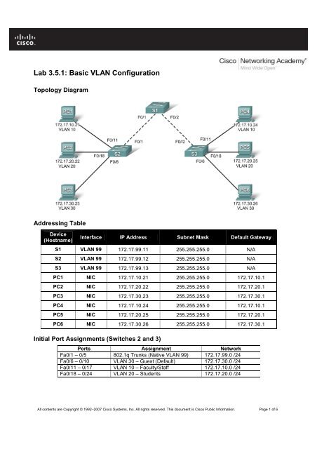
Topology Diagram<br />
Addressing Table<br />
Device<br />
(Hostname)<br />
Interface IP Address Subnet Mask Default Gateway<br />
S1 <strong>VLAN</strong> 99 172.17.99.11 255.255.255.0 N/A<br />
S2 <strong>VLAN</strong> 99 172.17.99.12 255.255.255.0 N/A<br />
S3 <strong>VLAN</strong> 99 172.17.99.13 255.255.255.0 N/A<br />
PC1 NIC 172.17.10.21 255.255.255.0 172.17.10.1<br />
PC2 NIC 172.17.20.22 255.255.255.0 172.17.20.1<br />
PC3 NIC 172.17.30.23 255.255.255.0 172.17.30.1<br />
PC4 NIC 172.17.10.24 255.255.255.0 172.17.10.1<br />
PC5 NIC 172.17.20.25 255.255.255.0 172.17.20.1<br />
PC6 NIC 172.17.30.26 255.255.255.0 172.17.30.1<br />
Initial Port Assignments (Switches 2 and 3)<br />
Ports Assignment Network<br />
Fa0/1 – 0/5 802.1q Trunks (Native <strong>VLAN</strong> 99) 172.17.99.0 /24<br />
Fa0/6 – 0/10 <strong>VLAN</strong> 30 – Guest (Default) 172.17.30.0 /24<br />
Fa0/11 – 0/17 <strong>VLAN</strong> 10 – Faculty/Staff 172.17.10.0 /24<br />
Fa0/18 – 0/24 <strong>VLAN</strong> 20 – Students 172.17.20.0 /24<br />
All contents are Copyright © 1992–2007 Cisco Systems, Inc. All rights reserved. This document is Cisco Public Information. Page 1 of 6
CCNA Exploration<br />
LAN Switching and Wireless: <strong>VLAN</strong>s <strong>Lab</strong> <strong>3.5.1</strong>: <strong>Basic</strong> <strong>VLAN</strong> <strong>Configuration</strong><br />
Learning Objectives<br />
Upon completion of this lab, you will be able to:<br />
• Cable a network according to the topology diagram<br />
• Erase the startup configuration and reload a switch to the default state<br />
• Perform basic configuration tasks on a switch<br />
• Create <strong>VLAN</strong>s<br />
• Assign switch ports to a <strong>VLAN</strong><br />
• Add, move, and change ports<br />
• Verify <strong>VLAN</strong> configuration<br />
• Enable trunking on inter-switch connections<br />
• Verify trunk configuration<br />
• Save the <strong>VLAN</strong> configuration<br />
Task 1: Prepare the Network<br />
Step 1: Cable a network that is similar to the one in the topology diagram.<br />
You can use any current switch in your lab as long as it has the required interfaces shown in the topology.<br />
Note: If you use 2900 or 2950 switches, the outputs may appear different. Also, certain commands may<br />
be different or unavailable.<br />
Step 2: Clear any existing configurations on the switches, and initialize all ports in the shutdown<br />
state.<br />
If necessary, refer to <strong>Lab</strong> 2.5.1, Appendix 1, for the procedure to clear switch configurations.<br />
It is a good practice to disable any unused ports on the switches by putting them in shutdown. Disable all<br />
ports on the switches:<br />
Switch#config term<br />
Switch(config)#interface range fa0/1-24<br />
Switch(config-if-range)#shutdown<br />
Switch(config-if-range)#interface range gi0/1-2<br />
Switch(config-if-range)#shutdown<br />
Task 2: Perform <strong>Basic</strong> Switch <strong>Configuration</strong>s<br />
Step 1: Configure the switches according to the following guidelines.<br />
• Configure the switch hostname.<br />
• Disable DNS lookup.<br />
• Configure an EXEC mode password of class.<br />
• Configure a password of cisco for console connections.<br />
• Configure a password of cisco for vty connections.<br />
Step 2: Re-enable the user ports on S2 and S3.<br />
S2(config)#interface range fa0/6, fa0/11, fa0/18<br />
S2(config-if-range)#switchport mode access<br />
All contents are Copyright © 1992–2007 Cisco Systems, Inc. All rights reserved. This document is Cisco Public Information. Page 2 of 6
CCNA Exploration<br />
LAN Switching and Wireless: <strong>VLAN</strong>s <strong>Lab</strong> <strong>3.5.1</strong>: <strong>Basic</strong> <strong>VLAN</strong> <strong>Configuration</strong><br />
S2(config-if-range)#no shutdown<br />
S3(config)#interface range fa0/6, fa0/11, fa0/18<br />
S3(config-if-range)#switchport mode access<br />
S3(config-if-range)#no shutdown<br />
Task 3: Configure and Activate Ethernet Interfaces<br />
Step 1: Configure the PCs.<br />
You can complete this lab using only two PCs by simply changing the IP addressing for the two PCs<br />
specific to a test you want to conduct. For example, if you want to test connectivity between PC1 and<br />
PC2, then configure the IP addresses for those PCs by referring to the addressing table at the beginning<br />
of the lab. Alternatively, you can configure all six PCs with the IP addresses and default gateways.<br />
Task 4: Configure <strong>VLAN</strong>s on the Switch<br />
Step 1: Create <strong>VLAN</strong>s on switch S1.<br />
Use the vlan vlan-id command in global configuration mode to add a <strong>VLAN</strong> to switch S1. There are four<br />
<strong>VLAN</strong>S configured for this lab: <strong>VLAN</strong> 10 (faculty/staff); <strong>VLAN</strong> 20 (students); <strong>VLAN</strong> 30 (guest); and <strong>VLAN</strong><br />
99 (management). After you create the <strong>VLAN</strong>, you will be in vlan configuration mode, where you can<br />
assign a name to the <strong>VLAN</strong> with the name vlan name command.<br />
S1(config)#vlan 10<br />
S1(config-vlan)#name faculty/staff<br />
S1(config-vlan)#vlan 20<br />
S1(config-vlan)#name students<br />
S1(config-vlan)#vlan 30<br />
S1(config-vlan)#name guest<br />
S1(config-vlan)#vlan 99<br />
S1(config-vlan)#name management<br />
S1(config-vlan)#end<br />
S1#<br />
Step 2: Verify that the <strong>VLAN</strong>s have been created on S1.<br />
Use the show vlan brief command to verify that the <strong>VLAN</strong>s have been created.<br />
S1#show vlan brief<br />
<strong>VLAN</strong> Name Status Ports<br />
---- ------------------------------- --------- -----------------------------<br />
1 default active Fa0/1, Fa0/2, Fa0/4, Fa0/5<br />
Fa0/6, Fa0/7, Fa0/8, Fa0/9<br />
Fa0/10, Fa0/11, Fa0/12, Fa0/13<br />
Fa0/14, Fa0/15, Fa0/16, Fa0/17<br />
Fa0/18, Fa0/19, Fa0/20, Fa0/21<br />
Fa0/22, Fa0/23, Fa0/24, Gi0/1<br />
Gi0/2<br />
10 faculty/staff active<br />
20 students active<br />
30 guest active<br />
99 management active<br />
All contents are Copyright © 1992–2007 Cisco Systems, Inc. All rights reserved. This document is Cisco Public Information. Page 3 of 6
CCNA Exploration<br />
LAN Switching and Wireless: <strong>VLAN</strong>s <strong>Lab</strong> <strong>3.5.1</strong>: <strong>Basic</strong> <strong>VLAN</strong> <strong>Configuration</strong><br />
Step 3: Configure and name <strong>VLAN</strong>s on switches S2 and S3.<br />
Create and name <strong>VLAN</strong>s 10, 20, 30, and 99 on S2 and S3 using the commands from Step 1. Verify the<br />
correct configuration with the show vlan brief command.<br />
What ports are currently assigned to the four <strong>VLAN</strong>s you have created?<br />
_______________________________<br />
Step 4: Assign switch ports to <strong>VLAN</strong>s on S2 and S3.<br />
Refer to the port assignment table on page 1. Ports are assigned to <strong>VLAN</strong>s in interface configuration<br />
mode, using the switchport access vlan vlan-id command. You can assign each port individually or you<br />
can use the interface range command to simplify this task, as shown here. The commands are shown for<br />
S3 only, but you should configure both S2 and S3 similarly. Save your configuration when done.<br />
S3(config)#interface range fa0/6-10<br />
S3(config-if-range)#switchport access vlan 30<br />
S3(config-if-range)#interface range fa0/11-17<br />
S3(config-if-range)#switchport access vlan 10<br />
S3(config-if-range)#interface range fa0/18-24<br />
S3(config-if-range)#switchport access vlan 20<br />
S3(config-if-range)#end<br />
S3#copy running-config startup-config<br />
Destination filename [startup-config]? [enter]<br />
Building configuration...<br />
[OK]<br />
Step 4: Determine which ports have been added.<br />
Use the show vlan id vlan-number command on S2 to see which ports are assigned to <strong>VLAN</strong> 10.<br />
Which ports are assigned to <strong>VLAN</strong> 10?<br />
_______________________________________________________<br />
Note: The show vlan id vlan-name displays the same output.<br />
You can also view <strong>VLAN</strong> assignment information using the show interfaces interface switchport<br />
command.<br />
Step 5: Assign the management <strong>VLAN</strong>.<br />
A management <strong>VLAN</strong> is any <strong>VLAN</strong> that you configure to access the management capabilities of a switch.<br />
<strong>VLAN</strong> 1 serves as the management <strong>VLAN</strong> if you did not specifically define another <strong>VLAN</strong>. You assign the<br />
management <strong>VLAN</strong> an IP address and subnet mask. A switch can be managed via HTTP, Telnet, SSH,<br />
or SNMP. Because the out-of-the-box configuration of a Cisco switch has <strong>VLAN</strong> 1 as the default <strong>VLAN</strong>,<br />
<strong>VLAN</strong> 1 is a bad choice as the management <strong>VLAN</strong>. You do not want an arbitrary user who is connecting<br />
to a switch to default to the management <strong>VLAN</strong>. Recall that you configured the management <strong>VLAN</strong> as<br />
<strong>VLAN</strong> 99 earlier in this lab.<br />
From interface configuration mode, use the ip address command to assign the management IP address<br />
to the switches.<br />
S1(config)#interface vlan 99<br />
S1(config-if)#ip address 172.17.99.11 255.255.255.0<br />
S1(config-if)#no shutdown<br />
S2(config)#interface vlan 99<br />
S2(config-if)#ip address 172.17.99.12 255.255.255.0<br />
S2(config-if)#no shutdown<br />
S3(config)#interface vlan 99<br />
S3(config-if)#ip address 172.17.99.13 255.255.255.0<br />
All contents are Copyright © 1992–2007 Cisco Systems, Inc. All rights reserved. This document is Cisco Public Information. Page 4 of 6
CCNA Exploration<br />
LAN Switching and Wireless: <strong>VLAN</strong>s <strong>Lab</strong> <strong>3.5.1</strong>: <strong>Basic</strong> <strong>VLAN</strong> <strong>Configuration</strong><br />
S3(config-if)#no shutdown<br />
Assigning a management address allows IP communication between the switches, and also allows any<br />
host connected to a port assigned to <strong>VLAN</strong> 99 to connect to the switches. Because <strong>VLAN</strong> 99 is<br />
configured as the management <strong>VLAN</strong>, any ports assigned to this <strong>VLAN</strong> are considered management<br />
ports and should be secured to control which devices can connect to these ports.<br />
Step 6: Configure trunking and the native <strong>VLAN</strong> for the trunking ports on all switches.<br />
Trunks are connections between the switches that allow the switches to exchange information for all<br />
<strong>VLAN</strong>S. By default, a trunk port belongs to all <strong>VLAN</strong>s, as opposed to an access port, which can only<br />
belong to a single <strong>VLAN</strong>. If the switch supports both ISL and 802.1Q <strong>VLAN</strong> encapsulation, the trunks<br />
must specify which method is being used. Because the 2960 switch only supports 802.1Q trunking, it is<br />
not specified in this lab.<br />
A native <strong>VLAN</strong> is assigned to an 802.1Q trunk port. In the topology, the native <strong>VLAN</strong> is <strong>VLAN</strong> 99. An<br />
802.1Q trunk port supports traffic coming from many <strong>VLAN</strong>s (tagged traffic) as well as traffic that does not<br />
come from a <strong>VLAN</strong> (untagged traffic). The 802.1Q trunk port places untagged traffic on the native <strong>VLAN</strong>.<br />
Untagged traffic is generated by a computer attached to a switch port that is configured with the native<br />
<strong>VLAN</strong>. One of the IEEE 802.1Q specifications for Native <strong>VLAN</strong>s is to maintain backward compatibility with<br />
untagged traffic common to legacy LAN scenarios. For the purposes of this lab, a native <strong>VLAN</strong> serves as<br />
a common identifier on opposing ends of a trunk link. It is a best practice to use a <strong>VLAN</strong> other than <strong>VLAN</strong><br />
1 as the native <strong>VLAN</strong>.<br />
Use the interface range command in global configuration mode to simplify configuring trunking.<br />
S1(config)#interface range fa0/1-5<br />
S1(config-if-range)#switchport mode trunk<br />
S1(config-if-range)#switchport trunk native vlan 99<br />
S1(config-if-range)#no shutdown<br />
S1(config-if-range)#end<br />
S2(config)# interface range fa0/1-5<br />
S2(config-if-range)#switchport mode trunk<br />
S2(config-if-range)#switchport trunk native vlan 99<br />
S2(config-if-range)#no shutdown<br />
S2(config-if-range)#end<br />
S3(config)# interface range fa0/1-5<br />
S3(config-if-range)#switchport mode trunk<br />
S3(config-if-range)#switchport trunk native vlan 99<br />
S3(config-if-range)#no shutdown<br />
S3(config-if-range)#end<br />
Verify that the trunks have been configured with the show interface trunk command.<br />
S1#show interface trunk<br />
Port Mode Encapsulation Status Native vlan<br />
Fa0/1 on 802.1q trunking 99<br />
Fa0/2 on 802.1q trunking 99<br />
Port Vlans allowed on trunk<br />
Fa0/1 1-4094<br />
Fa0/2 1-4094<br />
Port Vlans allowed and active in management domain<br />
Fa0/1 1,10,20,30,99<br />
Fa0/2 1,10,20,30,99<br />
All contents are Copyright © 1992–2007 Cisco Systems, Inc. All rights reserved. This document is Cisco Public Information. Page 5 of 6
CCNA Exploration<br />
LAN Switching and Wireless: <strong>VLAN</strong>s <strong>Lab</strong> <strong>3.5.1</strong>: <strong>Basic</strong> <strong>VLAN</strong> <strong>Configuration</strong><br />
Port Vlans in spanning tree forwarding state and not pruned<br />
Fa0/1 1,10,20,30,99<br />
Fa0/2 1,10,20,30,99<br />
Step 7: Verify that the switches can communicate.<br />
From S1, ping the management address on both S2 and S3.<br />
S1#ping 172.17.99.12<br />
Type escape sequence to abort.<br />
Sending 5, 100-byte ICMP Echos to 172.17.99.12, timeout is 2 seconds:<br />
!!!!!<br />
Success rate is 100 percent (5/5), round-trip min/avg/max = 1/2/9 ms<br />
S1#ping 172.17.99.13<br />
Type escape sequence to abort.<br />
Sending 5, 100-byte ICMP Echos to 172.17.99.13, timeout is 2 seconds:<br />
.!!!!<br />
Success rate is 80 percent (4/5), round-trip min/avg/max = 1/1/1 ms<br />
Step 8: Ping several hosts from PC2.<br />
Ping from host PC2 to host PC1 (172.17.10.21). Is the ping attempt successful? _________<br />
Ping from host PC2 to the switch <strong>VLAN</strong> 99 IP address 172.17.99.12. Is the ping attempt successful?<br />
_________<br />
Because these hosts are on different subnets and in different <strong>VLAN</strong>s, they cannot communicate without a<br />
Layer 3 device to route between the separate subnetworks.<br />
Ping from host PC2 to host PC5. Is the ping attempt successful? _________<br />
Because PC2 is in the same <strong>VLAN</strong> and the same subnet as PC5, the ping is successful<br />
Step 9: Move PC1 into the same <strong>VLAN</strong> as PC2.<br />
The port connected to PC2 (S2 Fa0/18) is assigned to <strong>VLAN</strong> 20, and the port connected to PC1 (S2<br />
Fa0/11) is assigned to <strong>VLAN</strong> 10. Reassign the S2 Fa0/11 port to <strong>VLAN</strong> 20. You do not need to first<br />
remove a port from a <strong>VLAN</strong> to change its <strong>VLAN</strong> membership. After you reassign a port to a new <strong>VLAN</strong>,<br />
that port is automatically removed from its previous <strong>VLAN</strong>.<br />
S2#configure terminal<br />
Enter configuration commands, one per line. End with CNTL/Z.<br />
S2(config)#interface fastethernet 0/11<br />
S2(config-if)#switchport access vlan 20<br />
S2(config-if)#end<br />
Ping from host PC2 to host PC1. Is the ping attempt successful? _________<br />
Even though the ports used by PC1 and PC2 are in the same <strong>VLAN</strong>, they are still in different<br />
subnetworks, so they cannot communicate directly.<br />
Step 10: Change the IP address and network on PC1.<br />
Change the IP address on PC1 to 172.17.20.22. The subnet mask and default gateway can remain the<br />
same. Once again, ping from host PC2 to host PC1, using the newly assigned IP address.<br />
Is the ping attempt successful? _________<br />
Why was this attempt successful?<br />
____________________________________________________________________________________<br />
All contents are Copyright © 1992–2007 Cisco Systems, Inc. All rights reserved. This document is Cisco Public Information. Page 6 of 6