Lab 7.4.1: Basic DHCP and NAT Configuration
Lab 7.4.1: Basic DHCP and NAT Configuration
Lab 7.4.1: Basic DHCP and NAT Configuration

You also want an ePaper? Increase the reach of your titles
YUMPU automatically turns print PDFs into web optimized ePapers that Google loves.
<strong>Lab</strong> <strong>7.4.1</strong>: <strong>Basic</strong> <strong>DHCP</strong> <strong>and</strong> <strong>NAT</strong> <strong>Configuration</strong><br />
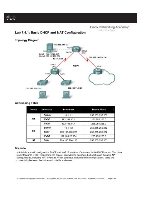
Topology Diagram<br />
Addressing Table<br />
Scenario<br />
Device Interface IP Address Subnet Mask<br />
R1<br />
R2<br />
S0/0/0 10.1.1.1 255.255.255.252<br />
Fa0/0 192.168.10.1 255.255.255.0<br />
Fa0/1 192.168.11.1 255.255.255.0<br />
S0/0/0 10.1.1.2 255.255.255.252<br />
S0/0/1 209.165.200.225 255.255.255.252<br />
Fa0/0 192.168.20.254 255.255.255.0<br />
ISP S0/0/1 209.165.200.226 255.255.255.252<br />
In this lab, you will configure the <strong>DHCP</strong> <strong>and</strong> <strong>NAT</strong> IP services. One router is the <strong>DHCP</strong> server. The other<br />
router forwards <strong>DHCP</strong> requests to the server. You will also configure both static <strong>and</strong> dynamic <strong>NAT</strong><br />
configurations, including <strong>NAT</strong> overload. When you have completed the configurations, verify the<br />
connectivity between the inside <strong>and</strong> outside addresses.<br />
All contents are Copyright © 1992–2007 Cisco Systems, Inc. All rights reserved. This document is Cisco Public Information. Page 1 of 9
CCNA Exploration<br />
Accessing the WAN: IP Addressing Services <strong>Lab</strong> <strong>7.4.1</strong>: <strong>Basic</strong> <strong>DHCP</strong> <strong>and</strong> <strong>NAT</strong> <strong>Configuration</strong><br />
Task 1: Prepare the Network<br />
Step 1: Cable a network that is similar to the one in the topology diagram.<br />
Step 2: Clear all existing configurations on the routers.<br />
Task 2: Perform <strong>Basic</strong> Router <strong>Configuration</strong>s<br />
Configure the R1, R2, <strong>and</strong> ISP routers according to the following guidelines:<br />
• Configure the device hostname.<br />
• Disable DNS lookup.<br />
• Configure a privileged EXEC mode password.<br />
• Configure a message-of-the-day banner.<br />
• Configure a password for the console connections.<br />
• Configure a password for all vty connections.<br />
• Configure IP addresses on all routers. The PCs receive IP addressing from <strong>DHCP</strong> later in the lab.<br />
• Enable OSPF with process ID 1 on R1 <strong>and</strong> R2. Do not advertise the 209.165.200.224/27<br />
network.<br />
Note: Instead of attaching a server to R2, you can configure a loopback interface on R2 to use the IP<br />
address 192.168.20.254/24. If you do this, you do not need to configure the Fast Ethernet interface.<br />
Task 3: Configure PC1 <strong>and</strong> PC2 to receive an IP address through <strong>DHCP</strong><br />
On a Windows PC go to Start -> Control Panel -> Network Connections -> Local Area Connection.<br />
Right mouse click on the Local Area Connection <strong>and</strong> select Properties.<br />
Make sure the button is selected that says Obtain an IP address automatically.<br />
Once this has been done on both PC1 <strong>and</strong> PC2, they are ready to receive an IP address from a <strong>DHCP</strong><br />
server.<br />
All contents are Copyright © 1992–2007 Cisco Systems, Inc. All rights reserved. This document is Cisco Public Information. Page 2 of 9
CCNA Exploration<br />
Accessing the WAN: IP Addressing Services <strong>Lab</strong> <strong>7.4.1</strong>: <strong>Basic</strong> <strong>DHCP</strong> <strong>and</strong> <strong>NAT</strong> <strong>Configuration</strong><br />
Task 4: Configure a Cisco IOS <strong>DHCP</strong> Server<br />
Cisco IOS software supports a <strong>DHCP</strong> server configuration called Easy IP. The goal for this lab is to have<br />
devices on the networks 192.168.10.0/24 <strong>and</strong> 192.168.11.0/24 request IP addresses via <strong>DHCP</strong> from R2.<br />
Step 1: Exclude statically assigned addresses.<br />
The <strong>DHCP</strong> server assumes that all IP addresses in a <strong>DHCP</strong> address pool subnet are available for<br />
assigning to <strong>DHCP</strong> clients. You must specify the IP addresses that the <strong>DHCP</strong> server should not assign to<br />
clients. These IP addresses are usually static addresses reserved for the router interface, switch<br />
management IP address, servers, <strong>and</strong> local network printer. The ip dhcp excluded-address comm<strong>and</strong><br />
prevents the router from assigning IP addresses within the configured range. The following comm<strong>and</strong>s<br />
exclude the first 10 IP addresses from each pool for the LANs attached to R1. These addresses will not<br />
be assigned to any <strong>DHCP</strong> clients.<br />
R2(config)#ip dhcp excluded-address 192.168.10.1 192.168.10.10<br />
R2(config)#ip dhcp excluded-address 192.168.11.1 192.168.11.10<br />
Step 2: Configure the pool.<br />
Create the <strong>DHCP</strong> pool using the ip dhcp pool comm<strong>and</strong> <strong>and</strong> name it R1Fa0.<br />
R2(config)#ip dhcp pool R1Fa0<br />
Specify the subnet to use when assigning IP addresses. <strong>DHCP</strong> pools automatically associate with an<br />
interface based on the network statement. The router now acts as a <strong>DHCP</strong> server, h<strong>and</strong>ing out addresses<br />
in the 192.168.10.0/24 subnet starting with 192.168.10.1.<br />
R2(dhcp-config)#network 192.168.10.0 255.255.255.0<br />
Configure the default router <strong>and</strong> domain name server for the network. Clients receive these settings via<br />
<strong>DHCP</strong>, along with an IP address.<br />
R2(dhcp-config)#dns-server 192.168.11.5<br />
R2(dhcp-config)#default-router 192.168.10.1<br />
Note: There is not a DNS server at 192.168.11.5. You are configuring the comm<strong>and</strong> for practice only.<br />
Because devices from the network 192.168.11.0/24 also request addresses from R2, a separate pool<br />
must be created to serve devices on that network. The comm<strong>and</strong>s are similar to the comm<strong>and</strong>s shown<br />
above:<br />
R2(config)#ip dhcp pool R1Fa1<br />
R2(dhcp-config)#network 192.168.11.0 255.255.255.0<br />
R2(dhcp-config)#dns-server 192.168.11.5<br />
R2(dhcp-config)#default-router 192.168.11.1<br />
Step 3: Test <strong>DHCP</strong><br />
On PC1 <strong>and</strong> PC2 test whether each has received an IP address automatically. On each PC go to Start -<br />
> Run -> cmd -> ipconfig -all<br />
What are the results of your test? ____________________________________<br />
Why are these the results? _________________________________________<br />
All contents are Copyright © 1992–2007 Cisco Systems, Inc. All rights reserved. This document is Cisco Public Information. Page 3 of 9
CCNA Exploration<br />
Accessing the WAN: IP Addressing Services <strong>Lab</strong> <strong>7.4.1</strong>: <strong>Basic</strong> <strong>DHCP</strong> <strong>and</strong> <strong>NAT</strong> <strong>Configuration</strong><br />
Step 4: Configure a helper address.<br />
Network services such as <strong>DHCP</strong> rely on Layer 2 broadcasts to function. When the devices providing<br />
these services exist on a different subnet than the clients, they cannot receive the broadcast packets.<br />
Because the <strong>DHCP</strong> server <strong>and</strong> the <strong>DHCP</strong> clients are not on the same subnet, configure R1 to forward<br />
<strong>DHCP</strong> broadcasts to R2, which is the <strong>DHCP</strong> server, using the ip helper-address interface configuration<br />
comm<strong>and</strong>.<br />
Notice that ip helper-address must be configured on each interface involved.<br />
R1(config)#interface fa0/0<br />
R1(config-if)#ip helper-address 10.1.1.2<br />
R1(config)#interface fa0/1<br />
R1(config-if)#ip helper-address 10.1.1.2<br />
Step 5: Release <strong>and</strong> Renew the IP addresses on PC1 <strong>and</strong> PC2<br />
Depending upon whether your PCs have been used in a different lab, or connected to the internet, they<br />
may already have learned an IP address automatically from a different <strong>DHCP</strong> server. We need to clear<br />
this IP address using the ipconfig /release <strong>and</strong> ipconfig /renew comm<strong>and</strong>s.<br />
Step 6: Verify the <strong>DHCP</strong> configuration.<br />
You can verify the <strong>DHCP</strong> server configuration in several different ways. Issue the comm<strong>and</strong> ipconfig on<br />
PC1 <strong>and</strong> PC2 to verify that they have now received an IP address dynamically. You can then issue<br />
comm<strong>and</strong>s on the router to get more information. The show ip dhcp binding comm<strong>and</strong> provides<br />
information on all currently assigned <strong>DHCP</strong> addresses. For instance, the following output shows that the<br />
IP address 192.168.10.11 has been assigned to MAC address 3031.632e.3537.6563. The IP lease<br />
expires on September 14, 2007 at 7:33 p.m.<br />
R1#show ip dhcp binding<br />
Bindings from all pools not associated with VRF:<br />
IP address Client-ID/ Lease expiration Type<br />
Hardware address/<br />
User name<br />
192.168.10.11 0063.6973.636f.2d30. Sep 14 2007 07:33 PM Automatic<br />
3031.632e.3537.6563.<br />
2e30.3634.302d.566c.<br />
31<br />
All contents are Copyright © 1992–2007 Cisco Systems, Inc. All rights reserved. This document is Cisco Public Information. Page 4 of 9
CCNA Exploration<br />
Accessing the WAN: IP Addressing Services <strong>Lab</strong> <strong>7.4.1</strong>: <strong>Basic</strong> <strong>DHCP</strong> <strong>and</strong> <strong>NAT</strong> <strong>Configuration</strong><br />
The show ip dhcp pool comm<strong>and</strong> displays information on all currently configured <strong>DHCP</strong> pools on the<br />
router. In this output, the pool R1Fa0 is configured on R1. One address has been leased from this pool.<br />
The next client to request an address will receive 192.168.10.12.<br />
R2#show ip dhcp pool<br />
Pool R1Fa0 :<br />
Utilization mark (high/low) : 100 / 0<br />
Subnet size (first/next) : 0 / 0<br />
Total addresses : 254<br />
Leased addresses : 1<br />
Pending event : none<br />
1 subnet is currently in the pool :<br />
Current index IP address range Leased addresses<br />
192.168.10.12 192.168.10.1 - 192.168.10.254 1<br />
The debug ip dhcp server events comm<strong>and</strong> can be extremely useful when troubleshooting <strong>DHCP</strong><br />
leases with a Cisco IOS <strong>DHCP</strong> server. The following is the debug output on R1 after connecting a host.<br />
Notice that the highlighted portion shows <strong>DHCP</strong> giving the client an address of 192.168.10.12 <strong>and</strong> mask<br />
of 255.255.255.0<br />
*Sep 13 21:04:18.072: <strong>DHCP</strong>D: Sending notification of DISCOVER:<br />
*Sep 13 21:04:18.072: <strong>DHCP</strong>D: htype 1 chaddr 001c.57ec.0640<br />
*Sep 13 21:04:18.072: <strong>DHCP</strong>D: remote id 020a0000c0a80b01010000000000<br />
*Sep 13 21:04:18.072: <strong>DHCP</strong>D: circuit id 00000000<br />
*Sep 13 21:04:18.072: <strong>DHCP</strong>D: Seeing if there is an internally specified pool<br />
class:<br />
*Sep 13 21:04:18.072: <strong>DHCP</strong>D: htype 1 chaddr 001c.57ec.0640<br />
*Sep 13 21:04:18.072: <strong>DHCP</strong>D: remote id 020a0000c0a80b01010000000000<br />
*Sep 13 21:04:18.072: <strong>DHCP</strong>D: circuit id 00000000<br />
*Sep 13 21:04:18.072: <strong>DHCP</strong>D: there is no address pool for 192.168.11.1.<br />
*Sep 13 21:04:18.072: <strong>DHCP</strong>D: Sending notification of DISCOVER:<br />
R1#<br />
*Sep 13 21:04:18.072: <strong>DHCP</strong>D: htype 1 chaddr 001c.57ec.0640<br />
*Sep 13 21:04:18.072: <strong>DHCP</strong>D: remote id 020a0000c0a80a01000000000000<br />
*Sep 13 21:04:18.072: <strong>DHCP</strong>D: circuit id 00000000<br />
*Sep 13 21:04:18.072: <strong>DHCP</strong>D: Seeing if there is an internally specified pool<br />
class:<br />
*Sep 13 21:04:18.072: <strong>DHCP</strong>D: htype 1 chaddr 001c.57ec.0640<br />
*Sep 13 21:04:18.072: <strong>DHCP</strong>D: remote id 020a0000c0a80a01000000000000<br />
*Sep 13 21:04:18.072: <strong>DHCP</strong>D: circuit id 00000000<br />
R1#<br />
*Sep 13 21:04:20.072: <strong>DHCP</strong>D: Adding binding to radix tree (192.168.10.12)<br />
*Sep 13 21:04:20.072: <strong>DHCP</strong>D: Adding binding to hash tree<br />
*Sep 13 21:04:20.072: <strong>DHCP</strong>D: assigned IP address 192.168.10.12 to client<br />
0063.6973.636f.2d30.3031.632e.3537.6563.2e30.3634.302d.566c.31.<br />
*Sep 13 21:04:20.072: <strong>DHCP</strong>D: Sending notification of ASSIGNMENT:<br />
*Sep 13 21:04:20.072: <strong>DHCP</strong>D: address 192.168.10.12 mask 255.255.255.0<br />
*Sep 13 21:04:20.072: <strong>DHCP</strong>D: htype 1 chaddr 001c.57ec.0640<br />
*Sep 13 21:04:20.072: <strong>DHCP</strong>D: lease time remaining (secs) = 86400<br />
*Sep 13 21:04:20.076: <strong>DHCP</strong>D: Sending notification of ASSIGNMENT:<br />
*Sep 13 21:04:20.076: <strong>DHCP</strong>D: address 192.168.10.12 mask 255.255.255.0<br />
R1#<br />
*Sep 13 21:04:20.076: <strong>DHCP</strong>D: htype 1 chaddr 001c.57ec.0640<br />
*Sep 13 21:04:20.076: <strong>DHCP</strong>D: lease time remaining (secs) = 86400<br />
All contents are Copyright © 1992–2007 Cisco Systems, Inc. All rights reserved. This document is Cisco Public Information. Page 5 of 9
CCNA Exploration<br />
Accessing the WAN: IP Addressing Services <strong>Lab</strong> <strong>7.4.1</strong>: <strong>Basic</strong> <strong>DHCP</strong> <strong>and</strong> <strong>NAT</strong> <strong>Configuration</strong><br />
Task 5: Configure Static <strong>and</strong> Default Routing<br />
ISP uses static routing to reach all networks beyond R2. However, R2 translates private addresses into<br />
public addresses before sending traffic to ISP. Therefore, ISP must be configured with the public<br />
addresses that are part of the <strong>NAT</strong> configuration on R2. Enter the following static route on ISP:<br />
ISP(config)#ip route 209.165.200.240 255.255.255.240 serial 0/0/1<br />
This static route includes all addresses assigned to R2 for public use.<br />
Configure a default route on R2 <strong>and</strong> propagate the route in OSPF.<br />
R2(config)#ip route 0.0.0.0 0.0.0.0 209.165.200.226<br />
R2(config)#router ospf 1<br />
R2(config-router)#default-information originate<br />
Allow a few seconds for R1 to learn the default route from R2 <strong>and</strong> then check the R1 routing table.<br />
Alternatively, you can clear the routing table with the clear ip route * comm<strong>and</strong>. A default route pointing<br />
to R2 should appear in the R1 routing table. From R1, ping the serial 0/0/1 interface on ISP<br />
(209.165.200.226). The pings should be successful. Troubleshoot if the pings fail.<br />
Task 6: Configure Static <strong>NAT</strong><br />
Step 1: Statically map a public IP address to a private IP address.<br />
The inside server attached to R2 is accessible by outside hosts beyond ISP. Statically assign the public<br />
IP address 209.165.200.254 as the address for <strong>NAT</strong> to use to map packets to the private IP address of<br />
the inside server at 192.168.20.254.<br />
R2(config)#ip nat inside source static 192.168.20.254 209.165.200.254<br />
Step 2: Specify inside <strong>and</strong> outside <strong>NAT</strong> interfaces.<br />
Before <strong>NAT</strong> can work, you must specify which interfaces are inside <strong>and</strong> which interfaces are outside.<br />
R2(config)#interface serial 0/0/1<br />
R2(config-if)#ip nat outside<br />
R2(config-if)#interface fa0/0<br />
R2(config-if)#ip nat inside<br />
Note: If using a simulated inside server, assign the ip nat inside comm<strong>and</strong> to the loopback interface.<br />
Step 3: Verify the static <strong>NAT</strong> configuration.<br />
From ISP, ping the public IP address 209.165.200.254.<br />
Task 7: Configure Dynamic <strong>NAT</strong> with a Pool of Addresses<br />
While static <strong>NAT</strong> provides a permanent mapping between an internal address <strong>and</strong> a specific public<br />
address, dynamic <strong>NAT</strong> maps private IP addresses to public addresses. These public IP addresses come<br />
from a <strong>NAT</strong> pool.<br />
Step 1: Define a pool of global addresses.<br />
Create a pool of addresses to which matched source addresses are translated. The following comm<strong>and</strong><br />
creates a pool named MY-<strong>NAT</strong>-POOL that translates matched addresses to an available IP address in<br />
the 209.165.200.241–209.165.200.246 range.<br />
R2(config)#ip nat pool MY-<strong>NAT</strong>-POOL 209.165.200.241 209.165.200.246 netmask<br />
255.255.255.248<br />
All contents are Copyright © 1992–2007 Cisco Systems, Inc. All rights reserved. This document is Cisco Public Information. Page 6 of 9
CCNA Exploration<br />
Accessing the WAN: IP Addressing Services <strong>Lab</strong> <strong>7.4.1</strong>: <strong>Basic</strong> <strong>DHCP</strong> <strong>and</strong> <strong>NAT</strong> <strong>Configuration</strong><br />
Step 2: Create an extended access control list to identify which inside addresses are translated.<br />
R2(config)#ip access-list extended <strong>NAT</strong><br />
R2(config-ext-nacl)#permit ip 192.168.10.0 0.0.0.255 any<br />
R2(config-ext-nacl)#permit ip 192.168.11.0 0.0.0.255 any<br />
Step 3: Establish dynamic source translation by binding the pool with the access control list.<br />
A router can have more than one <strong>NAT</strong> pool <strong>and</strong> more than one ACL. The following comm<strong>and</strong> tells the<br />
router which address pool to use to translate hosts that are allowed by the ACL.<br />
R2(config)#ip nat inside source list <strong>NAT</strong> pool MY-<strong>NAT</strong>-POOL<br />
Step 4: Specify inside <strong>and</strong> outside <strong>NAT</strong> interfaces.<br />
You have already specified the inside <strong>and</strong> outside interfaces for your static <strong>NAT</strong> configuration. Now add<br />
the serial interface linked to R1 as an inside interface.<br />
R2(config)#interface serial 0/0/0<br />
R2(config-if)#ip nat inside<br />
Step 5: Verify the configuration.<br />
Ping ISP from PC1 or the Fast Ethernet interface on R1 using extended ping. Then use the show ip nat<br />
translations <strong>and</strong> show ip nat statistics comm<strong>and</strong>s on R2 to verify <strong>NAT</strong>.<br />
R2#show ip nat translations<br />
Pro Inside global Inside local Outside local Outside global<br />
icmp 209.165.200.241:4 192.168.10.1:4 209.165.200.226:4 209.165.200.226:4<br />
--- 209.165.200.241 192.168.10.1 --- ---<br />
--- 209.165.200.254 192.168.20.254 --- ---<br />
R2#show ip nat statistics<br />
Total active translations: 2 (1 static, 1 dynamic; 0 extended)<br />
Outside interfaces:<br />
Serial0/0/1<br />
Inside interfaces:<br />
Serial0/0/0, Loopback0<br />
Hits: 23 Misses: 3<br />
CEF Translated packets: 18, CEF Punted packets: 0<br />
Expired translations: 3<br />
Dynamic mappings:<br />
-- Inside Source<br />
[Id: 1] access-list <strong>NAT</strong> pool MY-<strong>NAT</strong>-POOL refcount 1<br />
pool MY-<strong>NAT</strong>-POOL: netmask 255.255.255.248<br />
start 209.165.200.241 end 209.165.200.246<br />
type generic, total addresses 6, allocated 1 (16%), misses 0<br />
Queued Packets: 0<br />
To troubleshoot issues with <strong>NAT</strong>, you can use the debug ip nat comm<strong>and</strong>. Turn on <strong>NAT</strong> debugging <strong>and</strong><br />
repeat the ping from PC1.<br />
R2#debug ip nat<br />
IP <strong>NAT</strong> debugging is on<br />
R2#<br />
*Sep 13 21:15:02.215: <strong>NAT</strong>*: s=192.168.10.11->209.165.200.241, d=209.165.200.226 [25]<br />
*Sep 13 21:15:02.231: <strong>NAT</strong>*: s=209.165.200.226, d=209.165.200.241->192.168.10.11 [25]<br />
*Sep 13 21:15:02.247: <strong>NAT</strong>*: s=192.168.10.11->209.165.200.241, d=209.165.200.226 [26]<br />
*Sep 13 21:15:02.263: <strong>NAT</strong>*: s=209.165.200.226, d=209.165.200.241->192.168.10.11 [26]<br />
All contents are Copyright © 1992–2007 Cisco Systems, Inc. All rights reserved. This document is Cisco Public Information. Page 7 of 9
CCNA Exploration<br />
Accessing the WAN: IP Addressing Services <strong>Lab</strong> <strong>7.4.1</strong>: <strong>Basic</strong> <strong>DHCP</strong> <strong>and</strong> <strong>NAT</strong> <strong>Configuration</strong><br />
*Sep 13 21:15:02.275: <strong>NAT</strong>*: s=192.168.10.11->209.165.200.241, d=209.165.200.226 [27]<br />
*Sep 13 21:15:02.291: <strong>NAT</strong>*: s=209.165.200.226, d=209.165.200.241->192.168.10.11 [27]<br />
*Sep 13 21:15:02.307: <strong>NAT</strong>*: s=192.168.10.11->209.165.200.241, d=209.165.200.226 [28]<br />
*Sep 13 21:15:02.323: <strong>NAT</strong>*: s=209.165.200.226, d=209.165.200.241->192.168.10.11 [28]<br />
*Sep 13 21:15:02.335: <strong>NAT</strong>*: s=192.168.10.11->209.165.200.241, d=209.165.200.226 [29]<br />
*Sep 13 21:15:02.351: <strong>NAT</strong>*: s=209.165.200.226, d=209.165.200.241->192.168.10.11 [29]<br />
R2#<br />
Task 8: Configure <strong>NAT</strong> Overload<br />
In the previous example, what would happen if you needed more than the six public IP addresses that the<br />
pool allows?<br />
__________________________________________________________________________________<br />
By tracking port numbers, <strong>NAT</strong> overloading allows multiple inside users to reuse a public IP address.<br />
In this task, you will remove the pool <strong>and</strong> mapping statement configured in the previous task. Then you<br />
will configure <strong>NAT</strong> overload on R2 so that all internal IP addresses are translated to the R2 S0/0/1<br />
address when connecting to any outside device.<br />
Step 1: Remove the <strong>NAT</strong> pool <strong>and</strong> mapping statement.<br />
Use the following comm<strong>and</strong>s to remove the <strong>NAT</strong> pool <strong>and</strong> the map to the <strong>NAT</strong> ACL.<br />
R2(config)#no ip nat inside source list <strong>NAT</strong> pool MY-<strong>NAT</strong>-POOL<br />
R2(config)#no ip nat pool MY-<strong>NAT</strong>-POOL 209.165.200.241 209.165.200.246 netmask<br />
255.255.255.248<br />
If you receive the following message, clear your <strong>NAT</strong> translations.<br />
%Pool MY-<strong>NAT</strong>-POOL in use, cannot destroy<br />
R2#clear ip nat translation *<br />
Step 2: Configure PAT on R2 using the serial 0/0/1 interface public IP address.<br />
The configuration is similar to dynamic <strong>NAT</strong>, except that instead of a pool of addresses, the interface<br />
keyword is used to identify the outside IP address. Therefore, no <strong>NAT</strong> pool is defined. The overload<br />
keyword enables the addition of the port number to the translation.<br />
Because you already configured an ACL to identify which inside IP addresses to translate as well as<br />
which interfaces are inside <strong>and</strong> outside, you only need to configure the following:<br />
R2(config)#ip nat inside source list <strong>NAT</strong> interface S0/0/1 overload<br />
Step 3: Verify the configuration.<br />
Ping ISP from PC1 or the Fast Ethernet interface on R1 using extended ping. Then use the show ip nat<br />
translations <strong>and</strong> show ip nat statistics comm<strong>and</strong>s on R2 to verify <strong>NAT</strong>.<br />
R2#show ip nat translations<br />
Pro Inside global Inside local Outside local Outside global<br />
icmp 209.165.200.225:6 192.168.10.11:6 209.165.200.226:6 209.165.200.226:6<br />
--- 209.165.200.254 192.168.20.254 --- ---<br />
R2#show ip nat statistics<br />
Total active translations: 2 (1 static, 1 dynamic; 1 extended)<br />
Outside interfaces:<br />
Serial0/0/1<br />
Inside interfaces:<br />
All contents are Copyright © 1992–2007 Cisco Systems, Inc. All rights reserved. This document is Cisco Public Information. Page 8 of 9
CCNA Exploration<br />
Accessing the WAN: IP Addressing Services <strong>Lab</strong> <strong>7.4.1</strong>: <strong>Basic</strong> <strong>DHCP</strong> <strong>and</strong> <strong>NAT</strong> <strong>Configuration</strong><br />
Serial0/0/0, Loopback0<br />
Hits: 48 Misses: 6<br />
CEF Translated packets: 46, CEF Punted packets: 0<br />
Expired translations: 5<br />
Dynamic mappings:<br />
-- Inside Source<br />
[Id: 2] access-list <strong>NAT</strong> interface Serial0/0/1 refcount 1<br />
Queued Packets: 0<br />
Note: In the previous task, you could have added the keyword overload to the ip nat inside source list<br />
<strong>NAT</strong> pool MY-<strong>NAT</strong>-POOL comm<strong>and</strong> to allow for more than six concurrent users.<br />
Task 9: Clean Up<br />
Erase the configurations <strong>and</strong> reload the routers. Disconnect <strong>and</strong> store the cabling. For PC hosts that are<br />
normally connected to other networks, such as the school LAN or the Internet, reconnect the appropriate<br />
cabling <strong>and</strong> restore the TCP/IP settings.<br />
All contents are Copyright © 1992–2007 Cisco Systems, Inc. All rights reserved. This document is Cisco Public Information. Page 9 of 9