Lab 2.5.1: Basic Switch Configuration
Lab 2.5.1: Basic Switch Configuration
Lab 2.5.1: Basic Switch Configuration

Create successful ePaper yourself
Turn your PDF publications into a flip-book with our unique Google optimized e-Paper software.
<strong>Lab</strong> <strong>2.5.1</strong>: <strong>Basic</strong> <strong>Switch</strong> <strong>Configuration</strong><br />
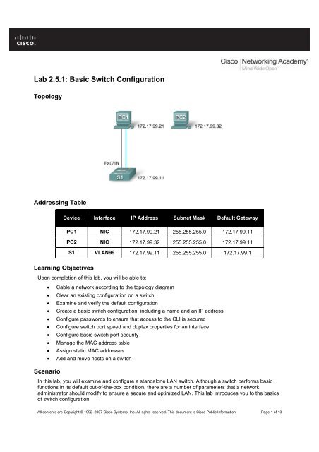
Topology<br />
Addressing Table<br />
Device Interface IP Address Subnet Mask Default Gateway<br />
Learning Objectives<br />
PC1 NIC 172.17.99.21 255.255.255.0 172.17.99.11<br />
PC2 NIC 172.17.99.32 255.255.255.0 172.17.99.11<br />
S1 VLAN99 172.17.99.11 255.255.255.0 172.17.99.1<br />
Upon completion of this lab, you will be able to:<br />
• Cable a network according to the topology diagram<br />
• Clear an existing configuration on a switch<br />
• Examine and verify the default configuration<br />
• Create a basic switch configuration, including a name and an IP address<br />
• Configure passwords to ensure that access to the CLI is secured<br />
• Configure switch port speed and duplex properties for an interface<br />
• Configure basic switch port security<br />
• Manage the MAC address table<br />
• Assign static MAC addresses<br />
• Add and move hosts on a switch<br />
Scenario<br />
In this lab, you will examine and configure a standalone LAN switch. Although a switch performs basic<br />
functions in its default out-of-the-box condition, there are a number of parameters that a network<br />
administrator should modify to ensure a secure and optimized LAN. This lab introduces you to the basics<br />
of switch configuration.<br />
All contents are Copyright © 1992–2007 Cisco Systems, Inc. All rights reserved. This document is Cisco Public Information. Page 1 of 13
CCNA Exploration<br />
LAN <strong>Switch</strong>ing and Wireless: <strong>Basic</strong> <strong>Switch</strong> Concepts and <strong>Configuration</strong> <strong>Lab</strong> <strong>2.5.1</strong>: <strong>Basic</strong> <strong>Switch</strong> <strong>Configuration</strong><br />
Task 1: Cable, Erase, and Reload the <strong>Switch</strong><br />
Step 1: Cable a network.<br />
Cable a network that is similar to the one in the topology diagram. Create a console connection to the<br />
switch.<br />
You can use any current switch in your lab as long as it has the required interfaces shown in the topology.<br />
The output shown in this lab is from a 2960 switch. If you use other switches, the switch outputs and<br />
interface descriptions may appear different.<br />
Note: PC2 is not initially connected to the switch. It is only used in Task 5.<br />
Step 2: Clear the configuration on the switch.<br />
Clear the configuration on the switch using the procedure in Appendix 1.<br />
Task 2: Verify the Default <strong>Switch</strong> <strong>Configuration</strong><br />
Step 1: Enter privileged mode.<br />
You can access all the switch commands in privileged mode. However, because many of the privileged<br />
commands configure operating parameters, privileged access should be password-protected to prevent<br />
unauthorized use. You will set passwords in Task 3.<br />
The privileged EXEC command set includes those commands contained in user EXEC mode, as well as<br />
the configure command through which access to the remaining command modes are gained. Enter<br />
privileged EXEC mode by entering the enable command.<br />
<strong>Switch</strong>>enable<br />
<strong>Switch</strong>#<br />
Notice that the prompt changed in the configuration to reflect privileged EXEC mode.<br />
Step 2: Examine the current switch configuration.<br />
Examine the current running configuration file.<br />
<strong>Switch</strong>#show running-config<br />
How many Fast Ethernet interfaces does the switch have? _______________________<br />
How many Gigabit Ethernet interfaces does the switch have? _____________________<br />
What is the range of values shown for the vty lines? ____________________________<br />
Examine the current contents of NVRAM:<br />
<strong>Switch</strong>#show startup-config<br />
startup-config is not present<br />
Why does the switch give this response?<br />
______________________________________________________________________<br />
Examine the characteristics of the virtual interface VLAN1:<br />
<strong>Switch</strong>#show interface vlan1<br />
All contents are Copyright © 1992–2007 Cisco Systems, Inc. All rights reserved. This document is Cisco Public Information. Page 2 of 13
CCNA Exploration<br />
LAN <strong>Switch</strong>ing and Wireless: <strong>Basic</strong> <strong>Switch</strong> Concepts and <strong>Configuration</strong> <strong>Lab</strong> <strong>2.5.1</strong>: <strong>Basic</strong> <strong>Switch</strong> <strong>Configuration</strong><br />
Is there an IP address set on the switch? __________________________________<br />
What is the MAC address of this virtual switch interface? ______________________<br />
Is this interface up? ___________________________________________________<br />
Now view the IP properties of the interface:<br />
<strong>Switch</strong>#show ip interface vlan1<br />
What output do you see? _________________________________________________________<br />
Step 3: Display Cisco IOS information.<br />
Examine the following version information that the switch reports.<br />
<strong>Switch</strong>#show version<br />
What is the Cisco IOS version that the switch is running? _______________________<br />
What is the system image filename? ________________________________________<br />
What is the base MAC address of this switch? _________________________________<br />
Step 4: Examine the Fast Ethernet interfaces.<br />
Examine the default properties of the Fast Ethernet interface used by PC1.<br />
<strong>Switch</strong>#show interface fastethernet 0/18<br />
Is the interface up or down? ______________________________________<br />
What event would make an interface go up? _________________________<br />
What is the MAC address of the interface? __________________________<br />
What is the speed and duplex setting of the interface? _________________<br />
Step 5: Examine VLAN information.<br />
Examine the default VLAN settings of the switch.<br />
<strong>Switch</strong>#show vlan<br />
What is the name of VLAN 1? ________________________________<br />
Which ports are in this VLAN? __________________________<br />
Is VLAN 1 active? _________________________________________________<br />
What type of VLAN is the default VLAN? ______________________________<br />
Step 6 Examine flash memory.<br />
Issue one of the following commands to examine the contents of the flash directory.<br />
<strong>Switch</strong>#dir flash:<br />
or<br />
<strong>Switch</strong>#show flash<br />
Which files or directories are found?<br />
____________________________________________________________________________________<br />
All contents are Copyright © 1992–2007 Cisco Systems, Inc. All rights reserved. This document is Cisco Public Information. Page 3 of 13
CCNA Exploration<br />
LAN <strong>Switch</strong>ing and Wireless: <strong>Basic</strong> <strong>Switch</strong> Concepts and <strong>Configuration</strong> <strong>Lab</strong> <strong>2.5.1</strong>: <strong>Basic</strong> <strong>Switch</strong> <strong>Configuration</strong><br />
Files have a file extension, such as .bin, at the end of the filename. Directories do not have a file<br />
extension. To examine the files in a directory, issue the following command using the filename displayed<br />
in the output of the previous command:<br />
<strong>Switch</strong>#dir flash:c2960-lanbase-mz.122-25.SEE3<br />
The output should look similar to this:<br />
Directory of flash:/c2960-lanbase-mz.122-25.SEE3/<br />
6 drwx 4480 Mar 1 1993 00:04:42 +00:00 html<br />
618 -rwx 4671175 Mar 1 1993 00:06:06 +00:00 c2960-lanbase-mz.122-25.SEE3.bin<br />
619 -rwx 457 Mar 1 1993 00:06:06 +00:00 info<br />
32514048 bytes total (24804864 bytes free)<br />
What is the name of the Cisco IOS image file? ______________________________________________<br />
Step 7: Examine the startup configuration file.<br />
To view the contents of the startup configuration file, issue the show startup-config command in<br />
privileged EXEC mode.<br />
<strong>Switch</strong>#show startup-config<br />
startup-config is not present<br />
Why does this message appear? ______________________________________________________<br />
Let’s make one configuration change to the switch and then save it. Type the following commands:<br />
<strong>Switch</strong>#configure terminal<br />
Enter configuration commands, one per line. End with CNTL/Z.<br />
<strong>Switch</strong>(config)#hostname S1<br />
S1(config)#exit<br />
S1#<br />
To save the contents of the running configuration file to non-volatile RAM (NVRAM), issue the the<br />
command copy running-config startup-config.<br />
<strong>Switch</strong>#copy running-config startup-config<br />
Destination filename [startup-config]? (enter)<br />
Building configuration...<br />
[OK]<br />
Note: This command is easier to enter by using the copy run start abbreviation.<br />
Now display the contents of NVRAM using the show startup-config command.<br />
S1#show startup-config<br />
Using 1170 out of 65536 bytes<br />
!<br />
version 12.2<br />
no service pad<br />
service timestamps debug uptime<br />
service timestamps log uptime<br />
no service password-encryption<br />
!<br />
hostname S1<br />
!<br />
<br />
All contents are Copyright © 1992–2007 Cisco Systems, Inc. All rights reserved. This document is Cisco Public Information. Page 4 of 13
CCNA Exploration<br />
LAN <strong>Switch</strong>ing and Wireless: <strong>Basic</strong> <strong>Switch</strong> Concepts and <strong>Configuration</strong> <strong>Lab</strong> <strong>2.5.1</strong>: <strong>Basic</strong> <strong>Switch</strong> <strong>Configuration</strong><br />
The current configuration has been written to NVRAM.<br />
Task 3: Create a <strong>Basic</strong> <strong>Switch</strong> <strong>Configuration</strong><br />
Step 1: Assign a name to the switch.<br />
In the last step of the previous task, you configured the hostname. Here's a review of the commands<br />
used.<br />
S1#configure terminal<br />
S1(config)#hostname S1<br />
S1(config)#exit<br />
Step 2: Set the access passwords.<br />
Enter config-line mode for the console. Set the login password to cisco. Also configure the vty lines 0 to<br />
15 with the password cisco.<br />
S1#configure terminal<br />
Enter the configuration commands, one for each line. When you are finished,<br />
return to global configuration mode by entering the exit command or pressing<br />
Ctrl-Z.<br />
S1(config)#line console 0<br />
S1(config-line)#password cisco<br />
S1(config-line)#login<br />
S1(config-line)#line vty 0 15<br />
S1(config-line)#password cisco<br />
S1(config-line)#login<br />
S1(config-line)#exit<br />
Why is the login command required? _____________________________________________________<br />
Step 3. Set the command mode passwords.<br />
Set the enable secret password to class. This password protects access to privileged EXEC mode.<br />
S1(config)#enable secret class<br />
Step 4. Configure the Layer 3 address of the switch.<br />
Before you can manage S1 remotely from PC1, you need to assign the switch an IP address. The default<br />
configuration on the switch is to have the management of the switch controlled through VLAN 1.<br />
However, a best practice for basic switch configuration is to change the management VLAN to a VLAN<br />
other than VLAN 1. The implications and reasoning behind this action are explained in the next chapter.<br />
For management purposes, we will use VLAN 99. The selection of VLAN 99 is arbitrary and in no way<br />
implies you should always use VLAN 99.<br />
First, you will create the new VLAN 99 on the switch. Then you will set the IP address of the switch to<br />
172.17.99.11 with a subnet mask of 255.255.255.0 on the internal virtual interface VLAN 99.<br />
S1(config)#vlan 99<br />
S1(config-vlan)#exit<br />
S1(config)#interface vlan99<br />
%LINEPROTO-5-UPDOWN: Line protocol on Interface Vlan99, changed state to down<br />
S1(config-if)#ip address 172.17.99.11 255.255.255.0<br />
S1(config-if)#no shutdown<br />
All contents are Copyright © 1992–2007 Cisco Systems, Inc. All rights reserved. This document is Cisco Public Information. Page 5 of 13
CCNA Exploration<br />
LAN <strong>Switch</strong>ing and Wireless: <strong>Basic</strong> <strong>Switch</strong> Concepts and <strong>Configuration</strong> <strong>Lab</strong> <strong>2.5.1</strong>: <strong>Basic</strong> <strong>Switch</strong> <strong>Configuration</strong><br />
S1(config-if)#exit<br />
S1(config)#<br />
Notice that the VLAN 99 interface is in the down state even though you entered the command no<br />
shutdown. The interface is currently down because no switchports are assigned to VLAN 99.<br />
Assign all user ports to VLAN 99.<br />
S1#configure terminal<br />
S1(config)#interface range fa0/1 - 24<br />
S1(config-if-range)#switchport access vlan 99<br />
S1(config-if-range)#exit<br />
S1(config-if-range)#<br />
%LINEPROTO-5-UPDOWN: Line protocol on Interface Vlan1, changed state to down<br />
%LINEPROTO-5-UPDOWN: Line protocol on Interface Vlan99, changed state to up<br />
It is beyond the scope of this lab to fully explore VLANs. This subject is discussed in greater detail in the<br />
next chapter. However, to establish connectivity between the host and the switch, the ports used by the<br />
host must be in the same VLAN as the switch. Notice in the above output that VLAN 1 interface goes<br />
down because none of the ports are assigned to VLAN 1. After a few seconds, VLAN 99 will come up<br />
because at least one port is now assigned to VLAN 99.<br />
Step 5: Set the switch default gateway.<br />
S1 is a layer 2 switch, so it makes forwarding decisions based on the Layer 2 header. If multiple networks<br />
are connected to a switch, you need to specify how the switch forwards the internetwork frames, because<br />
the path must be determined at Layer three. This is done by specifying a default gateway address that<br />
points to a router or Layer 3 switch. Although this activity does not include an external IP gateway,<br />
assume that you will eventually connect the LAN to a router for external access. Assuming that the LAN<br />
interface on the router is 172.17.99.1, set the default gateway for the switch.<br />
S1(config)#ip default-gateway 172.17.99.1<br />
S1(config)#exit<br />
Step 6: Verify the management LANs settings.<br />
Verify the interface settings on VLAN 99.<br />
S1#show interface vlan 99<br />
What is the bandwidth on this interface? ______________________________<br />
What are the VLAN states? VLAN1 is ______________ Line protocol is ______________<br />
What is the queuing strategy? ____________________<br />
Step 7: Configure the IP address and default gateway for PC1.<br />
Set the IP address of PC1 to 172.17.99.21, with a subnet mask of 255.255.255.0. Configure a default<br />
gateway of 172.17.99.11. (If needed, refer to <strong>Lab</strong> 1.3.1 to configure the PC NIC.)<br />
Step 8: Verify connectivity.<br />
To verify the host and switch are correctly configured, ping the IP address of the switch (172.17.99.11)<br />
from PC1.<br />
Was the ping successful? ________________________<br />
If not, troubleshoot the switch and host configuration. Note that this may take a couple of tries for the<br />
pings to succeed.<br />
All contents are Copyright © 1992–2007 Cisco Systems, Inc. All rights reserved. This document is Cisco Public Information. Page 6 of 13
CCNA Exploration<br />
LAN <strong>Switch</strong>ing and Wireless: <strong>Basic</strong> <strong>Switch</strong> Concepts and <strong>Configuration</strong> <strong>Lab</strong> <strong>2.5.1</strong>: <strong>Basic</strong> <strong>Switch</strong> <strong>Configuration</strong><br />
Step 9: Configure the port speed and duplex settings for a Fast Ethernet interface.<br />
Configure the duplex and speed settings on Fast Ethernet 0/18. Use the end command to return to<br />
privileged EXEC mode when finished.<br />
S1#configure terminal<br />
S1(config)#interface fastethernet 0/18<br />
S1(config-if)#speed 100<br />
S1(config-if)#duplex full<br />
S1(config-if)#end<br />
%LINEPROTO-5-UPDOWN: Line protocol on Interface FastEthernet0/18, changed<br />
state to down<br />
%LINEPROTO-5-UPDOWN: Line protocol on Interface Vlan99, changed state to down<br />
%LINK-3-UPDOWN: Interface FastEthernet0/18, changed state to down<br />
%LINK-3-UPDOWN: Interface FastEthernet0/18, changed state to up<br />
%LINEPROTO-5-UPDOWN: Line protocol on Interface FastEthernet0/18, changed<br />
state to up<br />
%LINEPROTO-5-UPDOWN: Line protocol on Interface Vlan99, changed state to up<br />
The line protocol for both interface FastEthernet 0/18 and interface VLAN 99 will temporarily go down.<br />
The default on the Ethernet interface of the switch is auto-sensing, so it automatically negotiates optimal<br />
settings. You should set duplex and speed manually only if a port must operate at a certain speed and<br />
duplex mode. Manually configuring ports can lead to duplex mismatches, which can significantly degrade<br />
performance.<br />
Verify the new duplex and speed settings on the Fast Ethernet interface.<br />
S1#show interface fastethernet 0/18<br />
Step 10: Save the configuration.<br />
You have completed the basic configuration of the switch. Now back up the running configuration file to<br />
NVRAM to ensure that the changes made will not be lost if the system is rebooted or loses power.<br />
S1#copy running-config startup-config<br />
Destination filename [startup-config]?[Enter] Building configuration...<br />
[OK]<br />
S1#<br />
Step 11: Examine the startup configuration file.<br />
To see the configuration that is stored in NVRAM, issue the show startup-config command from<br />
privileged EXEC mode.<br />
S1#show startup-config<br />
Are all the changes that were entered recorded in the file? ______________<br />
Task 4: Managing the MAC Address Table<br />
Step 1: Record the MAC addresses of the hosts.<br />
Determine and record the Layer 2 (physical) addresses of the PC network interface cards using the<br />
following commands:<br />
Start > Run > cmd > ipconfig /all<br />
PC1: ___________________________________________________________________<br />
All contents are Copyright © 1992–2007 Cisco Systems, Inc. All rights reserved. This document is Cisco Public Information. Page 7 of 13
CCNA Exploration<br />
LAN <strong>Switch</strong>ing and Wireless: <strong>Basic</strong> <strong>Switch</strong> Concepts and <strong>Configuration</strong> <strong>Lab</strong> <strong>2.5.1</strong>: <strong>Basic</strong> <strong>Switch</strong> <strong>Configuration</strong><br />
PC2: ___________________________________________________________________<br />
Step 2: Determine the MAC addresses that the switch has learned.<br />
Display the MAC addresses using the show mac-address-table command in privileged EXEC mode.<br />
S1#show mac-address-table<br />
How many dynamic addresses are there? _______________________________<br />
How many MAC addresses are there in total? ____________________________<br />
Do the dynamic MAC addresses match the host MAC addresses? _____________________<br />
Step 3: List the show mac-address-table options.<br />
S1#show mac-address-table ?<br />
How many options are available for the show mac-address-table command? ________<br />
Show only the MAC addresses from the table that were learned dynamically.<br />
S1#show mac-address-table address <br />
How many dynamic addresses are there? _________________<br />
Step 4: Clear the MAC address table.<br />
To remove the existing MAC addresses, use the clear mac-address-table command from privileged<br />
EXEC mode.<br />
S1#clear mac-address-table dynamic<br />
Step 5: Verify the results.<br />
Verify that the MAC address table was cleared.<br />
S1#show mac-address-table<br />
How many static MAC addresses are there? ___________________________________ How many<br />
dynamic addresses are there? _____________________________________<br />
Step 6: Examine the MAC table again.<br />
More than likely, an application running on your PC1 has already sent a frame out the NIC to S1. Look at<br />
the MAC address table again in privileged EXEC mode to see if S1 has relearned the MAC address for<br />
PC1<br />
S1#show mac-address-table<br />
How many dynamic addresses are there? ________________________________<br />
Why did this change from the last display? _____________________________________________<br />
_______________________________________________________________________________ If S1<br />
has not yet relearned the MAC address for PC1, ping the VLAN 99 IP address of the switch from PC1<br />
and then repeat Step 6.<br />
All contents are Copyright © 1992–2007 Cisco Systems, Inc. All rights reserved. This document is Cisco Public Information. Page 8 of 13
CCNA Exploration<br />
LAN <strong>Switch</strong>ing and Wireless: <strong>Basic</strong> <strong>Switch</strong> Concepts and <strong>Configuration</strong> <strong>Lab</strong> <strong>2.5.1</strong>: <strong>Basic</strong> <strong>Switch</strong> <strong>Configuration</strong><br />
Step 7: Set up a static MAC address.<br />
To specify which ports a host can connect to, one option is to create a static mapping of the host MAC<br />
address to a port.<br />
Set up a static MAC address on Fast Ethernet interface 0/18 using the address that was recorded for PC1<br />
in Step 1 of this task. The MAC address 00e0.2917.1884 is used as an example only. You must use the<br />
MAC address of your PC1, which is different than the one given here as an example.<br />
S1(config)#mac-address-table static 00e0.2917.1884 interface fastethernet<br />
0/18 vlan 99<br />
Step 8: Verify the results.<br />
Verify the MAC address table entries.<br />
S1#show mac-address-table<br />
How many total MAC addresses are there? ______________________________________ How many<br />
static addresses are there? __________________________________________<br />
Step 10: Remove the static MAC entry.<br />
To complete the next task, it will be necessary to remove the static MAC address table entry. Enter<br />
configuration mode and remove the command by putting a no in front of the command string.<br />
Note: The MAC address 00e0.2917.1884 is used in the example only. Use the MAC address for your<br />
PC1.<br />
S1(config)#no mac-address-table static 00e0.2917.1884 interface fastethernet<br />
0/18 vlan 99<br />
Step 10: Verify the results.<br />
Verify that the static MAC address has been cleared.<br />
S1#show mac-address-table<br />
How many total static MAC addresses are there? _______________________________<br />
Task 5 Configuring Port Security<br />
Step 1: Configure a second host.<br />
A second host is needed for this task. Set the IP address of PC2 to 172.17.99.32, with a subnet mask of<br />
255.255.255.0 and a default gateway of 172.17.99.11. Do not connect this PC to the switch yet.<br />
Step 2: Verify connectivity.<br />
Verify that PC1 and the switch are still correctly configured by pinging the VLAN 99 IP address of the<br />
switch from the host.<br />
Were the pings successful? _____________________________________<br />
If the answer is no, troubleshoot the host and switch configurations.<br />
Step 3: Copy the host MAC addresses.<br />
Write down the MAC addresses from Task 4, Step 1.<br />
All contents are Copyright © 1992–2007 Cisco Systems, Inc. All rights reserved. This document is Cisco Public Information. Page 9 of 13
CCNA Exploration<br />
LAN <strong>Switch</strong>ing and Wireless: <strong>Basic</strong> <strong>Switch</strong> Concepts and <strong>Configuration</strong> <strong>Lab</strong> <strong>2.5.1</strong>: <strong>Basic</strong> <strong>Switch</strong> <strong>Configuration</strong><br />
PC1____________________________________________________________________<br />
PC2____________________________________________________________________<br />
Step 4: Determine which MAC addresses that the switch has learned.<br />
Display the learned MAC addresses using the show mac-address-table command in privileged EXEC<br />
mode.<br />
S1#show mac-address-table<br />
How many dynamic addresses are there? ___________________________________<br />
Do the MAC addresses match the host MAC addresses? ______________________<br />
Step 5: List the port security options.<br />
Explore the options for setting port security on interface Fast Ethernet 0/18.<br />
S1# configure terminal<br />
S1(config)#interface fastethernet 0/18<br />
S1(config-if)#switchport port-security ?<br />
aging Port-security aging commands<br />
mac-address Secure mac address<br />
maximum Max secure addresses<br />
violation Security violation mode<br />
<br />
S1(config-if)#switchport port-security<br />
Step 6: Configure port security on an access port.<br />
Configure switch port Fast Ethernet 0/18 to accept only two devices, to learn the MAC addresses of those<br />
devices dynamically, and to block traffic from invalid hosts if a violation occurs.<br />
S1(config-if)#switchport mode access<br />
S1(config-if)#switchport port-security<br />
S1(config-if)#switchport port-security maximum 2<br />
S1(config-if)#switchport port-security mac-address sticky<br />
S1(config-if)#switchport port-security violation protect<br />
S1(config-if)#exit<br />
Step 7: Verify the results.<br />
Show the port security settings.<br />
S1#show port-security<br />
How many secure addresses are allowed on Fast Ethernet 0/18?__________________<br />
What is the security action for this port? ______________________________________<br />
Step 8: Examine the running configuration file.<br />
S1#show running-config<br />
Are there statements listed that directly reflect the security implementation of the running configuration?<br />
____________________________________________________<br />
All contents are Copyright © 1992–2007 Cisco Systems, Inc. All rights reserved. This document is Cisco Public Information. Page 10 of 13
CCNA Exploration<br />
LAN <strong>Switch</strong>ing and Wireless: <strong>Basic</strong> <strong>Switch</strong> Concepts and <strong>Configuration</strong> <strong>Lab</strong> <strong>2.5.1</strong>: <strong>Basic</strong> <strong>Switch</strong> <strong>Configuration</strong><br />
Step 9: Modify the port security settings on a port.<br />
On interface Fast Ethernet 0/18, change the port security maximum MAC address count to 1 and to shut<br />
down if a violation occurs.<br />
S1(config-if)#switchport port-security maximum 1<br />
S1(config-if)#switchport port-security violation shutdown<br />
Step 10: Verify the results.<br />
Show the port security settings.<br />
S1#show port-security<br />
Have the port security settings changed to reflect the modifications in Step 9? ___________<br />
Ping the VLAN 99 address of the switch from PC1 to verify connectivity and to refresh the MAC address<br />
table. You should now see the MAC address for PC1 “stuck” to the running configuration.<br />
S1#show run<br />
Building configuration...<br />
<br />
!<br />
interface FastEthernet0/18<br />
switchport access vlan 99<br />
switchport mode access<br />
switchport port-security<br />
switchport port-security mac-address sticky<br />
switchport port-security mac-address sticky 00e0.2917.1884<br />
speed 100<br />
duplex full<br />
!<br />
<br />
Step 11: Introduce a rogue host.<br />
Disconnect PC1 and connect PC2 to port Fast Ethernet 0/18. Ping the VLAN 99 address 172.17.99.11<br />
from the new host. Wait for the amber link light to turn green. Once it turns green, it should almost<br />
immediately turn off.<br />
Record any observations: ____________________________________________________________<br />
_________________________________________________________________________________<br />
Step 12: Show port configuration information.<br />
To see the configuration information for just Fast Ethernet port 0/18, issue the following command in<br />
privileged EXEC mode:<br />
S1#show interface fastethernet 0/18<br />
What is the state of this interface?<br />
Fast Ethernet0/18 is ______________ Line protocol is _______________<br />
Step 13: Reactivate the port.<br />
If a security violation occurs and the port is shut down, you can use the no shutdown command to<br />
reactivate it. However, as long as the rogue host is attached to Fast Ethernet 0/18, any traffic from the<br />
All contents are Copyright © 1992–2007 Cisco Systems, Inc. All rights reserved. This document is Cisco Public Information. Page 11 of 13
CCNA Exploration<br />
LAN <strong>Switch</strong>ing and Wireless: <strong>Basic</strong> <strong>Switch</strong> Concepts and <strong>Configuration</strong> <strong>Lab</strong> <strong>2.5.1</strong>: <strong>Basic</strong> <strong>Switch</strong> <strong>Configuration</strong><br />
host disables the port. Reconnect PC1 to Fast Ethernet 0/18, and enter the following commands on the<br />
switch:<br />
S1# configure terminal<br />
S1(config)#interface fastethernet 0/18<br />
S1(config-if)# no shutdown<br />
S1(config-if)#exit<br />
Note: Some IOS version may require a manual shutdown command before entering the no shutdown<br />
command.<br />
Step 14: Cleanup<br />
Unless directed otherwise, clear the configuration on the switches, turn off the power to the host computer<br />
and switches, and remove and store the cables.<br />
Appendix 1<br />
Erasing and Reloading the <strong>Switch</strong><br />
For the majority of the labs in Exploration 3, it is necessary to start with an unconfigured switch. Using a<br />
switch with an existing configuration may produce unpredictable results. These instructions show you how<br />
to prepare the switch prior to starting the lab. These instructions are for the 2960 switch; however, the<br />
procedure for the 2900 and 2950 switches is the same.<br />
Step 1: Enter privileged EXEC mode by typing the enable command.<br />
If prompted for a password, enter class. If that does not work, ask the instructor.<br />
<strong>Switch</strong>>enable<br />
Step 2: Remove the VLAN database information file.<br />
<strong>Switch</strong>#delete flash:vlan.dat<br />
Delete filename [vlan.dat]?[Enter]<br />
Delete flash:vlan.dat? [confirm] [Enter]<br />
If there is no VLAN file, this message is displayed:<br />
%Error deleting flash:vlan.dat (No such file or directory)<br />
Step 3: Remove the switch startup configuration file from NVRAM.<br />
<strong>Switch</strong>#erase startup-config<br />
The responding line prompt will be:<br />
Erasing the nvram filesystem will remove all files! Continue? [confirm]<br />
Press Enter to confirm.<br />
The response should be:<br />
Erase of nvram: complete<br />
Step 4: Check that the VLAN information was deleted.<br />
Verify that the VLAN configuration was deleted in Step 2 using the show vlan command.<br />
If the VLAN information was successfully deleted in Step 2, go to Step 5 and restart the switch using the<br />
reload command.<br />
All contents are Copyright © 1992–2007 Cisco Systems, Inc. All rights reserved. This document is Cisco Public Information. Page 12 of 13
CCNA Exploration<br />
LAN <strong>Switch</strong>ing and Wireless: <strong>Basic</strong> <strong>Switch</strong> Concepts and <strong>Configuration</strong> <strong>Lab</strong> <strong>2.5.1</strong>: <strong>Basic</strong> <strong>Switch</strong> <strong>Configuration</strong><br />
If previous VLAN configuration information is still present (other than the default management VLAN 1),<br />
you must power-cycle the switch (hardware restart ) instead of issuing the reload command. To powercycle<br />
the switch, remove the power cord from the back of the switch or unplug it, and then plug it back in.<br />
Step 5: Restart the software.<br />
Note: This step is not necessary if the switch was restarted using the power-cycle method.<br />
At the privileged EXEC mode prompt, enter the reload command.<br />
<strong>Switch</strong>(config)#reload<br />
The responding line prompt will be:<br />
System configuration has been modified. Save? [yes/no]:<br />
Type n and then press Enter.<br />
The responding line prompt will be:<br />
Proceed with reload? [confirm] [Enter]<br />
The first line of the response will be:<br />
Reload requested by console.<br />
After the switch has reloaded, the line prompt will be:<br />
Would you like to enter the initial configuration dialog? [yes/no]:<br />
Type n and then press Enter.<br />
The responding line prompt will be:<br />
Press RETURN to get started! [Enter]<br />
All contents are Copyright © 1992–2007 Cisco Systems, Inc. All rights reserved. This document is Cisco Public Information. Page 13 of 13