L33-L38 Nios II Interrupts without LQuiz - Courses
L33-L38 Nios II Interrupts without LQuiz - Courses
L33-L38 Nios II Interrupts without LQuiz - Courses

Create successful ePaper yourself
Turn your PDF publications into a flip-book with our unique Google optimized e-Paper software.
<strong>Nios</strong> <strong>II</strong> CPU Interrupt Details<br />
(revised 3/28/2011)<br />
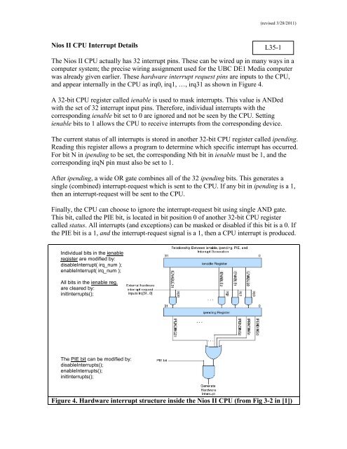
The <strong>Nios</strong> <strong>II</strong> CPU actually has 32 interrupt pins. These can be wired up in many ways in a<br />
computer system; the precise wiring assignment used for the UBC DE1 Media computer<br />
was already given earlier. These hardware interrupt request pins are inputs to the CPU,<br />
and appear internally in the CPU as irq0, irq1, …, irq31 as shown in Figure 4.<br />
A 32-bit CPU register called ienable is used to mask interrupts. This value is ANDed<br />
with the set of 32 interrupt input pins. Therefore, individual interrupts with the<br />
corresponding ienable bit set to 0 are ignored and not be seen by the CPU. Setting<br />
ienable bits to 1 allows the CPU to receive interrupts from the corresponding device.<br />
The current status of all interrupts is stored in another 32-bit CPU register called ipending.<br />
Reading this register allows a program to determine which specific interrupt has occurred.<br />
For bit N in ipending to be set, the corresponding Nth bit in ienable must be 1, and the<br />
corresponding irqN pin must also be set to 1.<br />
After ipending, a wide OR gate combines all of the 32 ipending bits. This generates a<br />
single (combined) interrupt-request which is sent to the CPU. If any bit in ipending is a 1,<br />
then an interrupt-request will be sent to the CPU.<br />
Finally, the CPU can choose to ignore the interrupt-request bit using single AND gate.<br />
This bit, called the PIE bit, is located in bit position 0 of another 32-bit CPU register<br />
called status. All interrupts (and exceptions) can be masked or disabled if this bit is a 0. If<br />
the PIE bit is a 1, and the interrupt-request signal is a 1, then a CPU interrupt is produced.<br />
Individual bits in the ienable<br />
register are modified by:<br />
disableInterrupt( irq_num );<br />
enableInterrupt( irq_num );<br />
All bits in the ienable reg.<br />
are cleared by:<br />
init<strong>Interrupts</strong>();<br />
The PIE bit can be modified by:<br />
disable<strong>Interrupts</strong>();<br />
enable<strong>Interrupts</strong>();<br />
init<strong>Interrupts</strong>();<br />
L35-1<br />
Figure 4. Hardware interrupt structure inside the <strong>Nios</strong> <strong>II</strong> CPU (from Fig 3-2 in [1])