April - Library
April - Library
April - Library

You also want an ePaper? Increase the reach of your titles
YUMPU automatically turns print PDFs into web optimized ePapers that Google loves.
Protection Of Drives<br />
Alltec Corporation www.allteccorp.com (USA)<br />
Surge Protection Devices (SPDs)<br />
Sophisticated and highly susceptible microprocessor based electronics and data communication networks are<br />
integrated across every sector of today’s fast paced business world. Preserving these mission-critical systems<br />
from the damages of surges, spikes, and transients ensures that these systems are protected from equipment<br />
destruction, disruption in service, and from costly downtime. How to properly stage these SPDs can be as important<br />
as actually making the decision to purchase them.<br />
Protection of Drives<br />
The use of various types of drives to control motors is very common. The purpose of the drive is to increase<br />
the efficiency or to manage the speed of the motor being controlled. Through various processes and control<br />
mechanisms, the drive often reshapes the sinewave to provide a signal to the motor that allows for greater<br />
efficiency or varies the frequency of the signal to control the speed of the motor. Due to the action of the drive, the<br />
power quality of the electrical environment can be compromised. That is, the drives can create voltage surges and<br />
harmonics on the system.<br />
There are various technologies available that aid in correcting these issues. This application note focuses on<br />
applying surge protective devices (SPDs) to a drive system to mitigate the damage that can occur due to voltage<br />
surges while considering the effects of the harmonics on the surge protective device.<br />
Application of SPDs<br />
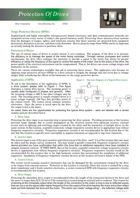
Figure 1 One Line Diagram of a Typical Drive Layout<br />
To aid in the description of the application of SPDs to<br />
a drive system, please refer to Figure 1. This figure<br />
illustrates a typical drive layout. The incoming power is<br />
usually delta configured (3 phases and ground). Often<br />
the incoming voltage is 480 V, but other voltages may be<br />
used. The incoming power is usually stepped down to a<br />
lower voltage (typically 120 Vac) that provides power to<br />
the control circuit. The control circuit contains sensitive<br />
electronics. Once the power is acted upon by the drive<br />
the output is fed to the motor.<br />
As noted, there are five opportunities for protecting the typical drive system – each are labeled with a circled<br />
number and are described below.<br />
1. Drive Input.<br />
Protecting the drive input is an essential step in protecting the drive system. Providing protection at this location<br />
prevents surge damage due to events propagated on the electrical system from upstream sources, external<br />
events such as lightning and switching surges created by the utility, and the interaction of multiple drives on the<br />
same system. At this location, a parallel connected, voltage responsive circuitry device is appropriate (one without<br />
frequency responsive circuitry). Frequency responsive circuitry is not recommended for this location due to the<br />
fact that this location is typically more susceptible to impulse transients as opposed to ring wave transients.<br />
2. Inverter Input.<br />
The inverter input is one of the most sensitive and critical areas of the drive itself. It is at this location that care must<br />
be taken and the proper survey conducted. You may install a parallel connected, frequency responsive circuitry<br />
device provided you have confirmation that within this drive that no additional capacitors have been installed to<br />
mitigate harmonic currents. IF THEY HAVE, then at this location, a parallel connected, voltage responsive circuitry<br />
device is appropriate (one without frequency responsive circuitry). Frequency responsive circuitry would not be<br />
recommended for this location due to the high harmonic content that necessitated the installation of additional<br />
capacitors. Installation of frequency responsive circuitry devices at this location will lead to failure of the SPD.<br />
3. Control Circuit.<br />
The control circuit contains sensitive electronics that can be damaged by the environment created by the drive<br />
or by surges from external sources. Protection at this location is essential. Since this circuit is isolated by a step<br />
down transformer and it feeds sensitive electronics, a series connected SPD with frequency responsive circuitry<br />
is recommended for this location.<br />
4. Drive Output.<br />
Protecting the immediate drive output is recommended when the length of the connection between the drive and<br />
the motor is longer than 50 ft (15 m) or if the connection is routed along an external wall or outdoors. One reason for<br />
protecting at the immediate output when the length of the connection to the motor is long is due to reflected waves<br />
that can occur as the signal (often higher frequency) from the output of the drive reaches the motor and is then reflect<br />
back and forth between the drive and the motor. This action can create “voltage piling” – the reflected voltage adds<br />
Vol 24 No 2