April - Library
April - Library
April - Library

Create successful ePaper yourself
Turn your PDF publications into a flip-book with our unique Google optimized e-Paper software.
AMMJ Lessons Learnt In 45 Years of Condition Monitoring 26<br />
Case study 4<br />
The new graduate engineer hooked up the accelerometer via the long cable reel to the signal conditioning/<br />
readout instrument. He reported that turbine vibration was 55mm/s rms – over 10 times greater than what might<br />
be expected! Before panic set in, we found that he had used the cable to connect the accelerometer to the<br />
instrument. It was an ordinary shielded co-axial type, intended to be used from the instrument to an analyser. Low<br />
noise cables are required from charge output accelerometers to avoid tribo-electric boosting of the output to give<br />
a spurious high vibration reading.<br />
Case study 5<br />
Lesson #13 Check, and recheck, critical data values if any look to be unusual.<br />
Using an innovative approach, site trim balancing<br />
was conducted on a 120MW generator rotor.<br />
The coupling between turbine and generator<br />
was unbolted, and faces held apart. The exciter<br />
was connected to run as a motor, with the rolling<br />
torque provided using the overhead crane and<br />
a rope wrapped around the rotor. (Appropriate<br />
design checks had been made).<br />
After reassembly, run-up proceeded as normal,<br />
until when nearing normal service speed<br />
generator bearing vibration suddenly jumped<br />
so much that the floor shook and dust fell from<br />
the rafters! The operator tripped the machine.<br />
Subsequent attempts at run-up were no different.<br />
A challenge for the vibration team! The gear<br />
was set up with the analyser set to PEAK HOLD<br />
mode. The extreme vibration was revealed as at<br />
19 Hz – the first critical speed of the rotor. It<br />
was noticed that the vibration started soon after<br />
the auxiliary oil pump was stopped, so it was<br />
left running and the unit was eventually put into<br />
service. The 19Hz vibration was still evident, and<br />
could be varied in amplitude by changing the oil<br />
temperature.<br />
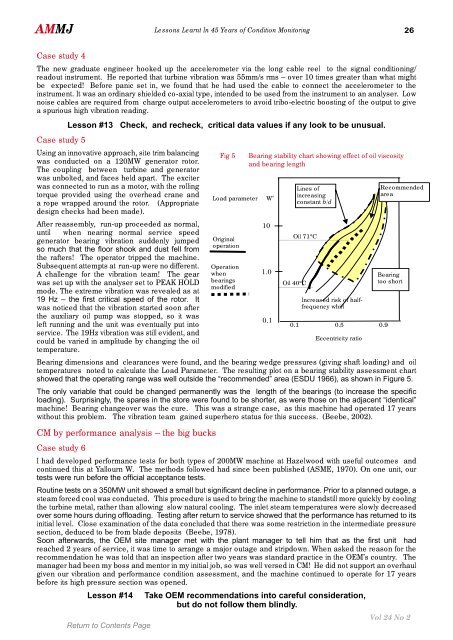
Bearing dimensions and clearances were found, and the bearing wedge pressures (giving shaft loading) and oil<br />
temperatures noted to calculate the Load Parameter. The resulting plot on a bearing stability assessment chart<br />
showed that the operating range was well outside the “recommended” area (ESDU 1966), as shown in Figure 5.<br />
The only variable that could be changed permanently was the length of the bearings (to increase the specific<br />
loading). Surprisingly, the spares in the store were found to be shorter, as were those on the adjacent “identical”<br />
machine! Bearing changeover was the cure. This was a strange case, as this machine had operated 17 years<br />
without this problem. The vibration team gained superhero status for this success. (Beebe, 2002).<br />
CM by performance analysis – the big bucks<br />
Case study 6<br />
Fig 5 Bearing stability chart showing effect of oil viscosity<br />
and bearing length<br />
Load parameter W’<br />
Original<br />
operation<br />
Operation<br />
when<br />
bearings<br />
modified<br />
I had developed performance tests for both types of 200MW machine at Hazelwood with useful outcomes and<br />
continued this at Yallourn W. The methods followed had since been published (ASME, 1970). On one unit, our<br />
tests were run before the official acceptance tests.<br />
Routine tests on a 350MW unit showed a small but significant decline in performance. Prior to a planned outage, a<br />
steam forced cool was conducted. This procedure is used to bring the machine to standstill more quickly by cooling<br />
the turbine metal, rather than allowing slow natural cooling. The inlet steam temperatures were slowly decreased<br />
over some hours during offloading. Testing after return to service showed that the performance has returned to its<br />
initial level. Close examination of the data concluded that there was some restriction in the intermediate pressure<br />
section, deduced to be from blade deposits (Beebe, 1978).<br />
Soon afterwards, the OEM site manager met with the plant manager to tell him that as the first unit had<br />
reached 2 years of service, it was time to arrange a major outage and stripdown. When asked the reason for the<br />
recommendation he was told that an inspection after two years was standard practice in the OEM’s country. The<br />
manager had been my boss and mentor in my initial job, so was well versed in CM! He did not support an overhaul<br />
given our vibration and performance condition assessment, and the machine continued to operate for 17 years<br />
before its high pressure section was opened.<br />
Lesson #14 Take OEM recommendations into careful consideration,<br />
but do not follow them blindly.<br />
10<br />
1.0<br />
0.1<br />
Oil 71°C<br />
Oil 40°C<br />
Lines of<br />
increasing<br />
constant b/d<br />
Increased risk of halffrequency<br />
whirl<br />
0.1 0.5 0.9<br />
Eccentricity ratio<br />
Recommended<br />
area<br />
Bearing<br />
too short<br />
Vol 24 No 2