OWNER'S MANUAL GH-1340W/1440W Lathes - JET Tools
OWNER'S MANUAL GH-1340W/1440W Lathes - JET Tools
OWNER'S MANUAL GH-1340W/1440W Lathes - JET Tools

You also want an ePaper? Increase the reach of your titles
YUMPU automatically turns print PDFs into web optimized ePapers that Google loves.
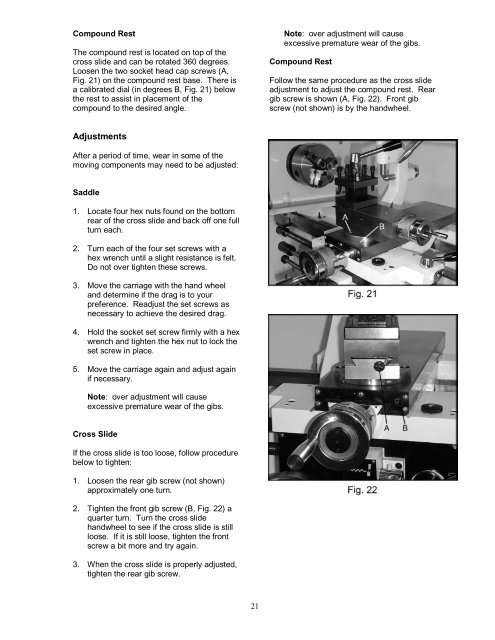
Compound Rest<br />
The compound rest is located on top of the<br />
cross slide and can be rotated 360 degrees.<br />
Loosen the two socket head cap screws (A,<br />
Fig. 21) on the compound rest base. There is<br />
a calibrated dial (in degrees B, Fig. 21) below<br />
the rest to assist in placement of the<br />
compound to the desired angle.<br />
Adjustments<br />
After a period of time, wear in some of the<br />
moving components may need to be adjusted:<br />
Saddle<br />
1. Locate four hex nuts found on the bottom<br />
rear of the cross slide and back off one full<br />
turn each.<br />
2. Turn each of the four set screws with a<br />
hex wrench until a slight resistance is felt.<br />
Do not over tighten these screws.<br />
3. Move the carriage with the hand wheel<br />
and determine if the drag is to your<br />
preference. Readjust the set screws as<br />
necessary to achieve the desired drag.<br />
4. Hold the socket set screw firmly with a hex<br />
wrench and tighten the hex nut to lock the<br />
set screw in place.<br />
5. Move the carriage again and adjust again<br />
if necessary.<br />
Note: over adjustment will cause<br />
excessive premature wear of the gibs.<br />
Cross Slide<br />
If the cross slide is too loose, follow procedure<br />
below to tighten:<br />
1. Loosen the rear gib screw (not shown)<br />
approximately one turn.<br />
2. Tighten the front gib screw (B, Fig. 22) a<br />
quarter turn. Turn the cross slide<br />
handwheel to see if the cross slide is still<br />
loose. If it is still loose, tighten the front<br />
screw a bit more and try again.<br />
3. When the cross slide is properly adjusted,<br />
tighten the rear gib screw.<br />
21<br />
Note: over adjustment will cause<br />
excessive premature wear of the gibs.<br />
Compound Rest<br />
Follow the same procedure as the cross slide<br />
adjustment to adjust the compound rest. Rear<br />
gib screw is shown (A, Fig. 22). Front gib<br />
screw (not shown) is by the handwheel.