Service Bulletin
Service Bulletin
Service Bulletin

Create successful ePaper yourself
Turn your PDF publications into a flip-book with our unique Google optimized e-Paper software.
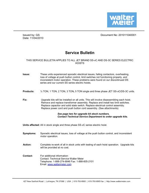
Issued by: GS Document No: 201011040001<br />
Date: 11/04/2010<br />
<strong>Service</strong> <strong>Bulletin</strong><br />
THIS SERVICE BULLETIN APPLIES TO ALL JET BRAND SS-xC AND DS-3C SERIES ELECTRIC<br />
HOISTS<br />
Issue: These units experienced sporadic electrical issues, failing contactors, overheating,<br />
loss of voltage at push button control, limit switches not functioning properly, and<br />
inconsistent motor operation. These problems were found on our discontinued DS<br />
series and our current SS series electric hoists.<br />
Products: ½ TON, 1 TON, 2 TON, 3 TON, 5 TON single and three phase JET SS-xC/DS-3C units.<br />
Fix: Upgrade kits will be installed on all units. This will involve disassembling each hoist.<br />
Remove and replace transformer assembly. Replace and install two limit switches.<br />
Replace capacitor and solid state switch. Replace electrical control assembly.<br />
Replace power cord and push button cord assembly. (See attachments)<br />
See page two for upgrade kit stock numbers.<br />
Contact Technical <strong>Service</strong> Department to order upgrade kits.<br />
Units affected: All in stock single and three phase SS-xC series electric hoist.<br />
Symptoms: Sporadic electrical issues, loss of voltage at the push button control, and inconsistent<br />
motor operation.<br />
Action: Complete re-work of all in stock units with testing of each hoist operation. Upgrade kits<br />
will be provided at no cost.<br />
Contact: For additional information:<br />
Contact: Technical <strong>Service</strong> Walter Meier<br />
Telephone: 1-888-274-6846 Fax: 1-888-605-2101<br />
Email: www.waltermeier.com<br />
427 New Sanford Road | LaVergne, TN 37086 | USA | 615-793-8900 | 615-793-8905 fax | http://www.waltermeier.com
Capacity Phase<br />
Upgrade Kit Stock<br />
Ft. of Lift<br />
Number<br />
Single Speed, 1Ph Electric Hoists<br />
1/2 1 10 1/2SS-1C-UG10<br />
1/2 1 15 1/2SS-1C-UG15<br />
1/2 1 20 1/2SS-1C-UG20<br />
1 1 10 1SS-1C-UG10<br />
1 1 15 1SS-1C-UG15<br />
1 1 20 1SS-1C-UG20<br />
2 1 10 1SS-1C-UG10<br />
2 1 15 1SS-1C-UG15<br />
2 1 20 1SS-1C-UG20<br />
3 1 10 1SS-1C-UG10<br />
3 1 15 1SS-1C-UG15<br />
3 1 20 1SS-1C-UG20<br />
5 1 10 1SS-1C-UG10<br />
5 1 15 1SS-1C-UG15<br />
5 1 20 1SS-1C-UG20<br />
Single Speed, 3Ph Electric Hoists<br />
1/2 3 10 1/2SS-3C-UG10<br />
1/2 3 15 1/2SS-3C-UG15<br />
1/2 3 20 1/2SS-3C-UG20<br />
1 3 10 1SS-3C-UG10<br />
1 3 15 1SS-3C-UG15<br />
1 3 20 1SS-3C-UG20<br />
2 3 10 1SS-3C-UG10<br />
2 3 15 1SS-3C-UG15<br />
2 3 20 1SS-3C-UG20<br />
3 3 10 1SS-3C-UG10<br />
3 3 15 1SS-3C-UG15<br />
3 3 20 1SS-3C-UG20<br />
5 3 10 1SS-3C-UG10<br />
5 3 15 1SS-3C-UG15<br />
5 3 20 1SS-3C-UG20<br />
Dual Speed, 3Ph Electric Hoists<br />
1/2 3 10 1/2DS-3C-UG10<br />
1/2 3 20 1/2DS-3C-UG20<br />
1 3 10 1DS-3C-UG10<br />
1 3 20 1DS-3C-UG20<br />
2 3 10 1DS-3C-UG10<br />
2 3 20 1DS-3C-UG20<br />
3 3 10 1DS-3C-UG10<br />
3 3 20 1DS-3C-UG20<br />
5 3 10 1DS-3C-UG10<br />
5 3 20 1DS-3C-UG20<br />
2<br />
-- Page 2 of 38 ---
Installation process for upgrade kit<br />
For 1 Phase Electric Hoist (1/2 Ton—5Ton)<br />
1. Confirm that the electric hoist is disconnected from the power supply.<br />
2. Unscrew the 8 Phillips pan head machine screws M6×10 (1/2SS-3C-042) from the<br />
motor side cover (1/2SS-3C-102 or 1SS-3C-102).<br />
motor side cover (1/2SS-3C-102<br />
or 1SS-3C-102 )<br />
Figure 1 Figure 2<br />
3. Move the motor side cover (1/2SS-3C-102 or 1SS-3C-102) away from the hoist body.<br />
motor side cover (1/2SS-3C-102<br />
or 1SS-3C-102 )<br />
Phillips pan head machine screw<br />
M6×10 (1/2SS-3C-042)<br />
Figure 3 Figure 4<br />
3<br />
-- Page 3 of 38 ---
-- Page 4 of 38 ---<br />
4. Unscrew the 8 Phillips pan head machine screws M6×10 (1/2SS-3C-042) from the gear<br />
side cover (1/2SS-3C-043 or 1SS-3C-043).<br />
Figure 5<br />
5. Move the gear side cover (1/2SS-3C-043 or 1SS-3C-043) away from the hoist body.<br />
Figure 6<br />
6. Cut the cable ties that tightened wires on the gear side.<br />
Figure 7 cable ties<br />
Figure 8<br />
4<br />
Phillips pan head<br />
machine screws M6×10<br />
(1/2SS-3C-042)<br />
gear side cover<br />
(1/2SS-3C-043 or<br />
1SS-3C-043)<br />
gear side cover<br />
(1/2SS-3C-043<br />
or 1SS-3C-043)
7. Unscrew the screws on the transformer and pull the wires out of the terminals<br />
on the transformer, including the two grounding wires.<br />
Figure 9 Figure 10<br />
grounding wire<br />
Figure 11 Figure 12<br />
8. Disconnect the two bullet quick connectors that connected the brake wires.<br />
Figure 13 Figure 14<br />
bullet quick<br />
connectors<br />
5<br />
-- Page 5 of 38 ---
9. Unscrew the 2 Phillips pan head machine screws M6×10 (1/2SS-3C-042) from the<br />
transformer bracket (1/2SS-3C-050). Remove the transformer.<br />
Figure 15<br />
Phillips pan head<br />
machine screws M6×10 Figure 16<br />
(1/2SS-3C-042)<br />
10. Pull the push-lock terminals with wire out of the two limit switches .<br />
Figure 17 Figure 18<br />
push-lock<br />
terminal<br />
11. Unscrew the 4 Phillips pan head machine screws M3×20 from the two limit switches<br />
(1/2SS-3C-069); remove the switches.<br />
push-lock<br />
Figure 19 terminal<br />
Figure 20<br />
6<br />
limit<br />
switch<br />
terminal<br />
-- Page 6 of 38 ---
12. Cut the cable ties that tightened wires on the motor side.<br />
Figure 21<br />
13. According to the wiring diagram on page 14, disconnect the connections between the<br />
motor wires and the control board.<br />
Motor wires<br />
cable ties<br />
Figure 22<br />
14. Unscrew the Phillips pan head machine screw M8×16 from the motor side plate<br />
(1/2SS-3C-016 or 1SS-3C-016).<br />
Figure 23<br />
7<br />
the control<br />
board<br />
Phillips pan head<br />
machine screws<br />
M8×16<br />
-- Page 7 of 38 ---
15. Pull the wires through the hoist body and back to the motor side.<br />
Wires<br />
were<br />
pulled<br />
Figure 24<br />
16. Unscrew the 2 Phillips pan head machine screws M6×10 (1/2SS-3C-042) from the<br />
motor side plate (1/2SS-3C-016 or 1SS-3C-016 ).<br />
screws M6×10 (1/2SS-3C-042)<br />
Figure 25<br />
17. Remove the control board away from the hoist body. This control board can be<br />
discarded.<br />
control board<br />
Figure 26<br />
8<br />
-- Page 8 of 38 ---
18. Unscrew the four screws on the solid state switch and remove the four red wires.<br />
Figure 27 four red wires Figure 28<br />
19. Unscrew the two Phillips pan head machine screws M4×35 from the electric<br />
component board (for 1 phase) and remove the solid state switch.<br />
the solid state<br />
two Phillips<br />
switch<br />
pan head<br />
Figure 29 machine<br />
Figure 30<br />
screws M4×35<br />
20. Unscrew the Phillips pan head machine screws M4×6 from the electric component<br />
board (for 1 phase) and remove the capacitor.<br />
Phillips pan head<br />
Figure 31 machine screws<br />
Figure 32<br />
M4×6<br />
9<br />
capacitor<br />
holder<br />
capacitor<br />
-- Page 9 of 38 ---
22. Put the new transformer assembly on gear case (1/2SS-3C-037 or 1SS-3C-037) beside<br />
the brake (1/2SS-1C-041 or 1SS-1C-041), then tighten the two Phillips pan head machine<br />
screws M6×10 (1/2SS-3C-042).<br />
New transformer<br />
assembly<br />
gear<br />
Figure 33 Figure 34<br />
brake<br />
23. Install the two new limit switches in position.<br />
New limit<br />
switch<br />
Figure 35<br />
24. Replace capacitor and solid state switch, which was removed earlier, back into<br />
position on the new electric control assembly and tighten screws.<br />
capacitor<br />
Figure 36<br />
10<br />
Solid<br />
state<br />
switch<br />
-- Page 10 of 38 ---
25. Place the new electric control assembly into the correct position by the motor and<br />
orient it properly.<br />
Figure 37<br />
26. According to the new wiring diagram on page 14, reconnect all the wires. Re-attach<br />
cable ties where needed.<br />
Figure 38<br />
11<br />
New electric<br />
control assembly<br />
-- Page 11 of 38 ---
27. Before positioning the new motor side cover, put the new quick connector board<br />
(with two male quick connectors) through the hole.<br />
New motor<br />
side cover<br />
Hole in the<br />
motor side<br />
cover<br />
Figure 39<br />
28.Tighten the 8 Phillips pan head machine screws M6×10 (1/2SS-3C-042).<br />
Figure 40<br />
29. Place the new quick connector board on the motor side cover. Make sure to orient it<br />
properly with the 4P male connector on the left. Tighten the 6 Phillips pan head machine<br />
screws M5×10.<br />
Phillips pan head<br />
machine screws<br />
M5×10<br />
Figure 41<br />
12<br />
New quick connector board<br />
(with two male quick<br />
connectors)<br />
Phillips pan head<br />
machine screws<br />
M6×10<br />
-- Page 12 of 38 ---
-- Page 13 of 38 ---<br />
30. Place the gear side cover into the right position. Tighten the 8 Phillips pan head<br />
machine screws M6×10 (1/2SS-3C-042).<br />
8 Phillips pan head<br />
machine screws<br />
M6×10 (1/2SS-3C-042)<br />
Figure 42<br />
31. Plug the new power cord assembly correctly into the 4P male connector on the left,<br />
then plug the push button cord assembly into the other connector.<br />
New power<br />
cord<br />
assembly<br />
Figure 43<br />
32. Remove the push button switch from the old control pendant assembly (1/2SS-3C-<br />
104), and install it to the new push button cord assembly. Then, according to the Figure<br />
44, connect the wires of the new push button cord assembly.<br />
Wire No.6<br />
Wire No.4<br />
33. The upgrade is complete.<br />
Figure 44<br />
13<br />
gear side<br />
cover<br />
New push<br />
button cord<br />
assembly<br />
Push<br />
button<br />
switch<br />
Wire No.5
New Wiring Diagram: Single Phase Only<br />
14<br />
-- Page 14 of 38 ---
Installation process for upgrade kit<br />
For 3 Phase 1 Speed Electric Hoist (1/2 Ton—5Ton)<br />
1. Confirm that the electric hoist is disconnected from the power supply.<br />
2. Unscrew the 8 Phillips pan head machine screws M6×10 (1/2SS-3C-042) from the<br />
motor side cover (1/2SS-3C-102 or 1SS-3C-102).<br />
motor side cover (1/2SS-3C-<br />
102 or 1SS-3C-102 )<br />
Figure 1 Figure 2<br />
3. Move the motor side cover (1/2SS-3C-102 or 1SS-3C-102) away from the hoist body.<br />
motor side cover (1/2SS-3C-<br />
102 or 1/2SS-3C-102 )<br />
Phillips pan head machine screw<br />
M6×10 (1/2SS-3C-042)<br />
Figure 3 Figure 4<br />
15<br />
-- Page 15 of 38 ---
-- Page 16 of 38 ---<br />
4. Unscrew the 8 Phillips pan head machine screws M6×10 (1/2SS-3C-042) from the gear<br />
side cover (1/2SS-3C-043 or 1SS-3C-043).<br />
Figure 5<br />
5. Move the gear side cover(1/2SS-3C-043 or 1SS-3C-043) away from the hoist body.<br />
Figure 6<br />
6. Cut the cable ties that tightened wires on the gear side.<br />
Figure 7<br />
cable ties<br />
Figure 8<br />
16<br />
Phillips pan head<br />
machine screws<br />
M6×10(1/2SS-3C-042)<br />
gear side cover<br />
(1/2SS-3C-043 or<br />
1SS-3C-043).<br />
gear side cover<br />
(1/2SS-3C-102 or<br />
1SS-3C-043).
7. Unscrew the screws on the transformer and pull the wires out of the terminals on the<br />
transformer, including the two grounding wires.<br />
Figure 9 Figure 10<br />
grounding wire<br />
Figure 11 Figure 12<br />
8. Disconnect the two bullet quick connectors that connected the brake wires.<br />
Figure 13 Figure 14<br />
bullet quick<br />
connectors<br />
17<br />
-- Page 17 of 38 ---
9. Unscrew the 2 Phillips pan head machine screws M6×10 (1/2SS-3C-042) from the<br />
transformer bracket (1/2SS-3C-050), remove the transformer away.<br />
Phillips pan head<br />
Figure 15 machine screws M6×10 Figure 16<br />
(1/2SS-3C-042)<br />
11. Pull the push-lock terminals with wire out of the two limit switches.<br />
push-lock<br />
Figure 17<br />
terminal<br />
Figure 18<br />
limit<br />
switch<br />
terminal<br />
12. Unscrew the 4 Phillips pan head machine screws M3×20 from the two limit switches<br />
(1/2SS-3C-069); remove the switches.<br />
Figure 19 Figure 20<br />
push-lock<br />
terminal<br />
18<br />
-- Page 18 of 38 ---
13. Cut the cable ties that tightened wires on the motor side.<br />
cable ties<br />
Figure 21<br />
14. According to the wiring diagram on page 26, disconnect the connections between the<br />
motor wires and the control board.<br />
the motor wires<br />
Figure 22<br />
15. Unscrew the Phillips pan head machine screw M8×16 from the motor side plate<br />
(1/2SS-3C-016 or 1SS-3C-016 ).<br />
Figure 23<br />
19<br />
the control<br />
board<br />
Phillips pan head<br />
machine screw<br />
M8×16<br />
-- Page 19 of 38 ---
16. Pull the wires through the hoist body and back to the motor side.<br />
Wires were<br />
pulled<br />
Figure 24<br />
17. Unscrew the 2 Phillips pan head machine screws M6×10 (1/2SS-3C-042) from the<br />
motor side plate (1/2SS-3C-016 or 1SS-3C-016 ).<br />
Figure 25<br />
18. Remove the control board away from the hoist body. The control board can be<br />
discarded.<br />
the control board<br />
Figure 26<br />
20<br />
screws M6×10(1/2SS-3C-042)<br />
-- Page 20 of 38 ---
19. Unscrew the nine screws on the reverse phase inspector and pull the nine wires out.<br />
Reverse<br />
phase<br />
inspector<br />
Figure 27 nine wires<br />
Figure 28<br />
20. Unscrew the Phillips pan head machine screws M3×6 from the electric component<br />
board (for 3 phase) and remove the fender.<br />
the fender<br />
two Phillips<br />
pan head<br />
Figure 29 machine<br />
Figure 30<br />
screws M3×6<br />
21 Remove the reverse phase inspector out of the contactor holder.<br />
Figure 31<br />
21<br />
The reverse<br />
phase inspector<br />
The<br />
contactor<br />
holder<br />
-- Page 21 of 38 ---
-- Page 22 of 38 ---<br />
23. Put the new transformer assembly on gear case (1/2SS-3C-037 or 1SS-3C-037) beside<br />
the brake (1/2SS-1C-041 or 1SS-1C-041), then tighten the two Phillips pan head machine<br />
screws M6×10 (1/2SS-3C-042).<br />
gear<br />
New transformer<br />
assembly<br />
Figure 32<br />
24. Install the two new limit switches in position.<br />
New limit<br />
switch<br />
Figure 33<br />
25. Put the reverse phase inspector and the fender, which was removed from the old<br />
electric component board, back on the contactor holder on the new electric control<br />
assembly, and tighten the screw M3. Then install the nine wires into the reverse phase<br />
inspector.<br />
fender<br />
Figure 34 Figure 35<br />
22<br />
brake<br />
The reverse<br />
phase<br />
inspector
26. Install the new electric control assembly by the motor, making sure it is positioned<br />
correctly.<br />
the new electric<br />
control<br />
assembly<br />
Figure 36 Figure 37<br />
27. According to the new wiring diagram on page 26, reconnect all wires. Re-attach cable<br />
ties where needed.<br />
Figure 38<br />
28. Before placing the motor side cover into the proper position, put the new quick<br />
connect board (with two male quick connectors) through the hole.<br />
the hole in the<br />
motor side<br />
cover<br />
motor side<br />
cover<br />
Figure 39<br />
23<br />
the new quick<br />
connect board (with<br />
two male quick<br />
connectors)<br />
-- Page 23 of 38 ---
29. Tighten the 8 Phillips pan head machine screws M6×10 (1/2SS-3C-042).<br />
Figure 40<br />
30. Correctly place the new quick connect board on the motor side cover, then tighten<br />
the 6 Phillips pan head machine screws M5×10. NOTE: The 4P male connector must be<br />
positioned on the left, as shown.<br />
Phillips pan head<br />
machine screws<br />
M5×10<br />
Figure 41<br />
31. Place the gear side cover into the right position. Tighten the 8 Phillips pan head<br />
machine screws M6×10 (1/2SS-3C-042).<br />
the 8 Phillips pan head<br />
machine screws<br />
M6×10 (1/2SS-3C-042)<br />
Figure 42<br />
24<br />
Phillips pan head<br />
machine screws<br />
M6×10<br />
gear side<br />
cover<br />
-- Page 24 of 38 ---
32. Plug the power cord assembly correctly into the 4P male connector on the left, then<br />
plug in the push button cord assembly.<br />
Figure 43<br />
33. Install the pushbutton assembly. Remove the push button switch from the old control<br />
pendant assembly (1/2SS-3C-104), and install it to the new push button cord assembly.<br />
Then, according to Figure 44, connect the wires of the new push button cord assembly.<br />
Wire No.6<br />
Wire No.4<br />
34. The upgrade is complete.<br />
Figure 44<br />
25<br />
Push<br />
button<br />
switch<br />
Wire No.5<br />
-- Page 25 of 38 ---
New Wiring Diagram: 3-Phase, Single Speed Only<br />
26<br />
-- Page 26 of 38 ---
Installation process for upgrade kit<br />
For 3 Phase 2 Speed Electric Hoist (1/2 Ton—5Ton)<br />
1. Confirm that the electric hoist is disconnected from the power supply.<br />
2. Unscrew the 8 Phillips pan head machine screws M6×10 (1/2SS-3C-042) from the<br />
motor side cover (1/2SS-3C-102 or 1SS-3C-102).<br />
motor side cover (1/2SS-3C-102<br />
or 1SS-3C-102 )<br />
Figure 1 Figure 2<br />
3. Move the motor side cover (1/2SS-3C-102 or 1SS-3C-102) away from the hoist body.<br />
motor side cover (1/2SS-3C-102<br />
or 1/2SS-3C-102 )<br />
Phillips pan head machine screw<br />
M6×10 (1/2SS-3C-042)<br />
Figure 3 Figure 4<br />
27<br />
-- Page 27 of 38 ---
-- Page 28 of 38 ---<br />
4. Unscrew the 8 Phillips pan head machine screws M6×10 (1/2SS-3C-042) from the gear<br />
side cover (1/2SS-3C-043 or 1SS-3C-043).<br />
Figure 5<br />
5. Move the gear side cover (1/2SS-3C-043 or 1SS-3C-043) away from the hoist body.<br />
Figure 6<br />
6. Cut the cable ties that tightened wires on the gear side.<br />
Figure 7 cable ties<br />
Figure 8<br />
28<br />
Phillips pan head<br />
machine screws M6×10<br />
(1/2SS-3C-042)<br />
gear side cover<br />
(1/2SS-3C-043 or<br />
1SS-3C-043).<br />
gear side cover<br />
(1/2SS-3C-102 or<br />
1SS-3C-043).
-- Page 29 of 38 ---<br />
7. Unscrew the screws on the transformer and pull the wires out of the terminals on the<br />
transformer, including the two grounding wires.<br />
Figure 9 Figure 10<br />
grounding wire<br />
Figure 11 Figure 12<br />
8. Disconnect the two bullet quick connectors that connected the brake wires.<br />
Figure 13 bullet quick connectors<br />
Figure 14<br />
29
-- Page 30 of 38 ---<br />
9. Unscrew the 2 Phillips pan head machine screws M6×10 (1/2SS-3C-042) from the<br />
transformer bracket (1/2SS-3C-050); remove the transformer.<br />
Phillips pan head<br />
machine screws M6×10<br />
Figure 15 (1/2SS-3C-042)<br />
Figure 16<br />
11. Pull the push-lock terminals with wire out of the two limit switches .<br />
Figure 17 push-lock<br />
Figure 18<br />
terminal<br />
12. Unscrew the 4 Phillips pan head machine screws M3×20 from the two limit switches<br />
(1/2SS-3C-069); remove the switches.<br />
Figure 19 Figure 20<br />
push-lock terminal<br />
30<br />
limit<br />
switch<br />
terminal
13. Cut the cable ties that tightened wires on the motor side.<br />
cable ties<br />
Figure 21<br />
14. According to the wiring diagram on page 38, disconnect the connections between the<br />
motor wires and the control board.<br />
the motor wires<br />
Figure 22<br />
15. Unscrew the Phillips pan head machine screw M8×16 from the motor side plate<br />
(1/2SS-3C-016 or 1SS-3C-016).<br />
Figure 23<br />
31<br />
the control<br />
board<br />
Phillips pan head<br />
machine screws<br />
M8×16<br />
-- Page 31 of 38 ---
16. Pull the wires through the hoist body and back to the motor side.<br />
Wires were<br />
pulled<br />
Figure 24<br />
17. Unscrew the 2 Phillips pan head machine screws M6×10 (1/2SS-3C-042) from the<br />
motor side plate (1/2SS-3C-016 or 1SS-3C-016).<br />
Figure 25<br />
18. Remove the control board away from the hoist body. The control board can be<br />
discarded.<br />
the control board<br />
Figure 26<br />
32<br />
screws M6×10 (1/2SS-3C-042)<br />
-- Page 32 of 38 ---
19. Unscrew the nine screws on the reverse phase inspector and pull the nine wires out.<br />
Reverse<br />
phase<br />
inspector<br />
Figure 27 nine wires<br />
Figure 28<br />
20. Unscrew the Phillips pan head machine screws M3×6 from the electric component<br />
board (for 3 phase) and remove the fender.<br />
two Phillips pan head<br />
machine screws M3×6<br />
the fender<br />
Figure 29 Figure 30<br />
21 Remove the reverse phase inspector from the contactor holder.<br />
Figure31<br />
33<br />
The reverse<br />
phase inspector<br />
The<br />
contactor<br />
holder<br />
-- Page 33 of 38 ---
23. Put the new transformer assembly on gear case (1/2SS-3C-037 or 1SS-3C-037) beside<br />
the brake (1/2SS-1C-041 or 1SS-1C-041), then tighten the two Phillips pan head machine<br />
screws M6×10 (1/2SS-3C-042).<br />
gear<br />
New transformer<br />
assembly<br />
Figure 32<br />
24. Install the two new limit switches in position.<br />
New limit<br />
switch<br />
Figure 33<br />
25. Put the reverse phase inspector and the fender, which was removed earlier, back into<br />
position on the new electric control assembly, and tighten the screw M3. Then install the<br />
nine wires into the reverse phase inspector.<br />
fender<br />
Figure 34 Figure 35<br />
34<br />
brake<br />
The reverse<br />
phase<br />
inspector<br />
-- Page 34 of 38 ---
26. Install the new electric control assembly by the motor, making sure it is positioned<br />
correctly.<br />
Figure 36 Figure 37<br />
27. According to the new wiring diagram on page 38, reconnect all wires. Reattach cable<br />
ties where needed.<br />
Figure 38<br />
35<br />
-- Page 35 of 38 ---<br />
28. Before placing the motor side cover into the right position, put the new quick connect<br />
board (with two male quick connectors) through the hole.<br />
the hole in the<br />
motor side<br />
cover<br />
motor side<br />
cover<br />
the new electric<br />
control<br />
assembly<br />
Figure 39<br />
the new quick connect<br />
board (with two male<br />
quick connectors)
29. Tighten the 8 Phillips pan head machine screws M6×10 (1/2SS-3C-042).<br />
Figure 40<br />
30. Correctly place the new quick connect board on the motor side cover, and tighten the<br />
6 Phillips pan head machine screws M5×10. NOTE: The 4P male connector must be<br />
positioned on the left, as shown.<br />
Phillips pan head<br />
machine screws<br />
M5×10<br />
Figure 41<br />
31. Place the gear side cover into the right position. Tighten the 8 Phillips pan head<br />
machine screws M6×10 (1/2SS-3C-042).<br />
the 8 Phillips pan head<br />
machine screws<br />
M6×10 (1/2SS-3C-042)<br />
Figure 42<br />
36<br />
Phillips pan head<br />
machine screws<br />
M6×10<br />
gear side<br />
cover<br />
-- Page 36 of 38 ---
32. Plug the power cord assembly correctly into the 4P male connect on the left, then<br />
plug in the push button cord assembly.<br />
Figure 43<br />
33. Install the pushbutton assembly. Remove the push button switch from the old control<br />
pendant assembly (1/2SS-3C-104), and install it to the new push button cord assembly.<br />
Then, according to Figure 44, connect the wires of the new push button cord assembly.<br />
Push button<br />
switch<br />
Wire No.4<br />
34. The upgrade is complete.<br />
Figure 44<br />
37<br />
Wire No.6<br />
Wire No.7<br />
Wire No.5<br />
-- Page 37 of 38 ---
New Wiring Diagram: 3-Phase, Dual Speed Only<br />
38<br />
-- Page 38 of 38 ---