Service Bulletin
Service Bulletin
Service Bulletin

Create successful ePaper yourself
Turn your PDF publications into a flip-book with our unique Google optimized e-Paper software.
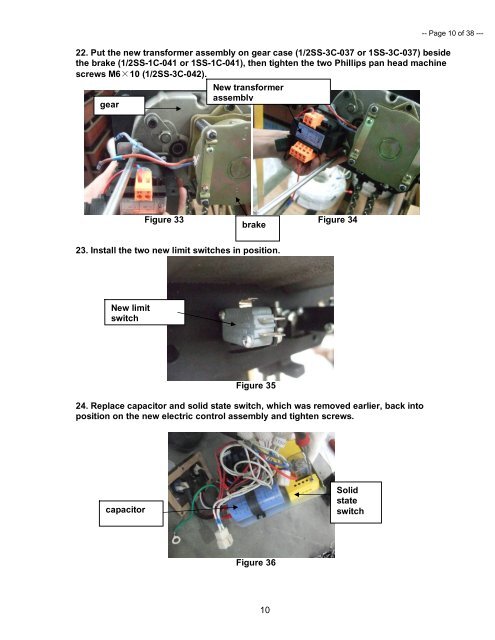
22. Put the new transformer assembly on gear case (1/2SS-3C-037 or 1SS-3C-037) beside<br />
the brake (1/2SS-1C-041 or 1SS-1C-041), then tighten the two Phillips pan head machine<br />
screws M6×10 (1/2SS-3C-042).<br />
New transformer<br />
assembly<br />
gear<br />
Figure 33 Figure 34<br />
brake<br />
23. Install the two new limit switches in position.<br />
New limit<br />
switch<br />
Figure 35<br />
24. Replace capacitor and solid state switch, which was removed earlier, back into<br />
position on the new electric control assembly and tighten screws.<br />
capacitor<br />
Figure 36<br />
10<br />
Solid<br />
state<br />
switch<br />
-- Page 10 of 38 ---