22-inch Variable Speed Drill Press - JET Tools
22-inch Variable Speed Drill Press - JET Tools
22-inch Variable Speed Drill Press - JET Tools
Create successful ePaper yourself
Turn your PDF publications into a flip-book with our unique Google optimized e-Paper software.
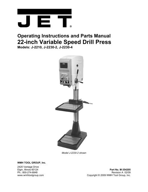
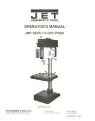
Operating Instructions and Parts Manual<br />
<strong>22</strong>-<strong>inch</strong> <strong>Variable</strong> <strong>Speed</strong> <strong>Drill</strong> <strong>Press</strong><br />
Models: J-<strong>22</strong>10, J-<strong>22</strong>30-2, J-<strong>22</strong>30-4<br />
WMH TOOL GROUP, Inc.<br />
Model J-<strong>22</strong>30-2 shown<br />
2420 Vantage Drive<br />
Elgin, Illinois 60124 Part No. M-354205<br />
Ph.: 800-274-6848 Revision A 02/09<br />
www.wmhtoolgroup.com Copyright © 2009 WMH Tool Group, Inc.
Warranty and Service<br />
WMH Tool Group, Inc., warrants every product it sells. If one of our tools needs service or repair, one of our<br />
Authorized Service Centers located throughout the United States can give you quick service. In most cases, any of<br />
these WMH Tool Group Authorized Service Centers can authorize warranty repair, assist you in obtaining parts, or<br />
perform routine maintenance and major repair on your <strong>JET</strong>® tools. For the name of an Authorized Service Center in<br />
your area call 1-800-274-6848.<br />
MORE INFORMATION<br />
WMH Tool Group is consistently adding new products to the line. For complete, up-to-date product information, check<br />
with your local WMH Tool Group distributor, or visit jettools.com.<br />
WARRANTY<br />
<strong>JET</strong> products carry a limited warranty which varies in duration based upon the product (MW stands for Metalworking,<br />
WW stands for Woodworking).<br />
WHAT IS COVERED?<br />
This warranty covers any defects in workmanship or materials subject to the exceptions stated below. Cutting tools,<br />
abrasives and other consumables are excluded from warranty coverage.<br />
WHO IS COVERED?<br />
This warranty covers only the initial purchaser of the product.<br />
WHAT IS THE PERIOD OF COVERAGE?<br />
The general <strong>JET</strong> warranty lasts for the time period specified in the product literature of each product.<br />
WHAT IS NOT COVERED?<br />
Five Year and Lifetime Warranties do not cover products used for commercial, industrial or educational purposes.<br />
Products with Five Year or Lifetime Warranties that are used for commercial, industrial or education purposes revert<br />
to a One Year Warranty. This warranty does not cover defects due directly or indirectly to misuse, abuse, negligence<br />
or accidents, normal wear-and-tear, improper repair or alterations, or lack of maintenance.<br />
HOW TO GET SERVICE<br />
The product or par t must be returned for examination, postage prepaid, to a location designated by us. For the name<br />
of the location nearest you, please call 1-800-274-6848.<br />
You must provide proof of initial purchase date and an explanation of the complaint must accompany the<br />
merchandise. If our inspection discloses a defect, we will repair or replace the product, or refund the purchase price,<br />
at our option. We will return the repaired product or replacement at our expense unless it is determined by us that<br />
there is no defect, or that the defect resulted from causes not within the scope of our warranty in which case we will,<br />
at your direction, dispose of or return the product. In the event you choose to have the product returned, you will be<br />
responsible for the shipping and handling costs of the return.<br />
HOW STATE LAW APPLIES<br />
This warranty gives you specific legal rights; you may also have other rights which vary from state to state.<br />
LIMITATIONS ON THIS WARRANTY<br />
WMH TOOL GROUP LIMITS ALL IMPLIED WARRANTIES TO THE PERIOD OF THE LIMITED WARRANTY FOR<br />
EACH PRODUCT. EXCEPT AS STATED HEREIN, ANY IMPLIED WARRANTIES OR MERCHANTABILITY AND<br />
FITNESS ARE EXCLUDED. SOME STATES DO NOT ALLOW LIMITATIONS ON HOW LONG THE IMPLIED<br />
WARRANTY LASTS, SO THE ABOVE LIMITATION MAY NOT APPLY TO YOU.<br />
WMH TOOL GROUP SHALL IN NO EVENT BE LIABLE FOR DEATH, INJURIES TO PERSONS OR PROPERTY,<br />
OR FOR INCIDENTAL, CONTINGENT, SPECIAL, OR CONSEQUENTIAL DAMAGES ARISING FROM THE USE<br />
OF OUR PRODUCTS. SOME STATES DO NOT ALLOW THE EXCLUSION OR LIMITATION OF INCIDENTAL OR<br />
CONSEQUENTIAL DAMAGES, SO THE ABOVE LIMITATION OR EXCLUSION MAY NOT APPLY TO YOU.<br />
WMH Tool Group sells through distributors only. The specifications in WMH catalogs are given as general information<br />
and are not binding. Members of WMH Tool Group reserve the right to effect at any time, without prior notice, those<br />
alterations to parts, fittings, and accessory equipment which they may deem necessary for any reason whatsoever.<br />
<strong>JET</strong>® branded products are not sold in Canada by WMH Tool Group.<br />
2
Table of Contents<br />
Table of Contents..........................................................................................................................................3<br />
Warning.........................................................................................................................................................4<br />
Introduction ...................................................................................................................................................6<br />
Specifications ................................................................................................................................................6<br />
Features and Terminology ............................................................................................................................7<br />
Unpacking and Setup....................................................................................................................................8<br />
Contents of the Shipping Container ..........................................................................................................8<br />
Handle Assembly.......................................................................................................................................8<br />
Electrical Connections...............................................................................................................................8<br />
Extension Cords ........................................................................................................................................9<br />
Operating Controls ........................................................................................................................................9<br />
Adjustments ................................................................................................................................................10<br />
Work Table ..............................................................................................................................................10<br />
Arbor/Chuck Removal .............................................................................................................................10<br />
Belt Position (<strong>Speed</strong> Adjustment)............................................................................................................11<br />
Operation.....................................................................................................................................................11<br />
Drive Belt Replacement...........................................................................................................................12<br />
<strong>Drill</strong>ing Recommendations ..........................................................................................................................13<br />
<strong>Speed</strong>s for <strong>Drill</strong>ing ...................................................................................................................................13<br />
Feeds for <strong>Drill</strong>ing .....................................................................................................................................13<br />
Indication of Extreme <strong>Speed</strong>s/Feeds ......................................................................................................13<br />
Troubleshooting ..........................................................................................................................................14<br />
Replacement Parts......................................................................................................................................15<br />
Exploded View: Headstock Assembly.....................................................................................................15<br />
Parts List: Headstock Assembly..............................................................................................................16<br />
Exploded View: Headstock Cover Assembly ..........................................................................................18<br />
Parts List: Headstock Cover Assembly ...................................................................................................19<br />
Exploded View: Base and Column Assembly .........................................................................................20<br />
Parts List: Base and Column Assembly ..................................................................................................21<br />
Electrical Connections – 1 Phase, 230V.....................................................................................................<strong>22</strong><br />
Electrical Connections – 3 Phase, 230V.....................................................................................................23<br />
Electrical Connections – 3 Phase, 460V.....................................................................................................24<br />
3
Warning<br />
1. Read and understand the entire owners manual before attempting assembly or operation.<br />
2. Read and understand the warnings posted on the machine and in this manual. Failure to comply with<br />
all of these warnings may cause serious injury.<br />
3. Replace warning labels if they become obscured or removed.<br />
4. This drill press is designed and intended for use by properly trained and experienced personnel only.<br />
If you are not familiar with the proper and safe operation of a drill press, do not use until proper<br />
training and knowledge have been obtained.<br />
5. Do not use this drill press for other than its intended use. If used for other purposes, WMH Tool<br />
Group disclaims any real or implied warranty and holds itself harmless from any injury that may result<br />
from that use.<br />
6. Always wear approved safety glasses with side shields while using this drill press. (Everyday<br />
eyeglasses only have impact resistant lenses; they are not safety glasses.)<br />
7. Before operating this drill press, remove tie, rings, watches and other jewelry, and roll sleeves up past<br />
the elbows. Remove all loose clothing and confine long hair. Non-slip footwear and safety shoes are<br />
recommended, as well as anti-skid floor strips.<br />
8. Wear ear protectors (plugs or muffs) during extended periods of operation.<br />
9. Some dust created by power sanding, sawing, grinding, drilling and other construction activities<br />
contains chemicals known to cause cancer, birth defects or other reproductive harm. Some examples<br />
of these chemicals are:<br />
• Lead from lead based paint.<br />
• Crystalline silica from bricks, cement and other masonry products.<br />
• Arsenic and chromium from chemically treated lumber.<br />
Your risk of exposure varies, depending on how often you do this type of work. To reduce your<br />
exposure to these chemicals, work in a well-ventilated area and work with approved safety<br />
equipment, such as face or dust masks that are specifically designed to filter out microscopic<br />
particles.<br />
10. Do not operate this machine while tired or under the influence of drugs, alcohol or any medication.<br />
11. Make certain the switch is in the OFF position before connecting the machine to the power supply.<br />
12. Make certain the machine is properly grounded.<br />
13. Make all machine adjustments or maintenance with the machine unplugged from the power source.<br />
14. Remove adjusting keys and wrenches. Form a habit of checking to see that keys and adjusting<br />
wrenches are removed from the machine before turning it on.<br />
15. All work must be secured using either clamps or a vise to the drill press table. It is unsafe to use your<br />
hands to hold any workpiece being drilled.<br />
16. Keep hands in sight; do not put hands or fingers around, on, or below any rotating cutting tools.<br />
Leather safety gloves should be used when handling any sharp objects or cutting tools.<br />
17. <strong>Drill</strong> press head and table shall be securely locked to the column before operating the machine. Make<br />
a habit of checking this before each operating session.<br />
18. Avoid contact with coolant, especially the eyes and face area.<br />
19. Keep safety guards in place at all times when the machine is in use. If removed for maintenance<br />
purposes, use extreme caution and replace the guards immediately after maintenance is complete.<br />
20. Make sure the drill press is firmly anchored to the floor before use.<br />
4
21. Check damaged parts. Before further use of the machine, a guard or other part that is damaged<br />
should be carefully checked to determine that it will operate properly and perform its intended<br />
function. Check for alignment of moving parts, binding of moving parts, breakage of parts, mounting<br />
and any other conditions that may affect its operation. A guard or other part that is damaged should<br />
be properly repaired or replaced.<br />
<strong>22</strong>. Provide for adequate space surrounding work area and non-glare, overhead lighting.<br />
23. Keep the floor around the machine clean and free of scrap material, oil and grease.<br />
24. Keep visitors a safe distance from the work area. Keep children away.<br />
25. Make your workshop child proof with padlocks, master switches or by removing starter keys.<br />
26. Give your work undivided attention. Looking around, carrying on a conversation and “horse-play” are<br />
careless acts that can result in serious injury.<br />
27. Maintain a balanced stance at all times so that you do not fall or lean against the rotating tool or other<br />
moving parts. Do not overreach or use excessive force to perform any machine operation.<br />
28. Always use the correct tooling. Tooling must be maintained and properly sharpened. All tooling must<br />
be run at the proper speeds and feed rates as they apply to the job. Use only recommended<br />
accessories and follow those manufacturer’s instructions pertaining to them. Tooling shall not be<br />
forced into any workpiece but fed according to the proper specifications.<br />
29. Use recommended accessories; improper accessories may be hazardous.<br />
30. Turn off the machine and disconnect from power before cleaning. Use a brush or compressed air to<br />
remove chips or debris — do not use your hands.<br />
31. Do not stand on the machine. Serious injury could occur if the machine tips over.<br />
32. Never leave the machine running unattended. Turn the power off and do not leave the machine until it<br />
comes to a complete stop.<br />
33. Remove loose items and unnecessary work pieces from the area before starting the machine.<br />
34. Failure to follow the above instructions may result in risk of personal injury or damage to the machine.<br />
Familiarize yourself with the following safety notices used in this manual:<br />
This means that if precautions are not heeded, it may result in minor injury and/or<br />
possible machine damage.<br />
even death.<br />
This means that if precautions are not heeded, it may result in serious injury or possibly<br />
5
Introduction<br />
This manual is provided by WMH Tool Group covering the safe operation and maintenance procedures<br />
for the <strong>JET</strong> Model J-<strong>22</strong>10 and J-<strong>22</strong>30 <strong>Drill</strong> <strong>Press</strong>es. This manual contains instructions on installation,<br />
safety precautions, general operating procedures, maintenance instructions and parts breakdown. This<br />
machine has been designed and constructed to provide years of trouble free operation if used in<br />
accordance with instructions set forth in this manual. If there are any questions or comments, please<br />
contact either your local supplier or WMH Tool Group. WMH Tool Group can also be reached at our web<br />
site: www.wmhtoolgroup.com.<br />
Specifications<br />
Model:.....................................................................J-<strong>22</strong>10 ......................... J-<strong>22</strong>30-2 ......................J-<strong>22</strong>30-4<br />
Stock Number .......................................................354205 ............................354206 ........................ 354207<br />
Motor ...................................................... 2HP, 1Ph, 230V ..............2HP, 3Ph, 230V .......... 2HP, 3Ph, 460V<br />
<strong>Drill</strong>ing Capacity (in.)<br />
Cast Iron............................................................1-1/4 ............................... 1-1/4 ............................1-1/4<br />
Steel ..................................................................1-1/8 ............................... 1-1/8 ............................1-1/8<br />
Column Diameter (in.) .............................................4-5/16 ............................. 4-5/16 ..........................4-5/16<br />
Maximum Dimension Spindle to Column (in.)...............11 ....................................11 ................................ 11<br />
Spindle Taper........................................................... MT-3 ............................... MT-3 ............................MT-3<br />
Spindle Travel (in.) ..........................................................5 ......................................5 .................................. 5<br />
Spindle Dimension to Base (in.)..............................46-1/2 ............................. 46-1/2 ..........................46-1/2<br />
Spindle Dimension to Table (in.).............................32-3/4 ............................. 32-3/4 ..........................32-3/4<br />
Table Size (in.) ..........................................16-1/8 x 19-1/4 ............... 16-1/8 x 19-1/4 ............16-1/8 x 19-1/4<br />
Number of T-slots.............................. 2 in table, 2 in base ........ 2 in table, 2 in base .....2 in table, 2 in base<br />
Spindle <strong>Speed</strong> Range (RPM) ............60-450 & 240-1800 ...........60-450 & 120-900 ....... 60-450 & 120-900<br />
....................................................................................N/A .......120-900 & 240-1800 ... 120-900 & 240-1800<br />
Overall Height (in.) ........................................................73 ....................................73 ................................ 73<br />
Base Size (in.)...........................................19-3/8 x 29-1/4 ............... 19-3/8 x 29-1/4 ............19-3/8 x 29-1/4<br />
Table Travel (in.) .....................................................26-1/2 ............................. 26-1/2 ..........................26-1/2<br />
Net Weight – approximate (lbs.) .................................660 ..................................660 .............................. 660<br />
Shipping Weight – approximate (lbs.) .........................790 ..................................790 .............................. 790<br />
The above specifications were current at the time this manual was published, but because of our policy of<br />
continuous improvement, WMH Tool Group reserves the right to change specifications at any time and<br />
without prior notice, without incurring obligations.<br />
6
Features and Terminology<br />
Figure 1<br />
7
Unpacking and Setup<br />
Open shipping container and check for shipping<br />
damage. Report any damage immediately to<br />
your distributor and shipping agent. Do not<br />
discard any shipping material until the <strong>Drill</strong><br />
<strong>Press</strong> is installed and running properly.<br />
Compare the contents of your container with the<br />
following parts list to make sure all parts are<br />
intact. Missing parts, if any, should be reported<br />
to your distributor. Read this manual thoroughly<br />
for installation, maintenance and safety<br />
instructions.<br />
Contents of the Shipping Container<br />
1 <strong>Drill</strong> <strong>Press</strong><br />
1 Drift Key<br />
2 Keys (for lockout switch)<br />
3 Handles<br />
1 Hex (Allen) wrench, 6mm<br />
1 Owner's Manual<br />
1 Warranty Card<br />
Remove all packing material from around the<br />
drill press, remove the four bolts in the base,<br />
and lift the drill press from the pallet using forklift<br />
or hoist.<br />
The drill press should be secured to a concrete<br />
floor for optimum stability. The base of the drill<br />
press has four mounting holes for this purpose.<br />
The drill press should be level and rest solidly<br />
on the floor. Place shims under the base as<br />
needed to level the drill press.<br />
When securing the base to the floor, apply even<br />
torque to the fasteners to prevent distortion of<br />
the base.<br />
Handle Assembly<br />
Insert the three handles into the hub (Figure 2).<br />
Use a wrench on the flats to tighten the handles<br />
to the hub.<br />
Before operating the drill press, give it an overall<br />
inspection to make sure all components are<br />
functioning properly.<br />
Electrical Connections<br />
Electrical connections must<br />
be made by a qualified electrician in<br />
compliance with all relevant codes. The<br />
machine must be properly grounded to help<br />
prevent electrical shock and possible fatal<br />
injury.<br />
8<br />
Figure 2
A power plug is not provided with the drill press.<br />
You may either connect the proper UL/CSA<br />
listed plug, or "hard-wire" the machine directly to<br />
a service panel, provided there is a disconnect<br />
near the machine for the operator. During hardwiring<br />
of the machine, make sure the fuses have<br />
been removed or the breakers have been<br />
tripped in the circuit to which the drill press will<br />
be connected. Place a warning placard on the<br />
fuse holder or circuit breaker to prevent it being<br />
turned on while the machine is being wired.<br />
When the 3-phase model is properly wired, the<br />
spindle turns clockwise in a conventional drilling<br />
rotation. If the spindle rotates the wrong<br />
direction, disconnect the machine from power<br />
and switch any two of the three incoming leads.<br />
Consult the electrical diagrams on pages <strong>22</strong>-24<br />
for further clarification of wiring.<br />
This machine must be grounded. Grounding<br />
provides a path of least resistance to help divert<br />
current away from the operator in case of<br />
electrical malfunction.<br />
Make sure the voltage of your power supply<br />
matches the specifications on the motor plate of<br />
the machine.<br />
Extension Cords<br />
For circuits which are far away from the<br />
electrical service box, the wire size must be<br />
increased in order to deliver ample voltage to<br />
the motor. An undersized cord will cause a drop<br />
in line voltage resulting in loss of power and<br />
overheating.<br />
The chart in Figure 3 shows the recommended<br />
size cord to use for branch circuits and<br />
extension cords. The smaller the gauge number<br />
the heavier the cord. If in doubt, use the next<br />
heavier wire gauge.<br />
Operating Controls<br />
(Figure 4)<br />
The keyed On/Off Switch activates power to<br />
the drill press, and can be locked in the OFF<br />
position to prevent unauthorized use.<br />
The Selector Switch is used to determine<br />
direction of spindle rotation (Fwd/Rev) and to set<br />
the speed range (1 or 2).<br />
The Emergency Stop button is for fast shut<br />
down of drilling operations. Before re-starting<br />
the drill press, rotate the emergency stop button<br />
clockwise until it disengages. NOTE: Use the<br />
basic stop button for normal stoppage of drill<br />
rotation.<br />
9<br />
Recommended Gauges (AWG) of Extension Cords<br />
Amps<br />
25<br />
feet<br />
Extension Cord Length *<br />
50<br />
feet<br />
75<br />
feet<br />
100<br />
feet<br />
150<br />
feet<br />
200<br />
feet<br />
< 5 16 16 16 14 12 12<br />
5 to 8 16 16 14 12 10 NR<br />
8 to 12 14 14 12 10 NR NR<br />
12 to 15 12 12 10 10 NR NR<br />
15 to 20 10 10 10 NR NR NR<br />
21 to 30 10 NR NR NR NR NR<br />
*based on limiting the line voltage drop to 5V at 150% of the<br />
rated amperes.<br />
NR: Not Recommended.<br />
Figure 3<br />
Figure 4
The Depth Indicator (Figure 5) can be set for<br />
drilling depths up to 5”.<br />
1. To set the Depth Indicator, lower the end of<br />
the drill against the surface into which the<br />
hole is to be drilled.<br />
2. Loosen the handle on the pointer, and slide it<br />
to the approximate position on the depth<br />
gauge which matches your hole depth.<br />
3. Tighten the handle, and then use the knurled<br />
wheel to fine-adjust the pointer into position.<br />
4. When drilling the hole, lower the spindle until<br />
the pointer reaches zero.<br />
A <strong>Speed</strong> Setting Handwheel is provided on the<br />
left side of the head. The handwheel is turned<br />
clockwise to increase spindle speed and<br />
counterclockwise to reduce speed. Check the<br />
speed by viewing the LED readout. <strong>Speed</strong> is<br />
also dependent upon the belt and pulley<br />
configuration (see “Belt Position”).<br />
Only turn the speed setting<br />
handwheel while the motor is running,<br />
otherwise damage to the speed adjustment<br />
mechanism may occur.<br />
Adjustments<br />
Work Table<br />
The table can be raised or lowered to<br />
accommodate the height of the workpiece. It<br />
should be raised enough to allow for minimum<br />
spindle movement. To raise or lower the table,<br />
loosen the two locking handles and rotate the<br />
crank handle. Always re-tighten both locking<br />
handles before operating.<br />
The work table can also be rotated on the<br />
column by loosening the two locking handles<br />
and shifting the table (along with the rack). This<br />
is usually done when drilling large workpieces,<br />
with the table shifted out of the way and the<br />
work piece secured by using jigs in the T-slots<br />
on the machine’s base.<br />
Arbor/Chuck Removal<br />
(An arbor and chuck are not included with the<br />
drill press.)<br />
1. Disconnect machine from power source.<br />
2. Lower the spindle and rotate it by hand until<br />
the slots in spindle and quill are aligned<br />
(Figure 6).<br />
3. Insert the drift key through the slot and tap it<br />
in with a wood or rubber mallet until the<br />
arbor/chuck drops out. Hold the arbor/chuck<br />
to prevent it from falling.<br />
10<br />
Figure 5<br />
Figure 6
Be sure to remove drift key<br />
from spindle before starting the drill press.<br />
Belt Position (<strong>Speed</strong> Adjustment)<br />
1. To change the speed range of the drill press,<br />
remove the access door on the side of the<br />
head.<br />
2. Loosen the locking handles and pull the<br />
tension lever to release tension on the belt.<br />
See Figure 7.<br />
NOTE: The handles are adjustable. Simply<br />
pull down on the handle, rotate it on its hub,<br />
then release it, making sure it seats itself<br />
properly on the hub.<br />
3. Move the belt to the other set of pulleys, push<br />
the tension lever back into place and retighten<br />
the locking handles.<br />
4. Close the access door.<br />
Figure 8 shows the speed ranges according to<br />
belt position and the setting of the selection<br />
switch on the front of the drill head.<br />
Operation<br />
The following operating and safety precautions<br />
must be observed in order to avoid harm to the<br />
operator or damage to the drill press.<br />
1. The work table must be locked to the<br />
column so it will not be forced down the<br />
column.<br />
2. Be sure the belt is tightened to the proper<br />
tension.<br />
3. Do not begin drilling until you are certain<br />
that the workpiece is held down securely.<br />
4. Make sure the drive motor is running before<br />
turning the speed setting handwheel in<br />
either direction.<br />
5. Make sure the drill is secured in the spindle<br />
or chuck before attempting to use the drill<br />
press.<br />
6. Make sure the spindle taper is clean and<br />
free of burrs, scoring and galling to ensure<br />
maximum gripping.<br />
11<br />
Figure 7<br />
3 Phase Model<br />
Belt on upper pulleys<br />
Selector Switch at 1: 120-900 RPM<br />
Selector Switch at 2: 240-1800 RPM<br />
Belt on lower pulleys<br />
Selector Switch at 1: 60-450 RPM<br />
Selector Switch at 2: 120-900 RPM<br />
1 Phase Model<br />
Belt on upper pulleys<br />
240-1800 RPM<br />
Belt on lower pulleys<br />
60-450 RPM<br />
Figure 8
Maintenance<br />
Make sure to disconnect<br />
electrical power to the drill press before<br />
performing maintenance, to avoid the<br />
possibility of inadvertent operation and<br />
exposure to potentially lethal voltage levels.<br />
Drive Belt Replacement<br />
1. Remove the pulley access door.<br />
2. Start drill press. Set speed control to highest<br />
speed. Stop drill press.<br />
3. Disconnect electrical power by pulling out<br />
the plug or switching off the circuit.<br />
4. Remove the handwheel and/or the turret<br />
hub, and remove the headstock cover.<br />
5. Release tension from the belt, and remove<br />
belt.<br />
6. Install the replacement belt and tension it.<br />
Tighten both locking handles. Re-install the<br />
pulley access door.<br />
7. Re-connect the drill press to power, and<br />
operate it to verify correct belt movement.<br />
If the power cord is worn, cut, or damaged in<br />
any way, have it replaced immediately.<br />
Following are lubrication recommendations for<br />
drill press components (Figures 9 and 10):<br />
Spindle pulley drive: Lubricate spindle splines<br />
occasionally with light grease.<br />
Quill and column: Lubricate with light film of<br />
SAE-20 oil.<br />
Rack: Lubricate regularly with SAE 20 oil (clean<br />
rack with kerosene before applying oil).<br />
Table raising shaft: Lubricate with oil through<br />
the oil fittings.<br />
12<br />
Figure 9<br />
Figure 10
<strong>Drill</strong>ing Recommendations<br />
<strong>Speed</strong>s for <strong>Drill</strong>ing<br />
The speed of a drill is usually measured in terms<br />
of the rate at which the outer periphery of the<br />
tool moves in relation to the work being drilled.<br />
The common term for this is Surface Feet per<br />
Minute (SFM). The relationship of SFM is<br />
expressed in the following formulas:<br />
SFM=0.26 x RPM x <strong>Drill</strong> Diameter (in <strong>inch</strong>es)<br />
RPM=3.8 x _________SFM_________<br />
<strong>Drill</strong> diameter (in <strong>inch</strong>es)<br />
In general, the higher the speed the shorter the<br />
drill life. Operating at the low end of the speed<br />
range for a particular material will result in<br />
longer life. The most efficient speed for<br />
operating a drill depends on many variables:<br />
1. Composition and hardness of material.<br />
2. Depth of the hole.<br />
3. Efficiency of the cutting fluid.<br />
4. Type and condition of the drilling machine.<br />
5. Desired quality of the hole.<br />
6. Difficulty of set-up.<br />
Feeds for <strong>Drill</strong>ing<br />
The feed of a drill is governed by the size of the<br />
tool and the material drilled. Because the feed<br />
rate partially determines the rate of production<br />
and also is a factor in tool life, it should be<br />
chosen carefully for each job. In general, the<br />
most effective feeds will be found in the ranges<br />
shown in Figure 11.<br />
Indication of Extreme <strong>Speed</strong>s/Feeds<br />
Figure 12 shows recommended speed ranges<br />
for high speed steel drills.<br />
A drill that splits up the web is evidence of too<br />
much feed or insufficient tip clearance at the<br />
center as a result of improper grinding. The<br />
rapid wearing away of the extreme outer corners<br />
of the cutting edges indicates that the speed is<br />
too high. A drill chipping or breaking out at the<br />
cutting edges indicates that either the feed is too<br />
heavy or the drill has been ground with too<br />
much tip clearance.<br />
In cases where carbon steel drills are<br />
applicable, the drill should be run at speeds of<br />
from 40 to 50 percent of those given in Figure<br />
12.<br />
13<br />
Feed Rates per <strong>Drill</strong> Size<br />
Diameter of <strong>Drill</strong><br />
(<strong>inch</strong>es)<br />
Feed per Revolution<br />
(<strong>inch</strong>es)<br />
Under 1/8 0.001 to 0.002<br />
1/8 to 1/4 0.002 to 0.004<br />
1/4 to 1/2 0.004 to 0.007<br />
1/2 to 5/8 0.007 to 0.015<br />
Figure 11<br />
<strong>Speed</strong>s for High <strong>Speed</strong> Steel <strong>Drill</strong>s<br />
Material<br />
<strong>Speed</strong><br />
(SFPM)<br />
Alloy Steel – 300 to 400 Brinell 20-30<br />
Stainless Steel 30-40<br />
Automotive Steel Forgings 40-50<br />
Tool Steel, 1.2C 50-60<br />
Steel, .4C to .5C 70-80<br />
Mild Machinery Steel, .2C to .3C 80-110<br />
Hard Chilled Cast Iron 30-40<br />
Medium Hard Cast Iron 70-100<br />
Soft Cast Iron 100-150<br />
Malleable Iron 80-90<br />
High Nickel Steel or Monel 40-50<br />
High Tensile Bronze 70-150<br />
Ordinary Brass and Bronze 200-300<br />
Aluminum and its Alloys 200-300<br />
Magnesium and its Alloys 250-400<br />
Slate, Marble, and Stone 15-25<br />
Plastics and similar material (Bakelite) 100-150<br />
Wood 300-400<br />
Titanium Alloys 10-25<br />
Titanium Alloy Sheet 50-60<br />
Figure 12
Troubleshooting<br />
Trouble Probable Cause Remedy<br />
Spindle does not turn.<br />
Spindle is noisy.<br />
<strong>Drill</strong> stalls.<br />
Poorly drilled holes.<br />
Motor overheating.<br />
Motor overload protector tripped. <strong>Press</strong> motor overload reset button.<br />
Circuit breaker tripped. Re-set circuit breaker.<br />
Branch circuit breaker tripped or fuse<br />
blown.<br />
14<br />
Re-set branch circuit breaker/replace<br />
fuse.<br />
Open wire in switch circuit. Repair open circuit.<br />
Defective switch. Replace switch.<br />
Broken drive belt. Replace drive belt.<br />
Damaged spindle bearings. Replace bearings.<br />
Worn spline. Replace spline.<br />
Worn drive belt.<br />
Excessive feed rate for size of drill and<br />
material being drilled. No cutting fluid or<br />
improper cutting fluid.<br />
Check condition of belt. Replace if glazed<br />
or slipping on pulleys.<br />
Reduce feed pressure or use cutting fluid.<br />
Use correct cutting fluid.<br />
<strong>Drill</strong> is dull. Sharpen or replace drill.<br />
Lack of rigidity in hold-down method.<br />
<strong>Speed</strong> too fast for material and drill size.<br />
Feed too fast for material and drill size. Reduce feed rate.<br />
No fluid, or improper cutting fluid or<br />
coolant being used.<br />
Improperly ground drill bit.<br />
Electrical circuit fault.<br />
Oversize drill. Reduce drill size.<br />
Excessive feed rate. Reduce feed rate.<br />
No cutting fluid, or incorrect type of fluid.<br />
Check that all T-slot hold-downs are tight<br />
and that table lock and drill head bolts are<br />
tight.<br />
Check spindle speed recommendations.<br />
Reduce speed if necessary.<br />
Use cutting fluid, or change to proper fluid<br />
or coolant for material being drilled.<br />
Check for proper angles and reliefs. Regrind<br />
to proper geometry, or replace.<br />
Check current draw in circuit. Make sure<br />
current draw is the same as rating on<br />
motor plate.<br />
Use correct cutting fluid for the material<br />
and drill.<br />
Table can not be raised. Lack of lubrication. Lubricate. See page 12.<br />
No speed readout. <strong>Speed</strong> pickup out of adjustment or failed.<br />
Adjust gap between speed pickup and<br />
post spindle pulley. If there is no readout<br />
on the LED speed indicator after adjusting<br />
the gap, replace the speed pickup. NOTE:<br />
This adjustment should be made by a<br />
qualified technician.
Replacement Parts<br />
Replacement parts are listed on the following pages. To order parts or reach our service department, call<br />
1-800-274-6848 between 7:30 a.m. and 6:00 p.m. (CST), Monday through Friday. Having the Model<br />
Number and Serial Number of your machine available when you call will allow us to serve you quickly and<br />
accurately.<br />
Exploded View: Headstock Assembly<br />
35 31<br />
36 32<br />
27<br />
26<br />
25<br />
23<br />
16<br />
15<br />
14<br />
13<br />
12<br />
30<br />
29<br />
28<br />
9<br />
34<br />
24<br />
<strong>22</strong> 18<br />
20<br />
107<br />
19A<br />
11<br />
21 18<br />
19 106<br />
10<br />
37<br />
103<br />
104<br />
105<br />
D<br />
9<br />
28<br />
31<br />
B<br />
17<br />
8<br />
66<br />
65<br />
64<br />
62<br />
61<br />
59<br />
48<br />
48<br />
1<br />
C<br />
A<br />
2<br />
3<br />
4<br />
5<br />
6<br />
7<br />
57<br />
67<br />
63<br />
60<br />
58<br />
56<br />
55<br />
46<br />
45<br />
15<br />
21<br />
44<br />
43<br />
42<br />
40<br />
101<br />
79<br />
81<br />
98<br />
97<br />
96<br />
95<br />
94<br />
93<br />
92<br />
94<br />
91<br />
51<br />
52<br />
D<br />
102<br />
100<br />
77<br />
99<br />
90<br />
88<br />
87<br />
58<br />
86<br />
54<br />
53<br />
50<br />
49<br />
48<br />
47<br />
39<br />
89<br />
38<br />
41<br />
4<br />
85<br />
B<br />
84<br />
83<br />
82<br />
81<br />
16<br />
80<br />
79<br />
78<br />
77<br />
76<br />
75<br />
74<br />
73<br />
94<br />
72<br />
71<br />
70<br />
69<br />
68<br />
2
Parts List: Headstock Assembly<br />
Index No. Part No. Description Size Qty<br />
1 ...............<strong>22</strong>10-201..................Headstock ............................................................ .................................... 1<br />
2 ...............<strong>22</strong>10-202..................Strain Relief Connector........................................ PG13.5........................ 3<br />
3 ...............<strong>22</strong>10-203..................Handle Hub .......................................................... .................................... 1<br />
4 ...............TS-1504061 .............Socket Head Cap Screw...................................... M8x30 .........................5<br />
5 ...............<strong>22</strong>10-205..................Pin ........................................................................ Ø8x30 ......................... 1<br />
.................<strong>22</strong>10-206A ...............Handle Assembly (Item #6 & #7) ......................... .................................... 1<br />
6 ...............<strong>22</strong>10-206..................Handle.................................................................. .................................... 3<br />
7 ...............<strong>22</strong>10-207..................Handle Grip.......................................................... .................................... 3<br />
8 ...............<strong>22</strong>10-208..................Feed Shaft............................................................ .................................... 1<br />
9 ...............TS-1524031 .............Set Screw............................................................. M8x12 ......................... 2<br />
10 .............<strong>22</strong>10-210..................Star Washer ......................................................... M4............................... 2<br />
11 .............TS-1532042 .............Pan Head Screw .................................................. M4x12 ......................... 1<br />
.................<strong>22</strong>10-212A ...............Spring Cap Assembly (Item #12 & #13) .............. .................................... 1<br />
12 .............<strong>22</strong>10-212..................Spring................................................................... .................................... 1<br />
13 .............<strong>22</strong>10-213..................Spring Cap ........................................................... .................................... 1<br />
14 .............TS-1533042 .............Pan Head Screw .................................................. M5x12 ......................... 2<br />
15 .............<strong>22</strong>10-215..................Spring Seat Shaft................................................. .................................... 1<br />
16 .............TS-1504121 .............Socket Head Cap Screw...................................... M8x60 ......................... 2<br />
17 .............<strong>22</strong>10-217..................Shaft..................................................................... .................................... 1<br />
18 ............TS-1540071 .............Hex Nut ................................................................ M10............................ 2<br />
19 .............<strong>22</strong>10-219..................Clamp................................................................... .................................... 2<br />
20 .............<strong>22</strong>10-<strong>22</strong>0..................Scale Collar.......................................................... .................................... 1<br />
21 .............<strong>22</strong>10-<strong>22</strong>1..................Drive Screw.......................................................... 2x5 .............................. 6<br />
<strong>22</strong> .............TS-1523021 .............Set Screw............................................................. M6x8 ........................... 1<br />
23 .............<strong>22</strong>10-<strong>22</strong>3..................Hand Wheel ......................................................... .................................... 1<br />
24 .............<strong>22</strong>10-<strong>22</strong>4..................Handle.................................................................. .................................... 3<br />
25 .............<strong>22</strong>10-<strong>22</strong>5..................Key ....................................................................... 5x5x<strong>22</strong> ........................ 1<br />
26 .............TS-1550071 .............Flat Washer.......................................................... M10............................. 1<br />
27 .............TS-<strong>22</strong>10161 .............Hex Cap Screw .................................................... M10x16 ....................... 1<br />
28 .............<strong>22</strong>10-<strong>22</strong>8..................Bushing ................................................................ .................................... 2<br />
29 .............<strong>22</strong>10-<strong>22</strong>9A ...............Bracket................................................................. .................................... 1<br />
30 .............TS-1504041 .............Socket Head Cap Screw...................................... M8x20 ......................... 4<br />
31 .............TS-1551061 .............Lock Washer ........................................................ M8............................... 5<br />
32 .............TS-1540071 .............Hex Nut ................................................................ M10............................. 3<br />
34 .............<strong>22</strong>10-234..................Rack ..................................................................... .................................... 1<br />
35 .............TS-1504081 .............Socket Head Cap Screw...................................... M8x40 ......................... 1<br />
36 .............<strong>22</strong>10-236A ...............Moving Bracket .................................................... .................................... 1<br />
37 .............<strong>22</strong>10-237A ...............Socket Head Cap Screw...................................... M10x100 ..................... 1<br />
38 .............<strong>22</strong>10-238..................Spindle ................................................................. .................................... 1<br />
39 .............TS-1504091 .............Socket Head Cap Screw...................................... M8x45 ......................... 1<br />
40 .............<strong>22</strong>10-240..................Adjustment Nut .................................................... .................................... 1<br />
41 .............<strong>22</strong>10-241..................Seat...................................................................... .................................... 1<br />
42 .............<strong>22</strong>10-242..................Scale Bolt............................................................. .................................... 1<br />
43 .............<strong>22</strong>10-243..................Set Block.............................................................. .................................... 1<br />
44 .............<strong>22</strong>10-244..................Pointer.................................................................. .................................... 1<br />
45 .............<strong>22</strong>10-245..................Locking Handle .................................................... M6x40 ......................... 1<br />
46 .............<strong>22</strong>10-246..................C-Ring.................................................................. STW-20....................... 1<br />
47 .............<strong>22</strong>10-247..................O-Ring.................................................................. P62.............................. 1<br />
48 .............BB-6008ZZ...............Ball Bearing.......................................................... 6008ZZ........................ 3<br />
49 .............<strong>22</strong>10-249..................Quill ...................................................................... .................................... 1<br />
50 .............BB-6006ZZ...............Ball Bearing.......................................................... 6006ZZ........................ 1<br />
51 .............<strong>22</strong>10-251..................Pin ........................................................................ .................................... 2<br />
52 .............TS-1504061 .............Socket Head Cap Screw...................................... M8x30 ......................... 2<br />
53 .............<strong>22</strong>10-253..................Bearing Lock Washer........................................... .................................... 1<br />
54 .............<strong>22</strong>10-254..................Bearing Nut .......................................................... .................................... 1<br />
55 .............<strong>22</strong>10-255..................C-Ring.................................................................. STW-40....................... 1<br />
56 .............TS-1490041 .............Hex Cap Screw .................................................... M8x25 ......................... 2<br />
16
57 .............<strong>22</strong>10-257..................Bearing Housing .................................................. .................................... 1<br />
58 .............TS-1550061 .............Flat Washer.......................................................... M8............................... 3<br />
59 .............<strong>22</strong>10-259..................Driving Sleeve...................................................... .................................... 1<br />
60 .............<strong>22</strong>10-260..................Key ....................................................................... 6x6x40 ........................ 1<br />
61 .............<strong>22</strong>10-261..................Spindle Pulley ...................................................... 1Ph.............................. 1<br />
.................<strong>22</strong>10-261A ...............Spindle Pulley ...................................................... 3Ph.............................. 1<br />
62 .............TS-1524061 .............Set Screw............................................................. M8x25 ......................... 2<br />
63 .............<strong>22</strong>10-263..................Sensor Seat ......................................................... .................................... 1<br />
64 .............TS-1501061 .............Socket Head Cap Screw...................................... M4x20 ......................... 3<br />
65 .............<strong>22</strong>10-265..................Inductive Ring ...................................................... .................................... 1<br />
66 .............<strong>22</strong>10-266..................C-Ring.................................................................. STW-30....................... 1<br />
67 .............<strong>22</strong>10-267A ...............Belt (1Ph) ............................................................. 270J-8R ...................... 1<br />
.................<strong>22</strong>10-267..................Belt (3Ph) ............................................................. 280J-8R ...................... 1<br />
68 .............<strong>22</strong>10-268..................Motor .................................................................... 2HP, 1Ph, 230V .......... 1<br />
.................<strong>22</strong>302-268................Motor .................................................................... 2HP, 3Ph, 230V ......... 1<br />
.................<strong>22</strong>304-268................Motor .................................................................... 2HP, 3Ph, 460V .......... 1<br />
69 .............BB-6002ZZ...............Ball Bearing.......................................................... 6002ZZ........................ 1<br />
70 .............<strong>22</strong>10-270..................Worm Shaft .......................................................... .................................... 1<br />
71 .............<strong>22</strong>10-271..................Key ....................................................................... 8x7x40 ........................ 1<br />
72 .............<strong>22</strong>10-272..................O-Ring.................................................................. .................................... 1<br />
73 .............<strong>22</strong>10-273..................Seal ...................................................................... .................................... 1<br />
74 .............<strong>22</strong>10-274..................Motor Seat............................................................ .................................... 1<br />
75 .............TS-1550031 .............Flat Washer.......................................................... M5............................... 5<br />
76 .............TS-<strong>22</strong>35601 .............Socket Head Cap Screw...................................... M5x60 ......................... 5<br />
77 .............TS-1502041 .............Socket Head Cap Screw...................................... M5x16 ....................... 10<br />
78 .............<strong>22</strong>10-278..................Shaft Sleeve......................................................... .................................... 1<br />
79 .............<strong>22</strong>10-279..................Key ....................................................................... .................................... 2<br />
80 .............TS-1550061 .............Flat Washer.......................................................... M8............................... 1<br />
81 .............<strong>22</strong>10-281..................Pulley ................................................................... .................................... 2<br />
82 .............<strong>22</strong>10-282..................Belt ....................................................................... 950VB 28 <strong>22</strong> ............... 1<br />
83 .............<strong>22</strong>10-283..................Pulley ................................................................... .................................... 1<br />
84 .............BB-6010ZZ...............Ball Bearing.......................................................... 6010ZZ........................ 1<br />
85 .............TS-1550061 .............Flat Washer.......................................................... M8............................... 5<br />
86 .............<strong>22</strong>10-286..................Locking Handle .................................................... 3/8x20 ......................... 1<br />
87 .............<strong>22</strong>10-287..................Ball Knob.............................................................. .................................... 2<br />
88 .............<strong>22</strong>10-288..................Lever .................................................................... .................................... 2<br />
89 .............TS-0561031 .............Hex Nut ................................................................ 3/8-16.......................... 2<br />
90 .............<strong>22</strong>10-290..................Bearing Housing .................................................. .................................... 1<br />
91 .............<strong>22</strong>10-266..................C-Ring.................................................................. STW-30....................... 1<br />
92 .............<strong>22</strong>10-292..................Locking Handle .................................................... 3/8x50 ......................... 1<br />
93 .............<strong>22</strong>10-293..................Bushing ................................................................ .................................... 1<br />
94 .............BB-6206ZZ...............Ball Bearing.......................................................... 6206ZZ........................ 3<br />
95 .............<strong>22</strong>10-295..................Pulley ................................................................... 1Ph.............................. 1<br />
.................<strong>22</strong>10-295A ...............Pulley ................................................................... 3Ph.............................. 1<br />
96 .............<strong>22</strong>10-296..................Spring Seat .......................................................... .................................... 1<br />
97 .............<strong>22</strong>10-297..................Spring................................................................... .................................... 1<br />
98 .............<strong>22</strong>10-298..................Pulley ................................................................... .................................... 1<br />
99 .............<strong>22</strong>10-299..................Driving Sleeve...................................................... .................................... 1<br />
100 ...........<strong>22</strong>10-2100................Shaft..................................................................... .................................... 1<br />
101 ...........<strong>22</strong>10-2101................Key ....................................................................... 8x7x100 ...................... 1<br />
102 ...........<strong>22</strong>10-2102................C-Ring.................................................................. STW-25....................... 1<br />
103 ...........<strong>22</strong>10-2103................Motor Cord ........................................................... 1Ph.............................. 1<br />
.................<strong>22</strong>302-2103..............Motor Cord ........................................................... 3Ph.............................. 1<br />
104 ...........<strong>22</strong>10-2104................Power Cord .......................................................... 1Ph.............................. 1<br />
.................<strong>22</strong>302-2104..............Power Cord .......................................................... 3Ph.............................. 1<br />
105 ...........<strong>22</strong>10-2105................Clamp................................................................... .................................... 2<br />
106 ...........TS-1505061 .............Socket Head Cap Screw...................................... M10x40 ....................... 1<br />
107 ...........TS-1505041 .............Socket Head Cap Screw...................................... M10x30 ....................... 1<br />
17
Exploded View: Headstock Cover Assembly<br />
18
Parts List: Headstock Cover Assembly<br />
Index No. Part No. Description Size Qty<br />
1 ...............TS-1534032 .............Pan Head Screw .................................................. M6x10 ....................... 12<br />
2 ...............TS-1550041 .............Flat Washer.......................................................... M6............................... 4<br />
3 ...............J-<strong>22</strong>10-303...............Cover Plate .......................................................... .................................... 1<br />
4 ...............<strong>22</strong>10-304..................Cord Protector...................................................... .................................... 1<br />
5 ...............<strong>22</strong>10-305..................Cover.................................................................... .................................... 1<br />
6 ...............TS-2171012 .............Pan Head Screw .................................................. M4x6 ........................... 7<br />
7 ...............TS-1532042 .............Pan Head Screw .................................................. M4x12 ......................... 1<br />
8 ...............<strong>22</strong>10-308..................Support................................................................. .................................... 2<br />
9 ...............TS-<strong>22</strong>84082 .............Pan Head Screw .................................................. M4x8 ......................... 18<br />
10 .............TS-1540021 .............Hex Nut ................................................................ M4............................... 1<br />
11 .............<strong>22</strong>10-210..................Star Washer ......................................................... M4............................... 2<br />
12 .............<strong>22</strong>10-312..................Bracket................................................................. .................................... 1<br />
13 .............<strong>22</strong>10-313..................Nylon Set Screw .................................................. M4x6 ........................... 1<br />
14 .............<strong>22</strong>10-314..................Sensor.................................................................. .................................... 1<br />
15 .............<strong>22</strong>10-315..................Pushbutton Start Switch....................................... .................................... 1<br />
16 .............<strong>22</strong>10-316..................Emergency Stop Label......................................... .................................... 1<br />
17 .............<strong>22</strong>10-317..................Emergency Stop Switch....................................... .................................... 1<br />
18 .............<strong>22</strong>10-318..................Forward/ Reverse Switch..................................... 1Ph.............................. 1<br />
.................<strong>22</strong>302-318................Forward/ Reverse Switch..................................... 3Ph.............................. 1<br />
19 .............<strong>22</strong>10-319..................Pushbutton Stop Switch....................................... .................................... 1<br />
20 .............<strong>22</strong>10-320..................Safety Lock Switch............................................... .................................... 1<br />
.................<strong>22</strong>10-320-1...............Safety Lock Switch Key (Set of 2) ....................... .................................... 1<br />
21 .............<strong>22</strong>10-321..................Switch Label......................................................... .................................... 1<br />
<strong>22</strong> .............TS-<strong>22</strong>84121 .............Flat Head Screw .................................................. M4x12 ......................... 4<br />
23 .............<strong>22</strong>10-323..................Front Cover .......................................................... .................................... 1<br />
24 .............<strong>22</strong>10-324..................LED Readout Cover............................................. .................................... 1<br />
25 .............<strong>22</strong>10-325..................LED Readout ....................................................... .................................... 1<br />
26 .............<strong>22</strong>10-326..................Connector Bracket ............................................... .................................... 1<br />
27 .............<strong>22</strong>10-327..................Relay.................................................................... 2HP, 1Ph, 230V .......... 1<br />
.................<strong>22</strong>302-327................Relay.................................................................... 2HP, 3Ph, 230V .......... 1<br />
.................<strong>22</strong>304-327................Relay.................................................................... 2HP, 3Ph, 460V .......... 1<br />
28 .............<strong>22</strong>10-328..................Contactor Switch.................................................. .................................... 1<br />
29 .............<strong>22</strong>10-329..................Fuse ..................................................................... 2A................................ 1<br />
30 .............<strong>22</strong>10-330..................Connector Bracket ............................................... .................................... 1<br />
31 .............<strong>22</strong>10-331..................Tapping Screw ..................................................... M4x12 ......................... 2<br />
32 .............<strong>22</strong>10-332..................Bracket................................................................. .................................... 1<br />
33 .............<strong>22</strong>10-333..................Pointer.................................................................. .................................... 1<br />
34 .............<strong>22</strong>10-334..................Tapping Screw ..................................................... M5x8 ........................... 5<br />
35 .............<strong>22</strong>10-335..................Scale Bracket....................................................... .................................... 1<br />
36 .............<strong>22</strong>10-336..................Scale .................................................................... .................................... 1<br />
37 .............TS-1550021 .............Flat Washer.......................................................... M4............................... 2<br />
38 .............TS-<strong>22</strong>84082 .............Screw ................................................................... M4x8 ........................... 2<br />
39 .............<strong>22</strong>10-339..................Plate ..................................................................... .................................... 1<br />
40 .............TS-<strong>22</strong>84082 .............Screw ................................................................... M4x8 ......................... 18<br />
41 .............J-<strong>22</strong>10-341...............Left Side Cover .................................................... .................................... 1<br />
42 .............<strong>22</strong>10-342..................Plate ..................................................................... .................................... 1<br />
43 .............J-<strong>22</strong>10-343...............Right Side Cover.................................................. .................................... 1<br />
44 .............J-<strong>22</strong>10-344...............Access Door......................................................... .................................... 1<br />
45 .............TS-0561031 .............Hex Nut ................................................................ 3/8-16.......................... 1<br />
46 .............JC-M05 ....................Door Latch............................................................ .................................... 1<br />
47 .............<strong>22</strong>10-347..................Knob..................................................................... .................................... 1<br />
48 .............TS-1534032 .............Pan Head Screw .................................................. M6x10 ......................... 8<br />
49 .............TS-1550041 .............Flat Washer.......................................................... M6............................... 4<br />
.................<strong>22</strong>304-350................Transformer (Only for 460V) - Not Shown ........... ....................................1<br />
19
Exploded View: Base and Column Assembly<br />
20
Parts List: Base and Column Assembly<br />
Index No. Part No. Description Size Qty<br />
1 ...............J-<strong>22</strong>10-101...............Base ..................................................................... .................................... 1<br />
2 ...............J-<strong>22</strong>10-102...............Lower Column Holder .......................................... .................................... 1<br />
3 ...............<strong>22</strong>10-103..................Rack ..................................................................... .................................... 1<br />
4 ...............<strong>22</strong>10-104..................Column................................................................. .................................... 1<br />
5 ...............<strong>22</strong>10-105..................Pinion Gear .......................................................... .................................... 1<br />
6 ...............<strong>22</strong>10-106..................Worm Shaft .......................................................... .................................... 1<br />
7 ...............<strong>22</strong>10-107..................Bushing ................................................................ .................................... 1<br />
8 ...............<strong>22</strong>10-108..................Spring Pin............................................................. Ø5x30 ......................... 1<br />
9 ...............<strong>22</strong>10-109..................Bushing ................................................................ .................................... 1<br />
10 .............TS-1540061 .............Hex Nut ................................................................ M8............................... 1<br />
11 .............<strong>22</strong>10-111..................Set Screw............................................................. M8x30 ......................... 1<br />
12 .............<strong>22</strong>10-112..................Shaft..................................................................... .................................... 1<br />
13 .............<strong>22</strong>10-113..................Locking Handle .................................................... .................................... 2<br />
14 .............<strong>22</strong>10-114..................Fitting ................................................................... .................................... 2<br />
15 .............J-<strong>22</strong>10-115...............Table .................................................................... .................................... 1<br />
16 .............<strong>22</strong>10-116..................Plug ...................................................................... PT 3/8-19 .................... 2<br />
17 .............TS-1505061 .............Socket Head Cap Screw...................................... M10x40 ....................... 6<br />
18 .............TS-1551071 .............Lock Washer ........................................................ M10........................... 10<br />
19 .............TS-1505101 .............Socket Head Cap Screw...................................... M10x60 ....................... 4<br />
20 .............J-<strong>22</strong>10-120...............Holder Bracket ..................................................... .................................... 1<br />
21 .............TS-1506051 .............Socket Head Cap Screw...................................... M12x40 ....................... 4<br />
<strong>22</strong> .............TS-2361121 .............Lock Washer ........................................................ M12............................. 4<br />
23 .............<strong>22</strong>10-123..................Handle Assembly ................................................. .................................... 1<br />
24 .............<strong>22</strong>10-124..................Drift Key ............................................................... .................................... 1<br />
25 .............TS-152707 ...............Hex Wrench ......................................................... 6mm............................ 1<br />
21
Electrical Connections – 1 Phase, 230V<br />
<strong>22</strong>
Electrical Connections – 3 Phase, 230V<br />
23
Electrical Connections – 3 Phase, 460V<br />
WMH Tool Group, Inc.<br />
2420 Vantage Drive<br />
Elgin, Illinois 60124<br />
Phone: 800-274-6848<br />
www.wmhtoolgroup.com<br />
24


