Omni-directional Robotic Wheel - mechatronics - Utah State University
Omni-directional Robotic Wheel - mechatronics - Utah State University
Omni-directional Robotic Wheel - mechatronics - Utah State University

You also want an ePaper? Increase the reach of your titles
YUMPU automatically turns print PDFs into web optimized ePapers that Google loves.
Abstract—A mobile laboratory was developed for students of<br />
the ECE5320 Mechatronics and ECE7750 Distributed Control<br />
Systems courses at <strong>Utah</strong> <strong>State</strong> <strong>University</strong>. A serial server was<br />
connected to the microcontroller of a stand-alone 3-axis robotic<br />
wheel assembly. This enabled communication between the<br />
wheel and any internet-enabled computer. A telepresence<br />
control system and a prototype networked control system<br />
(NCS) were developed and tested. These systems were suitably<br />
modified to accommodate the needs of the course laboratories,<br />
thereby enabling students to design, debug and test their<br />
laboratory projects in real-time at their chosen time and<br />
locations. The resulting mobile laboratory can be accessed via:<br />
http://www.csois.usu.edu/people/smartwheel/CompleteInfoPage.htm<br />
T<br />
<strong>Omni</strong>-<strong>directional</strong> <strong>Robotic</strong> <strong>Wheel</strong> - A Mobile Real-Time Control<br />
Systems Laboratory<br />
Bharath Ramaswamy, YangQuan Chen, and Kevin L. Moore<br />
I. INTRODUCTION<br />
HE development of the Internet and advances in mobile<br />
communications technology have led to rapid progress<br />
in the use of telepresence systems for distance learning and<br />
remote experimentation purposes. The advantages offered<br />
by remote laboratories over conventional and virtual<br />
laboratories include cost-reduction and more efficient usage<br />
of laboratory equipment, reduced maintenance, and flexible<br />
and self-paced learning, but with use of versatile, real-world<br />
equipment. These advances have also greatly benefited the<br />
field of control systems education. For example, a typical<br />
use of National Instruments’ LabVIEW environment to<br />
develop a teaching laboratory can be seen in [1].<br />
The Department of Electrical & Computer Engineering at<br />
<strong>Utah</strong> <strong>State</strong> <strong>University</strong> offers a graduate-level course in<br />
Distributed Control Systems [2]. This course deals with the<br />
design, implementation and stability issues in networked<br />
control systems, wireless sensor networks, and distributed<br />
parameter systems. The department also offers a course in<br />
Mechatronics [3], which deals with the principles,<br />
interfacing, and signal-conditioning of motion sensors and<br />
actuators, the modeling, analysis, and identification of<br />
discrete-time systems, and digital controller design methods.<br />
Manuscript prepared December 12, 2005.<br />
YangQuan Chen is Acting Director, Center for Self-Organizing and<br />
Intelligent Systems, and Assistant Professor, Department of Electrical and<br />
Computer Engineering, <strong>Utah</strong> <strong>State</strong> <strong>University</strong>, Logan, UT 84322 USA<br />
(phone: 435-797-0148; fax: 435-797-3054; e-mail: yqchen@ece.usu.edu).<br />
Bharath Ramaswamy was Research Assistant at Center for Self-<br />
Organizing and Intelligent Systems, Department of Electrical and Computer<br />
Engineering, <strong>Utah</strong> <strong>State</strong> <strong>University</strong>, Logan, UT 84322 USA. He is now<br />
Engineer at Qualcomm Incorporated, San Diego, CA 92121 USA (e-mail:<br />
bramaswamy@qualcomm.com).<br />
Kevin L. Moore is the G.A.Dobelman Distinguished Chair and Professor<br />
of Engineering, Division of Engineering, Colorado School of Mines,<br />
Golden CO 80401 USA (e-mail: kmoore@mines.edu).<br />
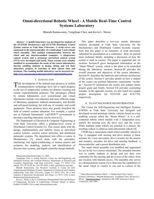
This paper describes a low-cost remote laboratory<br />
solution developed at <strong>Utah</strong> <strong>State</strong> <strong>University</strong> for the<br />
Mechatronics and Distributed Control Systems courses.<br />
Note that this paper is an extension of work previously<br />
submitted for presentation at a conference 1 . Here we present<br />
more technical details, including a discussion of how the<br />
system is used in courses. The paper is organized into six<br />
sections. Section-II gives background information on the<br />
“Smart <strong>Wheel</strong>” system, which is the plant to be controlled<br />
during the laboratory sessions. Section-III provides the<br />
overall structure and objectives of the course laboratory.<br />
Section-IV describes the hardware and software architecture<br />
of the system. Section-V provides details on how a student<br />
of the course can perform laboratory experiments “on-thego.”<br />
Section-VI summarizes the results and outlines future<br />
project goals and finally, Section-VII provides concluding<br />
remarks. In the appendix section, we also listed two sample<br />
project descriptions for ECE5320 and ECE7750,<br />
respectively.<br />
II. PLANT BACKGROUND INFORMATION<br />
The Center for Self-Organizing and Intelligent Systems<br />
(CSOIS) at <strong>Utah</strong> <strong>State</strong> <strong>University</strong> has designed and<br />
developed several prototype robotic vehicles based on a key<br />
enabling concept called the “Smart <strong>Wheel</strong>.” It is a selfcontained<br />
robotic wheel module with 3 independent axes,<br />
namely the steering axis, the drive axis, and the z-axis.<br />
When multiple smart wheels are attached to a chassis, the<br />
resulting vehicle is called an omni-<strong>directional</strong> vehicle [4].<br />
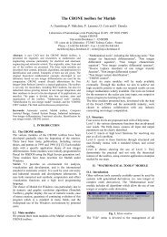
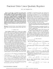
CSOIS has a stand-alone smart wheel assembly (shown in<br />
Fig. 1) equipped with steering and drive motors, a linear<br />
actuator for z-axis movement, drive circuitry for the motors<br />
and actuator, encoders for drive and steering feedback, a<br />
microcontroller, and a power distribution unit.<br />
The smart wheel assembly was modified and augmented<br />
for use in the two courses mentioned. The intended outcome<br />
was to enable students to design and test their own<br />
controllers for the steering and drive axes of the wheel, from<br />
any location with Internet access. The assembly also serves<br />
as a demonstration system [5] to showcase the capabilities of<br />
the smart wheel to visitors in situ and to visitors of the<br />
1 “<strong>Omni</strong>-<strong>directional</strong> <strong>Robotic</strong> <strong>Wheel</strong> - A Mobile Real-Time Control<br />
Systems Laboratory,” Bharath Ramaswamy, YangQuan Chen, and Kevin L.<br />
Moore, “Interactive Paper” submitted to the 2006 American Control<br />
Conference, June 2006.
CSOIS website. The smart wheel assembly also serves as a<br />
Fig. 1. Smart <strong>Wheel</strong> Assembly on a Mobile Rig.<br />
research test-bed for faculty and graduate students.<br />
III. SYSTEM OVERVIEW<br />
A. Networked Control Systems: An Introduction<br />
A networked control system is a feedback control system<br />
in which the control loop is closed through a communication<br />
network [6]. Such a system lends itself naturally to remote<br />
experimentation with the plant and feedback-sensor situated<br />
inside the university’s research center, the controller located<br />
on the remote student’s computer, and the communication<br />
network being the IP network between the plant/sensor and<br />
the controller.<br />
The objective of any networked control system is to use<br />
the finite network capacity while maintaining good closedloop<br />
performance, including stability, rise time, overshoot<br />
and other design criteria [6]. There are two approaches most<br />
commonly-used in the design of networked control systems<br />
[7]. One approach involves considering network-induced<br />
effects in the controller design for a given plant, set of<br />
design criteria and network protocol definition. The other<br />
approach involves making modifications to the network<br />
protocol for a given plant and controller (in this case, the<br />
controller is designed in advance without considering<br />
network-induced effects). The course laboratories described<br />
in this paper follow the first approach.<br />
B. Distributed Control Systems Design Laboratory<br />
In this course, the student is expected to design, test and<br />
demonstrate a working networked control system for the<br />
steering axis of the smart wheel.<br />
The serial port (RS232) on the smart wheel’s embedded<br />
controller was connected to an Ethernet Hub via a Serial<br />
Server, which translates messages between Ethernet and<br />
RS232 formats. The microcontroller on the wheel was<br />
programmed to poll the position encoder and transmit these<br />
values through its serial port. It also accepts velocity values<br />
via the serial port and converts them into pulse width<br />
modulated (PWM) signals to drive the motor.<br />
The student with the Internet-enabled computer at any<br />
remote location will install a virtual COM driver, in order to<br />
communicate with the smart wheel’s serial server. He can<br />
develop his control algorithm on the computer, which will<br />
transmit velocity values to the smart wheel, calculated based<br />
on the encoder readings received from the smart wheel. The<br />
Internet introduces random time delays and perturbations.<br />
These network-induced effects need to be taken into<br />
consideration while designing the controller, through the use<br />
of suitable techniques such as network prediction and delaycompensation.<br />
The closed-loop performance of the control<br />
system can be examined, by plotting the encoder data on the<br />
remote computer. Any windows-based environment may be<br />
used for development:<br />
C. Mechatronics Design Project Laboratory<br />
Since this is a course at the undergraduate-level, the<br />
students can design and test simple PID networked<br />
controllers for the steering and drive axes on their internetenabled<br />
computers, but without considering networkinduced<br />
effects into their design.<br />
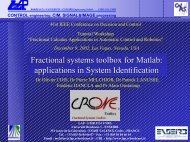
Figure 2 shows the user-interface for a prototype<br />
networked control system implemented for the steering axis<br />
of the smart wheel developed in Visual Basic. The set-point<br />
(steering angle) and controller gains (PID controller) are<br />
user-selectable and the user can view the system<br />
performance by observing the angular position plot that<br />
appears in real-time on the graphical display. An Internet<br />
camera streaming live video enables the student to view the<br />
wheel motion in real-time on the control panel.<br />
D. Demonstration System<br />
Fig. 2. Screen-shot of the Prototype Networked Control System<br />
Application.<br />
The microcontroller on the smart wheel also has its own<br />
set of control algorithms for the steering, drive and z-axes.<br />
In this case, the microcontroller accepts set-points from a
pair of joysticks or the remote computer for each of the three<br />
axes and controls the wheel according to its on-board<br />
control program. This feature enables the capabilities of the<br />
wheel to be showcased to local visitors and remote visitors<br />
to the CSOIS website when the wheel is not being used for<br />
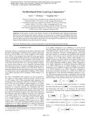
the course laboratories. Figure 3 shows the user-interface for<br />
the smart wheel’s telepresence control system.<br />
Fig. 3. Screen-shot of the Telepresence Control System Application.<br />
Suitable handshaking, control and arbitration protocols<br />
coordinate between joystick, telepresence and networked<br />
control modes, and also ensure predictable behavior when<br />
multiple users attempt to access the system.<br />
IV. SYSTEM DESCRIPTION<br />
The architecture of the stand-alone smart-wheel<br />
demonstration system [5] is shown in Fig. 4.<br />
A. Overall Plant Description<br />
The steering motor, drive motor, and linear actuator<br />
control the steering axis, drive axis, and z-axis of the smart<br />
wheel, respectively. The steering and drive motors are<br />
controlled by PWM and direction signals from their<br />
respective motor drivers. The steering motor is coupled to an<br />
absolute encoder, which measures the absolute angular<br />
Fig. 4. Smart <strong>Wheel</strong> System Overview.<br />
position of the wheel. The drive motor is attached to a<br />
quadrature encoder that measures the relative motion of the<br />
wheel. The linear actuator moves the entire steering column<br />
up or down along the linear slide. The linear potentiometer<br />
provides feedback about the z-position of the steering<br />
column. The z-axis control box commands the linear<br />
actuator based on the voltage value from the digital-toanalog<br />
converter (DAC) and the feedback from the linear<br />
potentiometer.<br />
B. Mechanical Hardware Description<br />
A cross-sectional view of the smart-wheel assembly<br />
(without z-axis actuator features) is shown in Fig. 5.<br />
The steering suspension supports the entire steering<br />
mechanism and wheel electronic systems. The steering<br />
spindle is directly coupled to the steering motor. The yoke<br />
fastens the drive assembly to the steering spindle. The yoke<br />
also houses the power and communications cables, which go<br />
down to the wheel. A custom slip ring allows infinite<br />
rotation of the wheel about the steering axis. The entire<br />
drive assembly including the drive spindle, motor, failsafe<br />
brake, and encoder is enclosed inside the wheel shell. The<br />
drive motor is a Kollmorgen model QT-6407 frameless<br />
torquer motor and the steering motor is a MicroMo series<br />
GNM 5440 PM DC motor. A CP-560 quadrature encoder<br />
from Computer Optical Products is used to measure relative<br />
wheel position. The absolute encoder used to measure<br />
absolute angular position of the steering motor in body-fixed<br />
coordinates is a Model 40H from Sequential Electronic<br />
Fig. 5. Smart <strong>Wheel</strong> Mechanical Assembly.<br />
Systems.<br />
Z-axis actuation capability was added by mounting the<br />
assembly shown in Fig. 5 on an Electrak linear actuator from<br />
Warner Electric. A linear potentiometer is mounted adjacent<br />
to the linear actuator near the top. The power distribution<br />
units are enclosed behind the damper. A control box for the<br />
z-axis movement is mounted on one side of the power<br />
distribution unit housing. The wheel electronics and motor<br />
drivers are mounted on either side of the steering column.<br />
The entire assembly is mounted on a wheeled stand. Refer to<br />
Fig. 1 again to see a complete picture of the system.
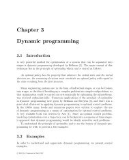
Fig. 6. DE-311 Serial Server (Image Courtesy: Moxa Technologies).<br />
C. Embedded Control Hardware Description<br />
The wheel node digital interface board consists of the<br />
Tattletale Model 8 (TT8), a microcontroller by Onset<br />
Computer Corporation [8] based on Motorola’s MC68332<br />
microprocessor. It also provides interfaces for serial<br />
communication, motor drivers, D/A and A/D converters, and<br />
absolute and quadrature encoders, circuits for power supply<br />
and regulation, level-shifting, and optical isolation, and the<br />
hardware watchdog unit.<br />
The steering and drive motors are each driven by a<br />
50A8DD Series PWM servo amplifier (or motor driver)<br />
from Advanced Motion Controls. The duty cycle of the<br />
pulse width modulated (PWM) signal determines the speed<br />
of the motor and the logic level of the direction signal<br />
determines the direction of rotation.<br />
A pair of joysticks interfaced to the A/D converter of the<br />
TT8, enable visitors to control the 3-axes of the wheel<br />
locally. One of them (Joystick-1) is a 3-axis joystick<br />
wherein the x-axis is used to set the drive speed and the<br />
twist axis is used to set the steering speed. Another singleaxis<br />
joystick (Joystick-2) is used to set the z-axis position.<br />
The plant components together with the embedded control<br />
hardware comprise the smart wheel assembly.<br />
D. Telepresence Control Hardware Description<br />
The smart wheel assembly is connected to the IP network<br />
via a serial server and an Ethernet switch. The serial server<br />
includes the hardware and embedded software for<br />
converting messages between RS232 and Ethernet formats.<br />
The DE-311 serial server (Fig. 6) from Moxa Technologies<br />
was used in the system [9] because of its low-cost, multi-OS<br />
portability (for future use), compatibility with 10BaseT and<br />
100BaseT Ethernet, and ease-of-use.<br />
A DCS5300 Internet camera from DLink (shown in Fig.<br />
7) located near the smart-wheel assembly directly sends<br />
streaming video and audio [10] of the smart wheel motion to<br />
the remote operator independent of the controller data<br />
(which uses the serial server). Like all internet cameras, it<br />
has a built-in web-server which captures and transmits live<br />
audio and video directly over the IP network, without the<br />
need for a direct connection to a PC. The camera’s features<br />
which include live video (30 fps at 640*480 resolution) and<br />
audio streaming (via its built-in microphone), as well as pan,<br />
tilt and zoom control capability, and ease of access made it<br />
an attractive choice. This off-the-shelf solution though not<br />
intended for this purpose, provides an immersive experience<br />
for the remote student, and also enables him/her to monitor<br />
the proper functioning and safety of the plant.<br />
However, because of the bandwidth intensive nature of<br />
the stream and the lack of priority control between the<br />
audio/video data and controller data, control system<br />
performance may be affected to varying extents depending<br />
on the remote computer’s processing power.<br />
Fig. 7. DLink Securicam DCS 5300 Internet Camera (Image<br />
Courtesy: DLink Corporation).<br />
E. Software Description<br />
The software architecture of the stand-alone smart-wheel<br />
demonstration system shown in Fig. 8 and consists of the<br />
following components:<br />
--Embedded software that resides on the TT8<br />
microcontroller board.<br />
--Video and audio buffering and streaming software on<br />
the Internet camera’s web server.<br />
--Embedded software on the serial server to convert<br />
messages between Ethernet and RS232 formats.<br />
--Virtual COM driver that allows communication<br />
between the student’s remote computer and the serial server<br />
that installs on the student’s remote computer.<br />
--Application software for telepresence and networked<br />
control of the 3-axes of the smart wheel that runs on the<br />
student’s remote computer.<br />
Of the above, the Virtual COM driver (Moxa tech.), the<br />
serial server embedded software (Moxa tech.), and the<br />
Internet camera webserver software (DLink corp.), have<br />
been provided by their respective manufacturers. The<br />
embedded software on the smart wheel’s TT8<br />
microcontroller board was developed at CSOIS. A<br />
telepresence controller and a prototype networked controller<br />
were also developed using Visual Basic for demonstration
Fig. 8. Smart <strong>Wheel</strong> Software Architecture.<br />
purposes at CSOIS.<br />
The software on the TT8 microcontroller [5] runs the<br />
system in one of four modes: the idle mode, the joystick<br />
mode, the telepresence mode and the networked control<br />
mode. In Idle mode, the system silently polls the joystick<br />
inputs and the serial ports for potential access requests.<br />
When a local user requests access (by pressing a button on<br />
the joystick panel), the system goes into joystick mode. In<br />
this mode, the on-board control algorithm commands the<br />
actuators based only on inputs from the joystick. When a<br />
remote user requests telepresence control access (by<br />
pressing a button on the GUI), the system transitions to<br />
telepresence mode. In this mode, the on-board control<br />
algorithm controls the wheel axes based on set-points<br />
received from the remote computer (by moving the 3-slider<br />
bars on the GUI). When a remote student requests<br />
networked laboratory access (by sending the appropriate<br />
access request command), the system goes into networked<br />
mode. In this mode, the on-board program sends sampled<br />
encoder readings along with the time-stamp and converts<br />
motor velocity values received from the remote computer<br />
into PWM signals for the motor driver hardware.<br />
The built-in arbitration mechanism sends appropriate<br />
rejection messages to remote requests when the smart wheel<br />
assembly is already being controlled by a local or another<br />
remote operator.<br />
V. LABORATORY STRUCTURE AND SET-UP<br />
Figure 9 depicts the laboratory setup for the networked<br />
control system design for the steering axis of the smart<br />
wheel as implemented during the Spring 2005 offering of<br />
the ECE7750 Distributed Control System course at <strong>Utah</strong><br />
<strong>State</strong> <strong>University</strong>. The project handout write-up is shown in<br />
Appendix-A.<br />
The student is required to install the virtual COM driver<br />
on his/her computer. This makes the smart wheel’s serial<br />
server appear to the computer as just another serial port. The<br />
only requirement is that the computer must have an active<br />
Internet connection, which could be wired or wireless. The<br />
suggested minimum system configuration is a Windows 98<br />
OS, Internet Explorer 5.x, Pentium-III 800 Mhz, 128Mb<br />
RAM, with a VGA Card 800*600.<br />
The protocol and packet structure have been provided to<br />
the students as part of the laboratory handouts [10, 11]. The<br />
procedure is summarized as follows:<br />
1. Remote terminal sends ncs_request command.<br />
2. Smart wheel sends ncs_accept command (if it was in<br />
idle mode) and goes into networked mode and resets<br />
its on-board timer.<br />
3. Smart wheel sends ncs_reject command if it was in<br />
already in joystick, telepresence or networked mode.<br />
4. If remote terminal reads an ncs_accept command, it<br />
initializes its controller and gets ready for incoming<br />
encoder feedback data packets.<br />
5. When smart wheel is in networked mode:<br />
a. It gets feedback values from encoder device<br />
driver and packs it in the format pq<br />
where is any value between -180 and<br />
-180 degrees.<br />
b. It gets timer values from the timer device driver<br />
and packs it in the format tu where<br />
represents time in milli-seconds relative<br />
to the reset performed in step (2).<br />
6. Smart wheel then sends the packed encoder value and<br />
corresponding time-stamp via the serial port.<br />
7. Remote terminal reads the above values from the<br />
virtual COM driver and unpacks the results and passes<br />
Fig. 9. Networked Control System Laboratory.<br />
it to the control program.<br />
8. The control program calculates a new velocity<br />
depending on the error and the networked control<br />
algorithm used.<br />
9. The new velocity is mapped to an appropriate ASCII<br />
character as follows:<br />
a. 70 to 100 for clockwise velocities (70 –<br />
stopped, 90 - maximum velocity).<br />
b. 70 to 40 for counter-clockwise velocities (70 –<br />
stopped, 50 - minimum velocity).<br />
10. The above value is transmitted to the smart wheel via<br />
the virtual COM drive and the serial server.<br />
11. Smart wheel reads the remote velocity, converts it to<br />
a duty-cycle (-1.0 and 1.0) and transmits it to the<br />
motor driver via the on-board timer peripheral.
12. When the smart wheel receives an ncs_complete<br />
command from the remote terminal, it halts the motor,<br />
and goes back into idle mode.<br />
The system response can be plotted on the student’s<br />
computer for performance-evaluation purposes. This enables<br />
the motion of the wheel axis to be viewed in real-time<br />
during development and testing. Up to twenty users can<br />
simultaneously view the wheel’s motion via the internet<br />
camera’s web-server.<br />
Since the protocol and packet format are simple and use<br />
only keyboard characters, the student can use a terminal<br />
emulator (like HyperTerminal) to communicate with the<br />
smart wheel’s embedded controller and get familiarized with<br />
the format of transmit and receive information, before<br />
getting started with controller design.<br />
This setup will also be used in the ECE5320<br />
Mechatronics course during Spring 2006 [12]. The proposed<br />
project handout write-up is shown in Appendix-B. The<br />
students can use the same system to design and test simple<br />
PID controllers, but they will not be expected to consider<br />
network-induced effects in their design. One suggested<br />
benchmarking exercise for the students will be to compare<br />
the system responses for a given controller on different<br />
remote-computers, different types of internet connections,<br />
and different locations.<br />
VI. RESULTS, ISSUES AND FUTURE WORK<br />
The system was used in the Spring 2005 offering of the<br />
Distributed Control Systems course at <strong>Utah</strong> <strong>State</strong> <strong>University</strong>.<br />
The students were able to successfully develop and test their<br />
networked control system designs from any wireless or<br />
wired internet-enabled computer at the time and place of<br />
their convenience. All students experienced this system and<br />
had gained deeper understanding about the overall NCS<br />
structure and the related control issues.<br />
It is proposed to extend the use of the smart wheel<br />
assembly for the Mechatronics course in the year 2006. At<br />
present, the embedded controller has been programmed to<br />
transmit encoder values at fixed intervals of 10ms and the<br />
serial configuration has been set to 9600 bps, 8 data bits, no<br />
parity, 1 stop bit, and no flow control. This has been done to<br />
enable low-speed computers to buffer and process the<br />
information without a system failure. A future upgrade with<br />
remotely-configurable parameters will enable high-end<br />
computers to take advantage of their processing power and<br />
obtain improved system response.<br />
At present the video/audio streaming of the laboratory<br />
plant uses a commercial off-the-self (COTS) solution which<br />
was not intended for use in remote laboratories.<br />
Requirements for remote experimentation streaming<br />
solutions differ from those required for videoconferencing<br />
and other similar applications in several ways. This includes<br />
the need to transmit the most recent information at the cost<br />
of discarding older data, emphasis on video over audio, etc.<br />
Also, since this is a bandwidth-intensive stream, viewing the<br />
video on same remote computer as the networked controller<br />
may significantly degrade the performance of the controller,<br />
depending on the processing power of the computer used.<br />
The data for motor commands, encoder feedback, session<br />
control, and audio/video streams have different QoS<br />
requirements. At present there is no control over the<br />
different types of data. When the relative priorities of the<br />
different streams are custom-managed, the controller<br />
performance degradation problem on account of the<br />
video/audio streaming can be solved [13].<br />
At present, the laboratory can only be done under the<br />
Windows environment. The student will be able to perform<br />
the laboratory on a Linux-based system as well, if we<br />
incorporate the custom streaming solution (described above)<br />
and a TTY driver to communicate with the serial server<br />
(instead of the present virtual COM driver).<br />
It is also proposed to extend the NCS laboratory to<br />
include velocity control of the drive axis of the smart wheel.<br />
This will enable the students to implement and experience<br />
different scheduling approaches for the steering and drive<br />
axis control threads, and deal with issues concerning the<br />
polling and commanding of multiple sensors and actuators<br />
(multirate control).<br />
VII. CONCLUSION<br />
This paper describes a cost-effective, self-contained and<br />
truly “mobile” embedded remote learning solution. By<br />
adding a low-cost serial server, the stand-alone robotic<br />
wheel assembly could be used for demonstration purposes,<br />
research in networked control systems, as well as control<br />
systems education.<br />
[1]<br />
REFERENCES<br />
D.Gillet, C.Salzmann, R.Longchamp, D.Bonvin, “Telepresence: An<br />
Opportunity to Develop Practical Experimentation in Automatic<br />
Control Education”, European Control Conference, 1997.<br />
[2] YangQuan Chen (January 2005). ECE 7750 Distributed Control<br />
Systems, <strong>Utah</strong> <strong>State</strong> <strong>University</strong>, Course website [Online]. Available:<br />
http://<strong>mechatronics</strong>.ece.usu.edu/ece7750/<br />
[3] YangQuan Chen (January 2005). ECE 5320 Mechatronics, <strong>Utah</strong> <strong>State</strong><br />
<strong>University</strong>, Course website [Online]: http://<strong>mechatronics</strong>.ece.usu.edu/<br />
[4] Nicholas Flann, Kevin Moore, “A Six-wheeled <strong>Omni</strong><strong>directional</strong><br />
Autonomous Mobile Robot,” IEEE Control Systems magazine, 2000.<br />
[5] Bharath Ramaswamy, “Embedded and Telepresence Control of a 3-<br />
Axis Smart <strong>Wheel</strong> Assembly,” M.S. thesis, Dept. Electrical and<br />
Computer. Eng., <strong>Utah</strong> <strong>State</strong> Univ., Logan, <strong>Utah</strong> USA, 2004.<br />
[6] Octavian Beldiman, “Networked Control Systems,” Ph.D.<br />
[7]<br />
Dissertation, Dept. Electrical and Computer. Eng., Duke Univ.,<br />
Durham, NC USA, 2001.<br />
Gragory Walsh, Linda G. Bushnell, Octavian Beldiman, Hong Ye,<br />
Caleb Belai, “Networked Control Systems”, Intelligent Control<br />
Engineering Laboratory, <strong>University</strong> of Maryland at College Park,<br />
USA, [Online]: http://www.enme.umd.edu/ice_lab/ncs/ncs.html<br />
[8] Onset Computer Corporation, Tattletale Model 8 Installation and<br />
Operation Manual, 1999.<br />
[9] NPort DE-311 Serial Device Server Solutions Datasheet, Moxa<br />
Technologies Co. Ltd., Taipei Taiwan.<br />
[10] DLink Securicam DCS 5300 Internet Camera Datasheet, DLink<br />
Systems Inc., Fountain Valley, CA USA, 2003.
[11] Networked Control Systems Design Laboratory, Project-1 for<br />
ECE7750 Distributed Control Systems, Course Laboratory Handout,<br />
Dept. Elect. Comp. Eng., <strong>Utah</strong> <strong>State</strong> Univ., Logan USA, 2005.<br />
[12] Networked Control Systems Design Laboratory, Project for ECE5320<br />
Mechatronics, Course Laboratory Handout, Dept. Elect. Comp. Eng.,<br />
<strong>Utah</strong> <strong>State</strong> Univ., Logan USA, 2006.<br />
[13] Ch.Salzmann, H.A.Latchman, D.Gillet, O.D.Crisalle, “Requirements<br />
for Real-Time Laboratory Experimentation Over the Internet”,<br />
International Conference on Engineering Education, 1998.
Appendix-A<br />
ECE 7750 DISTRIBUTED CONTROL SYSTEMS<br />
DEPARTMENT OF ELECTRICAL & COMPUTER<br />
ENGINEERING, UTAH STATE UNIVERSITY<br />
SPRING 2005<br />
PROJECT: Design and Implementation of a Networked<br />
Control System for a Stand-Alone Smart <strong>Wheel</strong><br />
Assembly<br />
Objective<br />
To design and implement a Networked Control System to<br />
control the angular position of the steering axis of the smartwheel.<br />
Introduction to the System<br />
The Smartwheel at CSOIS is a self-contained wheel<br />
module with separate drive and steering motors as well as a<br />
linear actuator, which enables the wheel to be moved along<br />
the z-axis. It is equipped with PWM Amplifiers for the<br />
Steering and Drive motors and Absolute and Quadrature<br />
encoders to measure the steering and drive axes’ positions<br />
respectively. A <strong>Wheel</strong> Node Digital Interface board<br />
accommodates a Motorola 68332-based Tattletale TT8<br />
controller along with interfaces to the motor drivers, serial<br />
communication, absolute and quadrature encoders, circuits<br />
for power supply and regulation, level-shifting, and optical<br />
isolation, and the hardware watchdog unit.<br />
For this project, only the steering axis will be controlled.<br />
The steering motor is controlled by feeding PWM and<br />
direction signals to its PWM amplifier. The steering motor is<br />
coupled to an absolute encoder, which measures the absolute<br />
angular position of the wheel.<br />
You can communicate with the smart wheel through a<br />
device known as the serial server, which converts messages<br />
from RS232 format into TCP/IP format and vice-versa. You<br />
need to install a Virtual COM Driver on your development<br />
terminal in order to communicate with the smart wheel. This<br />
will make the serial server appear to your computer as just<br />
another serial port.<br />
Command and Communication Protocol:<br />
Your controller will obtain access to the smartwheel upon<br />
sending the REMOTE_REQ (ASCII: 47) character. The<br />
smartwheel will respond with an REMOTE_ACCEPT<br />
(ASCII: 33) character to indicate that it is ready to receive<br />
motor commands and a REMOTE_REJECT (ASCII: 35)<br />
command if it is busy.<br />
The steering motor rotates in one direction when it<br />
receives ASCII values 70 to 90 (70 - Stopped, 90 –<br />
Maximum Speed). It rotates in the opposite direction when it<br />
receives ASCII values 70 to 50 (70 - Stopped, 50 –<br />
Maximum Speed).<br />
At approximately equal intervals, the TT8 controller<br />
samples the absolute encoder and transmits data to the<br />
remote terminal in the following format:<br />
tu<br />
pq<br />
where:<br />
represents the time of sampling (relative to receipt<br />
of the REMOTE_REQ command) in millisecs.<br />
represents the wheel orientation in degrees at time<br />
.<br />
The wheel will halt rotation upon receipt of ASCII value:<br />
92. Do use this command at the end of your control session<br />
and also, implement an Emergency Stop! To resume access,<br />
the REMOTE_REQ character has to be sent again.<br />
It is a good idea to use a terminal emulator such as<br />
HyperTerminal to communicate with the smartwheel before<br />
beginning NCS development (Use this configuration: 9600<br />
BPS, 8 data bits, No Parity, 1 Stop bit, No Flow control).<br />
Motion Video<br />
An Internet camera located near the smart wheel assembly<br />
directly sends streaming video and audio of the smart wheel<br />
motion to the remote operator. This will enable you to view<br />
the motion of the wheel axis in real-time during<br />
development and testing. The video can be accessed at this<br />
URL: http://129.123.85.37/. Enter ‘user1’ as user-name and<br />
‘guest’ as password when prompted. You may be asked to<br />
download a ‘DLink Audio Control’ before you obtain access<br />
to the camera’s video.<br />
Lab Requirements<br />
Implement a Networked Control System with a PID<br />
Controller to control the steering position of the smart wheel<br />
using the available hardware. You can use any software<br />
platform of your choice. Your software should plot the<br />
system response in real-time and preferably be a selfcontained<br />
application. You must consider network-induced<br />
effects and use the techniques learned in the course in your<br />
design. Run the controller for different set-points and<br />
controller gains and evaluate the system performance.<br />
On the due date (TBD), you will be required to<br />
demonstrate your system to the class. You should also turnin<br />
a report which includes your design, software platform<br />
used, and controller-performance evaluation. You may work<br />
in groups of up to three members.<br />
Before you begin:<br />
Download the Client software installation files from the<br />
location:<br />
http://csois.usu.edu/people/smartwheel/CompleteInfoPage.htm<br />
and follow all the instructions for installation of the Virtual<br />
COM Driver and the Networked Control Laboratory<br />
demonstration software.
Appendix-B<br />
ECE 5320 MECHATRONICS<br />
DEPARTMENT OF ELECTRICAL & COMPUTER<br />
ENGINEERING, UTAH STATE UNIVERSITY<br />
SPRING 2006<br />
PROJECT: Design and Implementation of a Networked<br />
Control System for a Stand-Alone Smart <strong>Wheel</strong><br />
Assembly<br />
Objective:<br />
To implement a Networked Control System to control the<br />
angular position of the steering axis of the smart-wheel.<br />
Introduction to the System:<br />
The Smartwheel at CSOIS is a self-contained wheel<br />
module with separate drive and steering motors as well as a<br />
linear actuator, which enables the wheel to be moved along<br />
the z-axis.<br />
It is equipped with PWM Amplifiers for the Steering and<br />
Drive motors and Absolute and Quadrature encoders to<br />
measure the steering and drive axes’ positions respectively.<br />
A <strong>Wheel</strong> Node Digital Interface board accommodates a<br />
Motorola 68332-based Tattletale TT8 controller along with<br />
interfaces to the motor drivers, serial communication,<br />
absolute and quadrature encoders, circuits for power supply<br />
and regulation, level-shifting, and optical isolation, and the<br />
hardware watchdog unit.<br />
For this project, only the steering axis will be controlled.<br />
The steering motor is controlled by feeding PWM and<br />
direction signals to its PWM amplifier. The steering motor is<br />
coupled to an absolute encoder, which measures the absolute<br />
angular position of the wheel.<br />
You can communicate with the smart wheel through a<br />
device known as the serial server, which converts messages<br />
from RS232 format into TCP/IP format and vice-versa. You<br />
need to install a Virtual COM Driver on your development<br />
terminal in order to communicate with the smart wheel. This<br />
will make the serial server appear to your computer as just<br />
another serial port.<br />
Command and Communication Protocol:<br />
Your controller will obtain access to the smartwheel upon<br />
sending the REMOTE_REQ (ASCII: 47) character. The<br />
smartwheel will respond with an REMOTE_ACCEPT<br />
(ASCII: 33) character to indicate that it is ready to receive<br />
motor commands and a REMOTE_REJECT (ASCII: 35)<br />
command if it is busy.<br />
The steering motor rotates in one direction when it<br />
receives ASCII values 70 to 90 (70 - Stopped, 90 –<br />
Maximum Speed). It rotates in the opposite direction when it<br />
receives ASCII values 70 to 50 (70 - Stopped, 50 –<br />
Maximum Speed).<br />
At approximately equal intervals, the TT8 controller<br />
samples the absolute encoder and transmits data to the<br />
remote terminal in the following format:<br />
tu<br />
pq<br />
where:<br />
represents the time of sampling (relative to receipt of<br />
the REMOTE_REQ command) in millisecs.<br />
represents the wheel orientation in degrees at time<br />
.<br />
The wheel will halt rotation upon receipt of ASCII value:<br />
92. Do use this command at the end of your control session<br />
and also, implement an Emergency Stop! To resume access,<br />
the REMOTE_REQ character has to be sent again.<br />
It is a good idea to use a terminal emulator such as<br />
HyperTerminal to communicate with the smartwheel before<br />
beginning NCS development (Use this configuration: 9600<br />
BPS, 8 data bits, No Parity, 1 Stop bit, No Flow control).<br />
Motion Video:<br />
An Internet camera located near the smart wheel assembly<br />
directly sends streaming video and audio of the smart wheel<br />
motion to the remote operator. This will enable you to view<br />
the motion of the wheel axis in real-time during<br />
development and testing. The video can be accessed at this<br />
URL: http://129.123.85.37/. Enter ‘user1’ as user-name and<br />
‘guest’ as password when prompted. You may be asked to<br />
download a ‘DLink Audio Control’ before you obtain access<br />
to the camera’s video.<br />
Lab Requirements:<br />
Implement a PID Controller to control the steering position<br />
of the smart wheel using the available hardware. You can<br />
use any software platform of your choice. Your software<br />
should plot the system response in real-time and preferably<br />
be a self-contained application. The Internet may introduce<br />
random time delays and perturbations. You need not<br />
consider these network-induced effects in your design. Run<br />
the controller for different set-points and controller gains<br />
and evaluate the system performance. Compare the system<br />
responses for a given controller on remote-computers with<br />
different hardware configurations, different types of internet<br />
connections, and from different locations.<br />
On the due date (TBD), you will be required to demonstrate<br />
your system to the class. You should also submit a report<br />
which includes your design, software platform used, and<br />
controller-performance evaluation. You may work in groups<br />
of up to three members.<br />
Before you begin:<br />
Download the Client software installation files from the<br />
location:<br />
http://csois.usu.edu/people/smartwheel/CompleteInfoPage.htm and<br />
follow all the instructions for installation of the Virtual<br />
COM Driver and the Networked Control Laboratory<br />
demonstration software.