LM13700 Dual Operational Transconductance ... - MIT Media Lab
LM13700 Dual Operational Transconductance ... - MIT Media Lab
LM13700 Dual Operational Transconductance ... - MIT Media Lab

You also want an ePaper? Increase the reach of your titles
YUMPU automatically turns print PDFs into web optimized ePapers that Google loves.
<strong>LM13700</strong><br />
Additional Applications (Continued)<br />
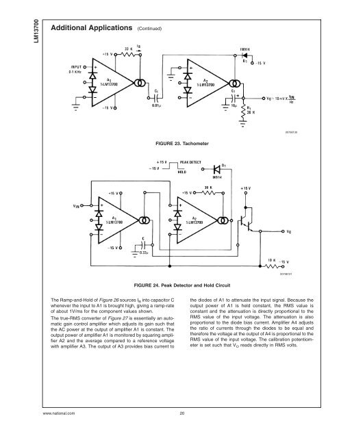
The Ramp-and-Hold of Figure 26 sources IB into capacitor C<br />
whenever the input to A1 is brought high, giving a ramp-rate<br />
of about 1V/ms for the component values shown.<br />
The true-RMS converter of Figure 27 is essentially an automatic<br />
gain control amplifier which adjusts its gain such that<br />
the AC power at the output of amplifier A1 is constant. The<br />
output power of amplifier A1 is monitored by squaring amplifier<br />
A2 and the average compared to a reference voltage<br />
with amplifier A3. The output of A3 provides bias current to<br />
FIGURE 23. Tachometer<br />
FIGURE 24. Peak Detector and Hold Circuit<br />
www.national.com 20<br />
00798130<br />
00798131<br />
the diodes of A1 to attenuate the input signal. Because the<br />
output power of A1 is held constant, the RMS value is<br />
constant and the attenuation is directly proportional to the<br />
RMS value of the input voltage. The attenuation is also<br />
proportional to the diode bias current. Amplifier A4 adjusts<br />
the ratio of currents through the diodes to be equal and<br />
therefore the voltage at the output of A4 is proportional to the<br />
RMS value of the input voltage. The calibration potentiometer<br />
is set such that V O reads directly in RMS volts.