NE/SA/SE555/SE555C Timer - Datasheet Catalog
NE/SA/SE555/SE555C Timer - Datasheet Catalog
NE/SA/SE555/SE555C Timer - Datasheet Catalog

You also want an ePaper? Increase the reach of your titles
YUMPU automatically turns print PDFs into web optimized ePapers that Google loves.
<strong>NE</strong>/<strong>SA</strong>/<strong>SE555</strong>/<strong>SE555</strong>C<br />
<strong>Timer</strong><br />
Product data<br />
Supersedes data of 1994 Aug 31<br />
<br />
<br />
INTEGRATED CIRCUITS<br />
2003 Feb 14
Philips Semiconductors Product data<br />
<strong>Timer</strong><br />
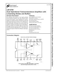
DESCRIPTION<br />
The 555 monolithic timing circuit is a highly stable controller capable<br />
of producing accurate time delays, or oscillation. In the time delay<br />
mode of operation, the time is precisely controlled by one external<br />
resistor and capacitor. For a stable operation as an oscillator, the<br />
free running frequency and the duty cycle are both accurately<br />
controlled with two external resistors and one capacitor. The circuit<br />
may be triggered and reset on falling waveforms, and the output<br />
structure can source or sink up to 200 mA.<br />
FEATURES<br />
• Turn-off time less than 2 μs<br />
• Max. operating frequency greater than 500 kHz<br />
• Timing from microseconds to hours<br />
• Operates in both astable and monostable modes<br />
• High output current<br />
• Adjustable duty cycle<br />
• TTL compatible<br />
• Temperature stability of 0.005% per °C<br />
APPLICATIONS<br />
• Precision timing<br />
• Pulse generation<br />
• Sequential timing<br />
• Time delay generation<br />
• Pulse width modulation<br />
ORDERING INFORMATION<br />
2003 Feb 14<br />
2<br />
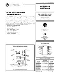
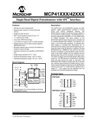
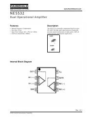
PIN CONFIGURATION<br />
BLOCK DIAGRAM<br />
THRESHOLD<br />
DISCHARGE<br />
<strong>NE</strong>/<strong>SA</strong>/<strong>SE555</strong>/<strong>SE555</strong>C<br />
D and N Packages<br />
GND 1<br />
8 VCC TRIGGER 2<br />
7 DISCHARGE<br />
OUTPUT 3<br />
6 THRESHOLD<br />
RESET 4 5 CONTROL VOLTAGE<br />
7<br />
6<br />
SL00349<br />
Figure 1. Pin configuration<br />
COMPARATOR<br />
OUTPUT<br />
STAGE<br />
V CC<br />
8<br />
R<br />
R<br />
FLIP FLOP<br />
3 1<br />
COMPARATOR<br />
R<br />
OUTPUT GND<br />
Figure 2. Block Diagram<br />
5<br />
2<br />
4<br />
CONTROL<br />
VOLTAGE<br />
TRIGGER<br />
RESET<br />
SL00350<br />
DESCRIPTION TEMPERATURE RANGE ORDER CODE DWG #<br />
8-Pin Plastic Small Outline (SO) Package 0 to +70 °C <strong>NE</strong>555D SOT96-1<br />
8-Pin Plastic Dual In-Line Package (DIP) 0 to +70 °C <strong>NE</strong>555N SOT97-1<br />
8-Pin Plastic Small Outline (SO) Package –40 °C to +85 °C <strong>SA</strong>555D SOT96-1<br />
8-Pin Plastic Dual In-Line Package (DIP) –40 °C to +85 °C <strong>SA</strong>555N SOT97-1<br />
8-Pin Plastic Dual In-Line Package (DIP) –55 °C to +125 °C <strong>SE555</strong>CN SOT97-1<br />
8-Pin Plastic Dual In-Line Package (DIP) –55 °C to +125 °C <strong>SE555</strong>N SOT97-1
Philips Semiconductors Product data<br />
<strong>Timer</strong><br />
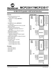
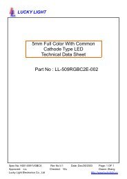
EQUIVALENT SCHEMATIC<br />
V CC<br />
THRESHOLD<br />
TRIGGER<br />
RESET<br />
DISCHARGE<br />
GND<br />
NOTE: Pin numbers are for 8-Pin package<br />
R1<br />
4.7 kΩ<br />
R2<br />
330 Ω<br />
R3<br />
4.7 kΩ<br />
2003 Feb 14 3<br />
Q5<br />
Q14<br />
ABSOLUTE MAXIMUM RATINGS<br />
Q1<br />
Q25<br />
Q6<br />
Q7<br />
Q2 Q3<br />
R5<br />
10 kΩ<br />
Q4<br />
Q8<br />
Q9<br />
R4<br />
1 kΩ<br />
R8<br />
5 kΩ<br />
Q11 Q12<br />
Q10<br />
Q13<br />
R6<br />
100 kΩ<br />
R16<br />
100 Ω<br />
R9<br />
5 kΩ<br />
R7<br />
5 kΩ<br />
CB<br />
Q18<br />
E<br />
Q15<br />
Figure 3. Equivalent schematic<br />
FM<br />
Q16<br />
<strong>NE</strong>/<strong>SA</strong>/<strong>SE555</strong>/<strong>SE555</strong>C<br />
CONTROL VOLTAGE<br />
R10<br />
82 kΩ<br />
R11<br />
4.7 kΩ<br />
Q17<br />
Q19<br />
Q20<br />
R12<br />
6.8<br />
kΩ<br />
Q21<br />
R13<br />
3.9 kΩ<br />
Q23<br />
C B<br />
R14<br />
220 Ω<br />
R15<br />
4.7 kΩ<br />
Q22<br />
Q24<br />
SL00351<br />
OUTPUT<br />
SYMBOL PARAMETER RATING UNIT<br />
Supply voltage<br />
V CC <strong>SE555</strong> +18 V<br />
<strong>NE</strong>555, <strong>SE555</strong>C, <strong>SA</strong>555 +16 V<br />
P D Maximum allowable power dissipation 1 600 mW<br />
T amb<br />
Operating ambient temperature range<br />
<strong>NE</strong>555 0 to +70 °C<br />
<strong>SA</strong>555 –40 to +85 °C<br />
<strong>SE555</strong>, <strong>SE555</strong>C –55 to +125 °C<br />
T stg Storage temperature range –65 to +150 °C<br />
TSOLD Lead soldering temperature (10 sec max) +230 °C<br />
NOTE:<br />
1. The junction temperature must be kept below 125 °C for the D package and below 150°C for the N package.<br />
At ambient temperatures above 25 °C, where this limit would be derated by the following factors:<br />
D package 160 °C/W<br />
N package 100 °C/W
Philips Semiconductors Product data<br />
<strong>Timer</strong><br />
DC AND AC ELECTRICAL CHARACTERISTICS<br />
T amb = 25 °C, V CC = +5 V to +15 V unless otherwise specified.<br />
SYMBOL PARAMETER TEST CONDITIONS<br />
2003 Feb 14 4<br />
<strong>NE</strong>/<strong>SA</strong>/<strong>SE555</strong>/<strong>SE555</strong>C<br />
<strong>SE555</strong> <strong>NE</strong>555/<strong>SA</strong>555/<strong>SE555</strong>C<br />
Min Typ Max Min Typ Max<br />
V CC Supply voltage 4.5 18 4.5 16 V<br />
ICC Supply current (low state) 1 VCC = 5 V, RL = ∞ 3 5 3 6 mA<br />
ICC Su ly current (low state)<br />
VCC = 15 V, RL = ∞ 10 12 10 15 mA<br />
Timing error (monostable) R A = 2 kΩ to 100 kΩ<br />
t M Initial accuracy 2 C=0.1 μF 0.5 2.0 1.0 3.0 %<br />
Δt M/ΔT Drift with temperature 30 100 50 150 ppm/°C<br />
Δt M/ΔV S Drift with supply voltage 0.05 0.2 0.1 0.5 %/V<br />
Timing error (astable) R A, R B = 1 kΩ to 100 kΩ<br />
t A Initial accuracy 2 C = 0.1 μF 4 6 5 13 %<br />
Δt A/ΔT Drift with temperature V CC = 15 V 500 500 ppm/°C<br />
Δt A/ΔV S Drift with supply voltage 0.15 0.6 0.3 1 %/V<br />
V C<br />
V TH<br />
Control voltage level<br />
Threshold voltage<br />
UNIT<br />
VCC = 15 V 9.6 10.0 10.4 9.0 10.0 11.0 V<br />
VCC = 5 V 2.9 3.33 3.8 2.6 3.33 4.0 V<br />
VCC = 15 V 9.4 10.0 10.6 8.8 10.0 11.2 V<br />
VCC = 5 V 2.7 3.33 4.0 2.4 3.33 4.2 V<br />
I TH Threshold current 3 0.1 0.25 0.1 0.25 μA<br />
V TRIG<br />
Trigger voltage<br />
VCC = 15 V 4.8 5.0 5.2 4.5 5.0 5.6 V<br />
VCC = 5 V 1.45 1.67 1.9 1.1 1.67 2.2 V<br />
I TRIG Trigger current V TRIG = 0 V 0.5 0.9 0.5 2.0 μA<br />
V RESET Reset voltage 4 V CC = 15 V, V TH = 10.5 V 0.3 1.0 0.3 1.0 V<br />
I RESET<br />
V VOOL Reset current VRESET = 0.4 V 0.1 0.4 0.1 0.4 mA<br />
Reset current VRESET = 0 V 0.4 1.0 0.4 1.5 mA<br />
LOW LOW-level level output voltage<br />
VCC = 15 V<br />
ISINK = 10 mA 0.1 0.15 0.1 0.25 V<br />
ISINK = 50 mA 0.4 0.5 0.4 0.75 V<br />
ISINK = 100 mA 2.0 2.2 2.0 2.5 V<br />
ISINK = 200 mA 2.5 2.5 V<br />
V CC = 5 V<br />
I SINK = 8 mA 0.1 0.25 0.3 0.4 V<br />
I SINK = 5 mA 0.05 0.2 0.25 0.35 V<br />
VCC = 15 V<br />
ISOURCE = 200 mA 12.5 12.5 V<br />
V OH HIGH-level output voltage g<br />
ISOURCE = 100 mA<br />
VCC = 5 V<br />
13.0 13.3 12.75 13.3 V<br />
ISOURCE = 100 mA 3.0 3.3 2.75 3.3 V<br />
t OFF Turn-off time 5 V RESET = V CC 0.5 2.0 0.5 2.0 μs<br />
t R Rise time of output 100 200 100 300 ns<br />
t F Fall time of output 100 200 100 300 ns<br />
Discharge leakage current 20 100 20 100 nA<br />
NOTES:<br />
1. Supply current when output high typically 1 mA less.<br />
2. Tested at VCC = 5 V and VCC = 15 V.<br />
3. This will determine the max value of RA+RB, for 15 V operation, the max total R = 10 MΩ, and for 5 V operation, the max. total R = 3.4 MΩ.<br />
4. Specified with trigger input HIGH.<br />
5. Time measured from a positive-going input pulse from 0 to 0.8×VCC into the threshold to the drop from HIGH to LOW of the output. Trigger is<br />
tied to threshold.
Philips Semiconductors Product data<br />
<strong>Timer</strong><br />
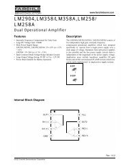
TYPICAL PERFORMANCE CHARACTERISTICS<br />
MINIMUM PULSE WIDTH (ns)<br />
V OUT – VOLTS<br />
V OUT – VOLTS<br />
CC<br />
V<br />
150<br />
125<br />
100<br />
75<br />
50<br />
25<br />
0<br />
Minimum Pulse Width<br />
Required for Triggering<br />
+70 °C<br />
–55 °C<br />
0 °C<br />
+25 °C<br />
+125 °C<br />
0 0.1 0.2 0.3 0.4 (×VCC )<br />
LOWEST VOLTAGE LEVEL OF TRIGGER PULSE<br />
10<br />
1.0<br />
0.1<br />
Low Output Voltage<br />
vs Output Sink Current<br />
0.001<br />
1.0 2.0 5.0 10 20 50 100<br />
2.0<br />
1.8<br />
1.6<br />
1.4<br />
1.2<br />
1.0<br />
0.8<br />
0.6<br />
0.4<br />
0.2<br />
0<br />
–55 °C<br />
High Output Voltage Drop<br />
vs Output Source Current<br />
1.0 2.0 5.0 10 20 50 100<br />
2003 Feb 14 5<br />
SUPPLY CURRENT – mA<br />
V OUT – VOLTS<br />
10.0<br />
8.0<br />
6.0<br />
4.0<br />
2.0<br />
0<br />
10<br />
1.0<br />
0.1<br />
0.01<br />
1.015<br />
1.010<br />
1.005<br />
1.000<br />
Supply Current<br />
vs Supply Voltage<br />
5.0 10.0<br />
SUPPLY VOLTAGE – VOLTS<br />
15.0<br />
Low Output Voltage<br />
vs Output Sink Current<br />
1.0 2.0 5.0 10 20 50 100<br />
Delay Time<br />
vs Supply Voltage<br />
NORMALIZED DELAY TIME<br />
V OUT – VOLTS<br />
<strong>NE</strong>/<strong>SA</strong>/<strong>SE555</strong>/<strong>SE555</strong>C<br />
1.015<br />
1.010<br />
1.005<br />
1.000<br />
0.995<br />
0.990<br />
0.985<br />
10<br />
1.0<br />
0.1<br />
0.01<br />
Delay Time<br />
vs Temperature<br />
-50 -25 0 +25 +50 +75 +100 +125<br />
TEMPERATURE – °C<br />
Low Output Voltage<br />
vs Output Sink Current<br />
1.0 2.0 5.0 10 20 50 100<br />
I SINK – mA I SINK – mA I SINK – mA<br />
–55 °C<br />
+25 °C<br />
+125 °C<br />
V CC = 5 V<br />
+25 °C<br />
+25 °C<br />
5 V ≤ V CC ≤ 15 V<br />
NORMALIZED DELAY TIME<br />
+25 °C<br />
+125 °C<br />
–55 °C<br />
+25 °C<br />
+25 °C<br />
V CC = 10 V V CC = 15 V<br />
–55 °C<br />
+25 °C<br />
–55 °C<br />
PROPAGATION DELAY – ns<br />
Propagation Delay vs Voltage<br />
Level of Trigger Pulse<br />
0.995<br />
100<br />
+25 °C<br />
+70 °C<br />
0.990<br />
50<br />
+25 °C<br />
0.985<br />
0<br />
0 5 10 15 20 0 0.1 0.2 0.3 0.4<br />
ISOURCE – mA SUPPLY VOLTAGE – V LOWEST VOLTAGE LEVEL<br />
OF TRIGGER PULSE – ×VCC SL00352<br />
+25 °C<br />
Figure 4. Typical Performance Characteristics<br />
300<br />
250<br />
200<br />
150<br />
+25 °C<br />
0 °C<br />
–55 °C<br />
+25 °C<br />
–55 °C<br />
–55 °C
Philips Semiconductors Product data<br />
<strong>Timer</strong><br />
TYPICAL APPLICATIONS<br />
0.01 μF<br />
0.01 μF<br />
DISCHARGE<br />
CONTROL<br />
VOLTAGE<br />
THRESHOLD<br />
TRIGGER<br />
DISCHARGE<br />
CONTROL<br />
VOLTAGE<br />
THRESHOLD<br />
1<br />
3 V CC<br />
TRIGGER<br />
COMP<br />
COMP<br />
555 OR 1/2 556<br />
2003 Feb 14 6<br />
R B<br />
C<br />
C<br />
R A<br />
7<br />
5<br />
6<br />
2<br />
R A<br />
7<br />
5<br />
6<br />
2<br />
V CC<br />
8<br />
R<br />
V CC<br />
R<br />
8<br />
R<br />
R<br />
R<br />
R<br />
COMP<br />
COMP<br />
555 OR 1/2 556<br />
FLIP<br />
FLOP<br />
Astable Operation<br />
4<br />
RESET<br />
FLIP<br />
FLOP<br />
4<br />
RESET<br />
OUTPUT<br />
OUTPUT<br />
<strong>NE</strong>/<strong>SA</strong>/<strong>SE555</strong>/<strong>SE555</strong>C<br />
3<br />
OUTPUT<br />
1.49<br />
f <br />
(R<br />
A<br />
2R<br />
B<br />
)C<br />
3<br />
OUTPUT<br />
ΔT = 1.1RC<br />
Monostable Operation SL00353<br />
Figure 5. Typical Applications<br />
| Δt |
Philips Semiconductors Product data<br />
<strong>Timer</strong><br />
TYPICAL APPLICATIONS<br />
V CC<br />
0.001 μF<br />
2003 Feb 14 7<br />
V CC<br />
10 kΩ<br />
2 555<br />
1/3 V CC<br />
0 VOLTS<br />
Trigger Pulse Width Requirements and Time<br />
Delays<br />
Due to the nature of the trigger circuitry, the timer will trigger on the<br />
negative going edge of the input pulse. For the device to time out<br />
properly, it is necessary that the trigger voltage level be returned to<br />
some voltage greater than one third of the supply before the time out<br />
period. This can be achieved by making either the trigger pulse<br />
sufficiently short or by AC coupling into the trigger. By AC coupling<br />
the trigger, see Figure 6, a short negative going pulse is achieved<br />
when the trigger signal goes to ground. AC coupling is most<br />
frequently used in conjunction with a switch or a signal that goes to<br />
ground which initiates the timing cycle. Should the trigger be held<br />
low, without AC coupling, for a longer duration than the timing cycle<br />
the output will remain in a high state for the duration of the low<br />
trigger signal, without regard to the threshold comparator state. This<br />
is due to the predominance of Q 15 on the base of Q 16, controlling<br />
the state of the bi-stable flip-flop. When the trigger signal then<br />
returns to a high level, the output will fall immediately. Thus, the<br />
output signal will follow the trigger signal in this case.<br />
V CC<br />
SWITCH GROUNDED<br />
AT THIS POINT<br />
Figure 6. AC Coupling of the Trigger Pulse<br />
<strong>NE</strong>/<strong>SA</strong>/<strong>SE555</strong>/<strong>SE555</strong>C<br />
1<br />
DURATION OF<br />
TRIGGER PULSE AS<br />
SEEN BY THE TIMER<br />
SL00354<br />
Another consideration is the “turn-off time”. This is the measurement<br />
of the amount of time required after the threshold reaches 2/3 V CC<br />
to turn the output low. To explain further, Q 1 at the threshold input<br />
turns on after reaching 2/3 V CC, which then turns on Q 5, which turns<br />
on Q 6. Current from Q 6 turns on Q 16 which turns Q 17 off. This<br />
allows current from Q 19 to turn on Q 20 and Q 24 to given an output<br />
low. These steps cause the 2 μs max. delay as stated in the data<br />
sheet.<br />
Also, a delay comparable to the turn-off time is the trigger release<br />
time. When the trigger is low, Q 10 is on and turns on Q 11 which turns<br />
on Q 15. Q 15 turns off Q 16 and allows Q 17 to turn on. This turns off<br />
current to Q 20 and Q 24, which results in output high. When the<br />
trigger is released, Q 10 and Q 11 shut off, Q 15 turns off, Q 16 turns on<br />
and the circuit then follows the same path and time delay explained<br />
as “turn off time”. This trigger release time is very important in<br />
designing the trigger pulse width so as not to interfere with the<br />
output signal as explained previously.
Philips Semiconductors Product data<br />
<strong>Timer</strong><br />
2003 Feb 14 8<br />
<strong>NE</strong>/<strong>SA</strong>/<strong>SE555</strong>/<strong>SE555</strong>C<br />
SO8: plastic small outline package; 8 leads; body width 3.9 mm SOT96-1
Philips Semiconductors Product data<br />
<strong>Timer</strong><br />
2003 Feb 14 9<br />
<strong>NE</strong>/<strong>SA</strong>/<strong>SE555</strong>/<strong>SE555</strong>C<br />
DIP8: plastic dual in-line package; 8 leads (300 mil) SOT97-1
Philips Semiconductors Product data<br />
<strong>Timer</strong><br />
REVISION HISTORY<br />
Rev Date Description<br />
_2 20030214 Product data (9397 750 11129); ECN 853-0036 29156 of 06 November 2002.<br />
Supersedes Product specification dated August 31, 1994.<br />
2003 Feb 14 10<br />
<strong>NE</strong>/<strong>SA</strong>/<strong>SE555</strong>/<strong>SE555</strong>C<br />
Modifications:<br />
• Remove all cerdip information from the data sheet. Package type discontinued.<br />
• ‘Absolute maximum ratings’ table: T SOLD rating changed from ‘+300 °C’ to ‘+230 °C’.<br />
19940831 Product specification; ECN 853-0036 13721 of 31 August 1994.<br />
(Filename = <strong>NE</strong>_<strong>SA</strong>555X.pdf)
Philips Semiconductors Product data<br />
<strong>Timer</strong><br />
Data sheet status<br />
Level<br />
I<br />
II<br />
III<br />
Data sheet status [1]<br />
Objective data<br />
Preliminary data<br />
Product data<br />
2003 Feb 14 11<br />
<strong>NE</strong>/<strong>SA</strong>/<strong>SE555</strong>/<strong>SE555</strong>C<br />
Definitions<br />
Short-form specification — The data in a short-form specification is extracted from a full data sheet with the same type number and title. For detailed information see<br />
the relevant data sheet or data handbook.<br />
Limiting values definition — Limiting values given are in accordance with the Absolute Maximum Rating System (IEC 60134). Stress above one or more of the limiting<br />
values may cause permanent damage to the device. These are stress ratings only and operation of the device at these or at any other conditions above those given<br />
in the Characteristics sections of the specification is not implied. Exposure to limiting values for extended periods may affect device reliability.<br />
Application information — Applications that are described herein for any of these products are for illustrative purposes only. Philips Semiconductors make no<br />
representation or warranty that such applications will be suitable for the specified use without further testing or modification.<br />
Disclaimers<br />
Life support — These products are not designed for use in life support appliances, devices, or systems where malfunction of these products can reasonably be<br />
expected to result in personal injury. Philips Semiconductors customers using or selling these products for use in such applications do so at their own risk and agree<br />
to fully indemnify Philips Semiconductors for any damages resulting from such application.<br />
Right to make changes — Philips Semiconductors reserves the right to make changes in the products—including circuits, standard cells, and/or software—described<br />
or contained herein in order to improve design and/or performance. When the product is in full production (status ‘Production’), relevant changes will be communicated<br />
via a Customer Product/Process Change Notification (CPCN). Philips Semiconductors assumes no responsibility or liability for the use of any of these products, conveys<br />
no license or title under any patent, copyright, or mask work right to these products, and makes no representations or warranties that these products are free from patent,<br />
copyright, or mask work right infringement, unless otherwise specified.<br />
Contact information<br />
For additional information please visit<br />
http://www.semiconductors.philips.com. Fax: +31 40 27 24825<br />
For sales offices addresses send e-mail to:<br />
sales.addresses@www.semiconductors.philips.com.<br />
<br />
<br />
Product<br />
status [2] [3]<br />
Development<br />
Qualification<br />
Production<br />
Definitions<br />
This data sheet contains data from the objective specification for product development.<br />
Philips Semiconductors reserves the right to change the specification in any manner without notice.<br />
This data sheet contains data from the preliminary specification. Supplementary data will be published<br />
at a later date. Philips Semiconductors reserves the right to change the specification without notice, in<br />
order to improve the design and supply the best possible product.<br />
This data sheet contains data from the product specification. Philips Semiconductors reserves the<br />
right to make changes at any time in order to improve the design, manufacturing and supply. Relevant<br />
changes will be communicated via a Customer Product/Process Change Notification (CPCN).<br />
[1] Please consult the most recently issued data sheet before initiating or completing a design.<br />
[2] The product status of the device(s) described in this data sheet may have changed since this data sheet was published. The latest information is available on the Internet at URL<br />
http://www.semiconductors.philips.com.<br />
[3] For data sheets describing multiple type numbers, the highest-level product status determines the data sheet status.<br />
© Koninklijke Philips Electronics N.V. 2003<br />
All rights reserved. Printed in U.S.A.<br />
Date of release: 02-03<br />
Document order number: 9397 750 11129
This datasheet has been download from:<br />
www.datasheetcatalog.com<br />
<strong>Datasheet</strong>s for electronics components.