TC4467/TC4468/TC4469 - Microchip
TC4467/TC4468/TC4469 - Microchip
TC4467/TC4468/TC4469 - Microchip

Create successful ePaper yourself
Turn your PDF publications into a flip-book with our unique Google optimized e-Paper software.
<strong>TC4467</strong>/<strong>TC4468</strong>/<strong>TC4469</strong><br />
A resistive-load-caused dissipation for supplyreferenced<br />
loads is a function of duty cycle, load<br />
current and output voltage. The power dissipation is<br />
EQUATION<br />
Quiescent power dissipation depends on input signal<br />
duty cycle. Logic HIGH outputs result in a lower power<br />
dissipation mode, with only 0.6 mA total current drain<br />
(all devices driven). Logic LOW outputs raise the<br />
current to 4 mA maximum. The quiescent power<br />
dissipation is:<br />
EQUATION<br />
P L<br />
= DVOIL D = Duty Cycle<br />
VO = Device Output Voltage<br />
IL = Load Current<br />
P Q<br />
= VS( DI ( H)<br />
+ ( 1 – D)IL)<br />
IH = Quiescent Current with all outputs LOW<br />
(4 mA max.)<br />
IL = Quiescent Current with all outputs HIGH<br />
(0.6 mA max.)<br />
D = Duty Cycle<br />
VS = Supply Voltage<br />
Transition power dissipation arises in the complimentary<br />
configuration (TC446X) because the output stage<br />
N-channel and P-channel MOS transistors are ON<br />
simultaneously for a very short period when the output<br />
changes. The transition power dissipation is<br />
approximately:<br />
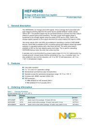
1 µF Film 0.1 µF Ceramic<br />
1A<br />
1B<br />
2A<br />
2B<br />
3A<br />
3B<br />
4A<br />
4B<br />
1<br />
2<br />
3<br />
4<br />
5<br />
6<br />
8<br />
9<br />
V DD<br />
7<br />
14<br />
V OUT<br />
470 pF<br />
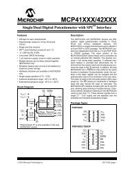
FIGURE 4-1: Switching Time Test Circuit.<br />
13<br />
12<br />
11<br />
10<br />
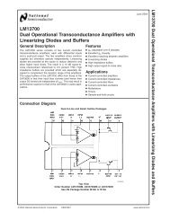
+5 V<br />
Input<br />
(A, B)<br />
0V<br />
V DD<br />
Output<br />
0V<br />
EQUATION<br />
Package power dissipation is the sum of load,<br />
quiescent and transition power dissipations. An<br />
example shows the relative magnitude for each term:<br />
Maximum operating temperature is:<br />
EQUATION<br />
PT fVs 10 10 9 –<br />
= ( × )<br />
C = 1000 pF Capacitive Load<br />
VS = 15 V<br />
D = 50%<br />
f = 200 kHz<br />
Note: Ambient operating temperature should not<br />
exceed +85°C for "EJD" device or +125°C<br />
for "MJD" device.<br />
DS21425B-page 10 © 2002 <strong>Microchip</strong> Technology Inc.<br />
10%<br />
P D<br />
= Package Power Dissipation<br />
= PL + PQ + PT = 45mW + 35mW + 30mW<br />
= 110mW<br />
TJ – θJA( PD) = 141°C<br />
TJ = Maximum allowable junction temperature<br />
(+150°C )<br />
θJA = Junction-to-ambient thernal resistance<br />
(83.3°C/W) 14-pin plastic package<br />
Input: 100 kHz,<br />
square wave,<br />
t RISE = t FALL ≤ 10 nsec<br />
90%<br />
tD1 t R<br />
90%<br />
t D2<br />
10% 10%<br />
90%<br />
t F