I/O Devices and disk scheduling - Csbdu.in
I/O Devices and disk scheduling - Csbdu.in
I/O Devices and disk scheduling - Csbdu.in
You also want an ePaper? Increase the reach of your titles
YUMPU automatically turns print PDFs into web optimized ePapers that Google loves.
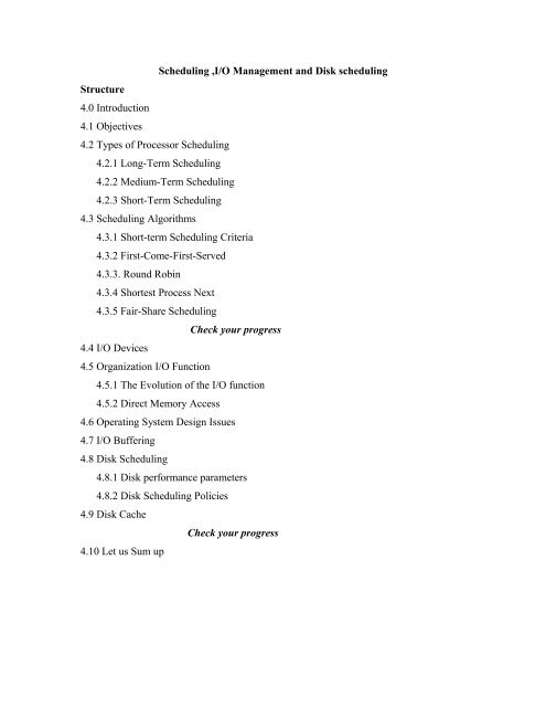
Structure<br />
4.0 Introduction<br />
4.1 Objectives<br />
4.2 Types of Processor Schedul<strong>in</strong>g<br />
Schedul<strong>in</strong>g ,I/O Management <strong>and</strong> Disk <strong>schedul<strong>in</strong>g</strong><br />
4.2.1 Long-Term Schedul<strong>in</strong>g<br />
4.2.2 Medium-Term Schedul<strong>in</strong>g<br />
4.2.3 Short-Term Schedul<strong>in</strong>g<br />
4.3 Schedul<strong>in</strong>g Algorithms<br />
4.3.1 Short-term Schedul<strong>in</strong>g Criteria<br />
4.3.2 First-Come-First-Served<br />
4.3.3. Round Rob<strong>in</strong><br />
4.3.4 Shortest Process Next<br />
4.3.5 Fair-Share Schedul<strong>in</strong>g<br />
4.4 I/O <strong>Devices</strong><br />
4.5 Organization I/O Function<br />
Check your progress<br />
4.5.1 The Evolution of the I/O function<br />
4.5.2 Direct Memory Access<br />
4.6 Operat<strong>in</strong>g System Design Issues<br />
4.7 I/O Buffer<strong>in</strong>g<br />
4.8 Disk Schedul<strong>in</strong>g<br />
4.8.1 Disk performance parameters<br />
4.8.2 Disk Schedul<strong>in</strong>g Policies<br />
4.9 Disk Cache<br />
4.10 Let us Sum up<br />
Check your progress
4.0 Introduction<br />
The first half of this unit beg<strong>in</strong>s with an exam<strong>in</strong>ation of types of processor <strong>schedul<strong>in</strong>g</strong><br />
show<strong>in</strong>g the way <strong>in</strong> which they are related. We will see how short-term <strong>schedul<strong>in</strong>g</strong> is<br />
used on a s<strong>in</strong>gle processor system <strong>and</strong> discuss the various Schedul<strong>in</strong>g algorithms. The<br />
next part of this unit focuses on discussion of I/O devices, Organization of I/O functions,<br />
Operat<strong>in</strong>g design issues, the way <strong>in</strong> I/O function can be structured <strong>and</strong> also we will<br />
exam<strong>in</strong>e the different <strong>disk</strong> <strong>schedul<strong>in</strong>g</strong> algorithms.<br />
4.1 Objectives<br />
At the end of this unit you will be able to<br />
• Identify the various external devices that are used <strong>in</strong> I/O<br />
• Discuss the various techniques for perform<strong>in</strong>g I/O<br />
• Expla<strong>in</strong> the concept of DMA<br />
• List the various design issues of Operat<strong>in</strong>g System<br />
• Describe the various I/O buffer<strong>in</strong>g<br />
• Expla<strong>in</strong> the work<strong>in</strong>g of Disk Schedul<strong>in</strong>g<br />
• Capture the concept of Disk Cache.<br />
4.2Types of Processor Schedul<strong>in</strong>g<br />
The aim of processor <strong>schedul<strong>in</strong>g</strong> is to assign processes to be executed by the<br />
processor of processors over time, <strong>in</strong> a way that meets system objectives, such as<br />
response, throughput, <strong>and</strong> processor efficiency. Schedul<strong>in</strong>g activities can be divided <strong>in</strong>to<br />
three functions Long-term, Medium term <strong>and</strong> Short term <strong>schedul<strong>in</strong>g</strong>.
Long-term<br />
Schedul<strong>in</strong>g Long-term <strong>schedul<strong>in</strong>g</strong><br />
Ready/<br />
Suspen<br />
d<br />
Blocked<br />
/<br />
Suspen<br />
d<br />
New<br />
Runn<strong>in</strong><br />
Ready<br />
g<br />
Medium-term Short-term <strong>schedul<strong>in</strong>g</strong><br />
Schedul<strong>in</strong>g<br />
4.2.1 Long term <strong>schedul<strong>in</strong>g</strong><br />
Figure 4.1 Schedul<strong>in</strong>g <strong>and</strong> Process State Transitions<br />
Long term <strong>schedul<strong>in</strong>g</strong> is performed when a new process is created. This is the<br />
decision to add a new process to the set of processes that are currently active. It controls<br />
the degree of multiprogramm<strong>in</strong>g. In a batch system, or for the batch portion of a general-<br />
purpose operat<strong>in</strong>g system, newly submitted jobs are routed to <strong>disk</strong> <strong>and</strong> held <strong>in</strong> batch<br />
queue. The long-term scheduler creates processes from the queue when it can. There are<br />
two decisions <strong>in</strong>volved here. First, the scheduler must decide that the operat<strong>in</strong>g system<br />
can take on one or more additional processes. Second, the scheduler must decide which<br />
job or jobs to accept <strong>and</strong> turn <strong>in</strong>to processes. Each tune job term<strong>in</strong>ates, the scheduler may<br />
make the decision to add one or more new jobs. The decision as to which job to admit<br />
next can be on a simple first-come-first-served basis.<br />
4.2.2 Medium-Term Schedul<strong>in</strong>g<br />
Blocked<br />
Exit
It is a part of the swapp<strong>in</strong>g function. The decision to add the number of processes<br />
that are partially or fully <strong>in</strong> ma<strong>in</strong> memory. Typically, the swapp<strong>in</strong>g-<strong>in</strong> decision is based<br />
on the need to manage the degree of multiprogramm<strong>in</strong>g. The swapp<strong>in</strong>g-<strong>in</strong> decision will<br />
consider the memory requirements of the swapped-out processes also.<br />
4.2.3 Short-Term Schedul<strong>in</strong>g<br />
Short-term <strong>schedul<strong>in</strong>g</strong> is the actual decision of which ready process to execute<br />
next. It is <strong>in</strong>voked whenever an even occurs that may lead to the suspension of the current<br />
process or that may provide an opportunity to preempt a currently runn<strong>in</strong>g process <strong>in</strong><br />
favor of another. Eg. Clock <strong>in</strong>terrupts, I/O <strong>in</strong>terrupts, Operat<strong>in</strong>g system calls, Signals.<br />
4.3 Schedul<strong>in</strong>g algorithms<br />
4.3.1 Short term <strong>schedul<strong>in</strong>g</strong> Criteria<br />
• User Oriented, Performance Related<br />
The ma<strong>in</strong> objective of short-term <strong>schedul<strong>in</strong>g</strong> is to allocate processor time <strong>in</strong> such<br />
a way to optimize one or more aspects of behavior. The commonly used criteria can be<br />
categorized along two dimensions: User oriented criteria <strong>and</strong> system oriented criteria.<br />
• User oriented, Performance related<br />
Turnaround time: This is the <strong>in</strong>terval of time between the submission of a process <strong>and</strong> its<br />
completion. Includes actual execution time plus time spent wait<strong>in</strong>g for resources,<br />
<strong>in</strong>clud<strong>in</strong>g the processor. This is an appropriate measure for a batch job.<br />
Response time: For <strong>and</strong> <strong>in</strong>teractive process, this is the time from the submission of a<br />
request until the response beg<strong>in</strong>s to be received. Often a process can beg<strong>in</strong> produc<strong>in</strong>g<br />
some output to the user while cont<strong>in</strong>u<strong>in</strong>g to process the request. Thus, this is better<br />
measure than turnaround time from the user’s po<strong>in</strong>t of view. The <strong>schedul<strong>in</strong>g</strong> discipl<strong>in</strong>e<br />
should attempt to achieve low response time <strong>and</strong> to maximize the number of <strong>in</strong>teractive<br />
users receiv<strong>in</strong>g acceptable response time.<br />
Deadl<strong>in</strong>es: When process completion deadl<strong>in</strong>e can be specified, the <strong>schedul<strong>in</strong>g</strong><br />
discipl<strong>in</strong>e should subord<strong>in</strong>ate other goals to that of maximiz<strong>in</strong>g the percentage of<br />
deadl<strong>in</strong>es met.<br />
• User Oriented, Other
Predictability: A given job should the same amount of time <strong>and</strong> at about the same<br />
cost regardless of the load on the system. A wide variation <strong>in</strong> response time or turnaround<br />
time is distract<strong>in</strong>g to users. It may signal a wide sw<strong>in</strong>g <strong>in</strong> system workloads or the need<br />
for system tun<strong>in</strong>g to cure <strong>in</strong>stabilities<br />
• System Oriented, Performance Related<br />
Throughput: The <strong>schedul<strong>in</strong>g</strong> policy should attempt to maximize the number of<br />
processes completed per unit of time. This is a measure of how much work is be<strong>in</strong>g<br />
performed. This clearly depends on the average length of a process but is also <strong>in</strong>fluenced<br />
by the <strong>schedul<strong>in</strong>g</strong> policy, which may affect utilization.<br />
Processor utilization: This is the percentage of time that the processor is busy. For<br />
an expensive shared system, this is a significant criterion. In s<strong>in</strong>gle-user systems <strong>and</strong> <strong>in</strong><br />
some other systems, such as real-time systems, this criterion is less important than some<br />
of the others.<br />
• System oriented, other<br />
Fairness: In the absence of guidance from the user or other system-supplied<br />
guidance, processes should be treated the same <strong>and</strong> no process should suffer<br />
starvation<br />
Enforc<strong>in</strong>g priorities: When processes are assigned priorities, the <strong>schedul<strong>in</strong>g</strong><br />
policy should favor higher priority processes.<br />
Balanc<strong>in</strong>g resources: The <strong>schedul<strong>in</strong>g</strong> policy should keep the resources of the<br />
system busy. Processes that will underutilize stressed resources should be favored. This<br />
criterion also <strong>in</strong>volves medium-term <strong>and</strong> long-term <strong>schedul<strong>in</strong>g</strong>.<br />
There are several <strong>schedul<strong>in</strong>g</strong> policies. The selection function determ<strong>in</strong>es which<br />
process, among ready processes, is selected next for execution. The function may be<br />
based on priority, resource requirements, or the execution characteristics of the process.<br />
In the latter case, three quantities are specialized.<br />
w = time spent <strong>in</strong> system so far, wait<strong>in</strong>g <strong>and</strong> execut<strong>in</strong>g<br />
e = time spent <strong>in</strong> execution so far<br />
s = total service time required by the process, <strong>in</strong>clud<strong>in</strong>g e, generally, this quantity must be<br />
estimated or supplied by the user<br />
Eg. The selection function max[w] <strong>in</strong>dicates a first-come-first-served.
The decision mode specifies the <strong>in</strong>stants <strong>in</strong> time at which the selection function is<br />
exercised. There two general categories:<br />
• Nonpreemptive : In this case, once a process is <strong>in</strong> the runn<strong>in</strong>g state, it cont<strong>in</strong>ues to<br />
execute until it term<strong>in</strong>ates or blocks itself to wait for I/O or to request some<br />
operat<strong>in</strong>g system service<br />
• Preemptive: The currently runn<strong>in</strong>g process may be <strong>in</strong>terrupted <strong>and</strong> moved to the<br />
Ready state by the operat<strong>in</strong>g system. The decision to preempt may be performed<br />
when a new process arrives, when an <strong>in</strong>terrupt occurs that places blocked process<br />
<strong>in</strong> the Ready stat, or periodically based on a clock <strong>in</strong>terrupt.<br />
4.3.2 First-come-First-Served<br />
Process Arrival Time Service Time<br />
A 0 3<br />
B 2 6<br />
C 4 4<br />
D 6 5<br />
E 8 2<br />
Figure 4.2 Process <strong>schedul<strong>in</strong>g</strong><br />
The simplest <strong>schedul<strong>in</strong>g</strong> policy is first-come-first-served (FCFS), also known as<br />
first-<strong>in</strong>-first-out (FIFO) or a strict queue scheme. As each process becomes ready, it jo<strong>in</strong>s<br />
the ready queue. When the currently runn<strong>in</strong>g process f<strong>in</strong>ished execution the process that<br />
has been <strong>in</strong> the ready queue the longest is selected.<br />
In terms of the queu<strong>in</strong>g model, Turn Around Time (TAT) is the residence time Tr,<br />
or total time that the item spends <strong>in</strong> the system. (Wait<strong>in</strong>g time plus service time).The<br />
normalized turnaround time, which is the ratio of turnaround time to service time. This<br />
value <strong>in</strong>dicates the relative delay experienced by a process. Typically, the longer the<br />
process execution time, the greater the absolute amount of delay that can be tolerated.<br />
The m<strong>in</strong>imum possible value for this ratio is 1.0 <strong>in</strong>creas<strong>in</strong>g values correspond to a
decreas<strong>in</strong>g level of service. FCFS performs much better for long processes than short<br />
ones <strong>and</strong> it favor processor-bound processes over I/O bound processes.<br />
4.3.3 Round Rob<strong>in</strong><br />
A straightforward way to reduce the penalty that short jobs suffer with FCFS is to<br />
use preemption based on a clock. The simplest such policy is round rob<strong>in</strong>. A clock<br />
<strong>in</strong>terrupt is generated at periodic <strong>in</strong>tervals. When the <strong>in</strong>terrupt occurs, the currently<br />
runn<strong>in</strong>g process is placed <strong>in</strong> the ready queue, <strong>and</strong> the next ready job is selected on a<br />
FCFS Basis. This technique is also known as time slic<strong>in</strong>g, because each process is given a<br />
slice of time before be<strong>in</strong>g preempted.<br />
With round rob<strong>in</strong>, the pr<strong>in</strong>cipal design issue is the length of the time quantum, or<br />
slice, to be used. If the quantum is very short, then short processes will move through the<br />
system relatively quickly. On the other h<strong>and</strong>, there is process<strong>in</strong>g overhead <strong>in</strong>volved <strong>in</strong><br />
h<strong>and</strong>l<strong>in</strong>g the clock <strong>in</strong>terrupt <strong>and</strong> perform<strong>in</strong>g the <strong>schedul<strong>in</strong>g</strong> <strong>and</strong> dispatch<strong>in</strong>g function.<br />
Thus, very short time quantum should be avoided.<br />
Round rob<strong>in</strong> is particularly effective <strong>in</strong> a general-purpose time-shar<strong>in</strong>g system or<br />
transaction process<strong>in</strong>g system. One drawback to round rob<strong>in</strong> is its relative treatment of<br />
processor-bound <strong>and</strong> I/O bound processes. I/O-bound process has a shorter processor<br />
Burst than a processor-bound process.<br />
Time-out
Admit Ready Queue Dispatch Release<br />
Processor<br />
Auxiliary queue<br />
I/O 1 queue<br />
I/O 2 queue<br />
I/O n queue<br />
I/O 1 wait<br />
I/O 2 wait<br />
I/O n wait<br />
Figure 4.3 Queu<strong>in</strong>g Diagram for Virtual Round-Rob<strong>in</strong> Scheduler<br />
4.3.4 Shortest Process Next<br />
The Shortest Process Next (SPN) policy is a nonpreemptive policy <strong>in</strong> which the<br />
process with the shortest expected process<strong>in</strong>g time is selected next. Thus a short process<br />
will jump to the head of the queue past longer jobs. One difficulty with the SPN policy is<br />
the need to know or at least estimate the required process<strong>in</strong>g time of each process. For<br />
batch jobs, the system may require the programmer to estimate the value <strong>and</strong> supply it to<br />
the operat<strong>in</strong>g system. If the programmer’s estimate is substantially under the actual<br />
runn<strong>in</strong>g time, the may abort the job. The simple calculation would be:<br />
n
Where<br />
Sn+1 =1/n ΣTi<br />
Ti = processor execution time for the i th <strong>in</strong>stance of this process<br />
S = Predicated value for the ith <strong>in</strong>stance<br />
S1 = predicated value for first <strong>in</strong>stance; not calculated<br />
4.3.5 Fair-Share Schedul<strong>in</strong>g<br />
All of the <strong>schedul<strong>in</strong>g</strong> algorithms discussed so far treat the collection of ready<br />
processes as a s<strong>in</strong>gle pool of processes from which to select the next runn<strong>in</strong>g process.<br />
However, <strong>in</strong> a multi-user system, if <strong>in</strong>dividual user applications or jobs may be organized<br />
as multiple processes, then there is a structure to the collection of processes that is not<br />
recognized by traditional scheduler. In fair-share <strong>schedul<strong>in</strong>g</strong>, the <strong>schedul<strong>in</strong>g</strong> decisions<br />
made based on how a set of processes performs<br />
Check your progress<br />
1. Def<strong>in</strong>e <strong>schedul<strong>in</strong>g</strong>.<br />
2. Describe Long term <strong>schedul<strong>in</strong>g</strong>.<br />
3. Give two examples for short term <strong>schedul<strong>in</strong>g</strong>.<br />
4. What is nonpreemptive process?<br />
5. Mention the two type decision modes.<br />
6. Exp<strong>and</strong> FCFS.<br />
7. What is turnaround time?<br />
8. List various <strong>schedul<strong>in</strong>g</strong> policies.<br />
9. Def<strong>in</strong>e round rob<strong>in</strong>.<br />
10. What is the difficulty <strong>in</strong> SPN policy?<br />
11. Describe Fair-Share Schedul<strong>in</strong>g.<br />
I/O <strong>Devices</strong> <strong>and</strong> <strong>disk</strong> <strong>schedul<strong>in</strong>g</strong><br />
4.4. I/O <strong>Devices</strong><br />
External <strong>Devices</strong> that are used <strong>in</strong> I/O with computer systems can be roughly grouped <strong>in</strong>to<br />
three classes<br />
i=1
• Human readable: Suitable for communicat<strong>in</strong>g with the computer user. Eg.Display,<br />
Keyboard, <strong>and</strong> perhaps other devices such as mouse<br />
• Mach<strong>in</strong>e Readable: Suitable for communication with electronic equipment Eg.<br />
<strong>disk</strong> ,tape drives, sensors, controllers, <strong>and</strong> actuators<br />
• Communication: Suitable for communication with remote devices. Eg. Digital<br />
l<strong>in</strong>e drivers <strong>and</strong> modems.<br />
There are great differences across these classes are<br />
• Data rate : There may be differences <strong>in</strong> data transfer rate<br />
• Application: The use of the device on the software <strong>and</strong> policies <strong>in</strong> the operat<strong>in</strong>g<br />
system <strong>and</strong> support<strong>in</strong>g utilities.<br />
For eg. A <strong>disk</strong> used for files requires the support of file management.<br />
• Complexity of control: A pr<strong>in</strong>ter requires a relatively simple control <strong>in</strong>terface.<br />
A <strong>disk</strong> is much more complex.<br />
• Unit of transfer : Data may transferred as a stream of bytes or<br />
characters(eg.term<strong>in</strong>al I/O) or <strong>in</strong> larger blocks(e.g <strong>disk</strong> I/O)<br />
• Data representation : Different data encod<strong>in</strong>g schemes are used by different<br />
device, <strong>in</strong>clud<strong>in</strong>g differences <strong>in</strong> character code <strong>and</strong> parity conventions<br />
• Error conditions : The nature errors, the way <strong>in</strong> which they are reported, their<br />
consequences, <strong>and</strong> the available range of responses differ widely from one device<br />
to another<br />
4.5 Organization of the I/0 functions<br />
Programmed I/O: The processor issues <strong>and</strong> I/O comm<strong>and</strong>, on behalf of a process, to<br />
<strong>and</strong> I/O module; that process then busy waits for the operation to be completed before<br />
proceed<strong>in</strong>g.<br />
Interrupt-driven I/O: The processor issues an I/O comm<strong>and</strong> on behalf of a process.<br />
After that the processor cont<strong>in</strong>ues to execute subsequent <strong>in</strong>structions <strong>and</strong> is<br />
<strong>in</strong>terrupted by I/O module when the latter has completed its work. The subsequent<br />
<strong>in</strong>structions may be <strong>in</strong> the same process, if it is not necessary for that process to wait<br />
for the completion of the I/O.
Direct memory access: A DMA module controls the exchange of data between ma<strong>in</strong><br />
memory <strong>and</strong> an I/O module.<br />
4.5.1 The Evolution of the I/O Function<br />
The evolutionary steps of I/O are<br />
1. The processor controls a peripheral device. This is seen <strong>in</strong> simple microprocessor-<br />
controlled device.<br />
2. A controller or I/O module is added. The processor uses programmed I/O without<br />
<strong>in</strong>terrupts.<br />
3. The same configuration as step 2 is used, but now <strong>in</strong>terrupts are employed. The<br />
processor need not spend time wait<strong>in</strong>g for an I/O operation to be performed, thus<br />
<strong>in</strong>creas<strong>in</strong>g efficiency<br />
4. The I/O module is given direct control of memory view DMA. I t can now more a<br />
block of data to or from memory without <strong>in</strong>volv<strong>in</strong>g the processor, except at the<br />
beg<strong>in</strong>n<strong>in</strong>g <strong>and</strong> end of the transfer<br />
5. The I/O module is enhanced to become a separate processor, with a specialized<br />
<strong>in</strong>struction. The CPU directs the I/O processor to execute program <strong>in</strong> ma<strong>in</strong> memory.<br />
The I/O processor to execute theses <strong>in</strong>structions without processor <strong>in</strong>tervention.<br />
6. The I/O module has a local memory is its own <strong>and</strong> is, <strong>in</strong> fact, a computer <strong>in</strong> its own<br />
right. With this architecture, a large set of I/O devices can be controlled with m<strong>in</strong>imal<br />
processor <strong>in</strong>volvement. A common use for such architecture has been to control<br />
communications with <strong>in</strong>teractive term<strong>in</strong>als. The I/O processor takes care most of the<br />
tasks <strong>in</strong>volved <strong>in</strong> controll<strong>in</strong>g the term<strong>in</strong>als.<br />
For all of the modules described <strong>in</strong> steps 4 through steps 6, the term direct<br />
memory access is appropriate, because all of these types <strong>in</strong>volve direct control of ma<strong>in</strong><br />
memory by the I/O module. Also, the I/O module <strong>in</strong> step 5 often referred to as an I/O<br />
channel <strong>and</strong> that <strong>in</strong> step 6 as an I/O processor<br />
4.5.2 Direct Memory Access<br />
The DMA module controls the exchange of data between ma<strong>in</strong> memory <strong>and</strong> an<br />
I/O module. It needs system bus to do this. The DMA module must use the bus only
when the processor does not need it, or it must force the processor to suspend operation<br />
temporarily. The latter technique is more common <strong>and</strong> is referred to as cycle steal<strong>in</strong>g,<br />
because the DMA unit <strong>in</strong> effect steals a bus cycle.<br />
Data count<br />
Data Register<br />
Address<br />
Register<br />
Control Logic<br />
The DMA technique works as follows.<br />
Figure 4.4 DMA Controller<br />
Data l<strong>in</strong>es<br />
Address l<strong>in</strong>es<br />
DMA request<br />
DMA acknowledge<br />
Interrupt<br />
rEAD Read<br />
Write<br />
• Whether a read or write is requested, us<strong>in</strong>g read or write control l<strong>in</strong>e between the<br />
processor <strong>and</strong> the DMA module<br />
• The address of the I/O device <strong>in</strong>volved, communicated on the data l<strong>in</strong>es<br />
• The start<strong>in</strong>g location <strong>in</strong> memory to read from or write to, communicated on the<br />
data l<strong>in</strong>es <strong>and</strong> stored by the DMA module <strong>in</strong> its address register<br />
• The number of words to be read or written, aga<strong>in</strong> communicated via the data l<strong>in</strong>es<br />
<strong>and</strong> stored <strong>in</strong> the data count register<br />
The Processor then cont<strong>in</strong>ues with other work. It has assigned this I/O operation<br />
to DMA module. The DMA module transfers the entire block of data, one word at a<br />
time, directly to or from memory, without go<strong>in</strong>g through the processor. When the
transfer is complete, the DMA module sends an <strong>in</strong>terrupt signal to the processor.<br />
Thus, the processor is <strong>in</strong>volved only at the beg<strong>in</strong>n<strong>in</strong>g <strong>and</strong> end of the transfer.<br />
The DMA mechanism can be <strong>in</strong> different ways. Some possibilities are shown <strong>in</strong><br />
figure.<br />
Processor<br />
4.6 Operat<strong>in</strong>g system Design Issues<br />
Design Objectives<br />
DMA<br />
Processor DMA<br />
…<br />
(a) S<strong>in</strong>gle bus, detached DMA<br />
I/O<br />
I/O I/O Memory<br />
DMA<br />
I/O I/O<br />
(b). S<strong>in</strong>gle bus, <strong>in</strong>tegrated DMA-I/O<br />
Figure 4.5 Alternative DMA Configurations<br />
Two ma<strong>in</strong> objectives <strong>in</strong> design<strong>in</strong>g the I/O facility: Efficiency <strong>and</strong> generality.<br />
Efficiency is important because I/O operation often form a problem <strong>in</strong> a comput<strong>in</strong>g<br />
system. One way to tackle this problem <strong>in</strong> multiprogramm<strong>in</strong>g, allows some processes to<br />
be wait<strong>in</strong>g on I/O operations while another process is execut<strong>in</strong>g. Thus, a major effort on<br />
I/O design has been schemes for improv<strong>in</strong>g the efficiency of the I/O.<br />
Memory<br />
The other major objective is generality. In the <strong>in</strong>terests of simplicity <strong>and</strong> freedom<br />
from error, it is desirable to h<strong>and</strong>le all devices <strong>in</strong> a uniform manner. Because of diversity
of device characteristics, it is difficult <strong>in</strong> practice to achieve true generality. What can be<br />
done is to use a hierarchical, modular approach to the design of the I/O.<br />
Logical structure of the I/O function<br />
The local peripheral device communicates <strong>in</strong> a simple fashion, such as a stream<br />
of bytes or records. The important layers are:<br />
• Logical I/O: The logical I/O module deals with device as a logical resource. This<br />
module is concerned with manag<strong>in</strong>g general I/O functions on behalf of user<br />
processes. It deals the device <strong>in</strong> terms of simple comm<strong>and</strong>s such as open, close,<br />
read, write.<br />
• Device I/O: The requested operations <strong>and</strong> data are converted <strong>in</strong>to appropriate<br />
sequences of I/O <strong>in</strong>structions, channel comm<strong>and</strong>s. And controller orders.<br />
Buffer<strong>in</strong>g techniques may be used to improve utilization.<br />
• Schedul<strong>in</strong>g <strong>and</strong> control : The actual queu<strong>in</strong>g <strong>and</strong> <strong>schedul<strong>in</strong>g</strong> of I/O operations<br />
Occurs at this layer, as well as the control of the operations. Thus, <strong>in</strong>terrupts are<br />
h<strong>and</strong>led at this layer <strong>and</strong> I/O status is collected <strong>and</strong> reported. This is the layer of<br />
software that actually <strong>in</strong>teracts with the I/O module <strong>and</strong> hence the device<br />
hardware.<br />
The next structure is communication port looks much the same as the first case. The Only<br />
difference is that the logical I/O module is replaced by communications architecture. The<br />
last one is File system. The layers are<br />
• Directory management: At this layer, symbolic file names are converted to<br />
identifiers. The identifiers either reference the file directly or <strong>in</strong>directly through a<br />
file descriptor or <strong>in</strong>dex table.<br />
• File system: This layer deals with the logical structure of files <strong>and</strong> with the<br />
operations that can be specified by users, such as open, close, read, write.<br />
Access rights are also managed at this layer.<br />
• Physical organization: In segmentation <strong>and</strong> pag<strong>in</strong>g structure, logical references to<br />
files <strong>and</strong> records must be converted to physical secondary storage addresses,<br />
tak<strong>in</strong>g <strong>in</strong>to account the physical track <strong>and</strong> sector structure of the secondary
storage device. Allocation of secondary storage space <strong>and</strong> ma<strong>in</strong> storage buffers is<br />
treated <strong>in</strong> this layer.<br />
4.7 I/O Buffer<strong>in</strong>g<br />
There is a speed mismatch between I/O devices <strong>and</strong> CPU. This leads to<br />
<strong>in</strong>efficiency <strong>in</strong> processes be<strong>in</strong>g completed. To <strong>in</strong>crease the efficiency, it may be<br />
convenient to perform <strong>in</strong>put transfers <strong>in</strong> advance of requests be<strong>in</strong>g made <strong>and</strong> to<br />
perform output transfers some time after the request is made. This technique is known<br />
as buffer<strong>in</strong>g.<br />
In discuss<strong>in</strong>g the various approaches to buffer<strong>in</strong>g, it is sometimes important to<br />
make a dist<strong>in</strong>ction between two types of I/O devices:<br />
• Block-oriented <strong>Devices</strong> stores <strong>in</strong>formation <strong>in</strong> blocks that are usually of fixed size<br />
<strong>and</strong> transfers are made one block at a time. Eg.Disk,tape<br />
• Stream-oriented devices transfer data <strong>in</strong> <strong>and</strong> out as a stream of bytes, with no<br />
block structure. Eg. Term<strong>in</strong>als, pr<strong>in</strong>ters, communications port, mouse.<br />
S<strong>in</strong>gle Buffer<br />
The simplest type of buffer<strong>in</strong>g is s<strong>in</strong>gle buffer<strong>in</strong>g. When a user process issues <strong>and</strong><br />
I/O request, the operat<strong>in</strong>g system assigns a buffer <strong>in</strong> the system portion of ma<strong>in</strong><br />
memory to the operation. For block-oriented devices, the s<strong>in</strong>gle buffer<strong>in</strong>g scheme can<br />
be described as follows: Input transfers are made to the system buffer. When the<br />
transfer is complete, the process moves the block <strong>in</strong>to user space <strong>and</strong> immediately<br />
requests another block.<br />
I/O devices<br />
Operat<strong>in</strong>g System User Process<br />
In<br />
(a) No buffer<strong>in</strong>g<br />
Operat<strong>in</strong>g System User Process
I/O devices<br />
In Move<br />
(b) S<strong>in</strong>gle buffer<strong>in</strong>g<br />
Operat<strong>in</strong>g System User Process<br />
I/Odevice In Move<br />
(c)Double buffer<strong>in</strong>g<br />
Operat<strong>in</strong>g System User Process<br />
I/O device In Move<br />
. .<br />
(d) Circular Buffer<strong>in</strong>g<br />
Figure 4.6 I/O Buffer<strong>in</strong>g schemes<br />
For stream oriented I/O, the s<strong>in</strong>gle buffer<strong>in</strong>g scheme can be used <strong>in</strong> a l<strong>in</strong>e- at- a<br />
time Fashion or a byte-at-a-time fashion. In l<strong>in</strong>e-at-a-time fashion user <strong>in</strong>put <strong>and</strong><br />
output to the term<strong>in</strong>al is one l<strong>in</strong>e at a time. For eg. Scroll-mode term<strong>in</strong>als, l<strong>in</strong>e pr<strong>in</strong>ter.<br />
Suppose that T is the required to <strong>in</strong>put one block <strong>and</strong> that C is the computation time.<br />
Without buffer<strong>in</strong>g, the execution time per block is essentially T+C. With a s<strong>in</strong>gle<br />
buffer, the time is max[C, T] +M, Where M is the time required to move the data<br />
from the system buffer to user memory.
Double Buffer<br />
An improvement over s<strong>in</strong>gle buffer<strong>in</strong>g can be done by assign<strong>in</strong>g two system<br />
buffers to operation. A process now transfers data to one buffer while the operat<strong>in</strong>g<br />
system empties the other. This technique is known as double buffer<strong>in</strong>g or buffer<br />
swapp<strong>in</strong>g.<br />
For block-oriented transfer, we can roughly estimate the execution time as<br />
max[C,T].In both cases(CT) an improvement over s<strong>in</strong>gle buffer<strong>in</strong>g <strong>in</strong><br />
achieved. Aga<strong>in</strong>, this improvement comes at the cost of <strong>in</strong>creased complexity. For<br />
stream-oriented <strong>in</strong>put, there are two alternative modes operation. For l<strong>in</strong>e-at-a time<br />
I/O, the user process need not be suspended for <strong>in</strong>put or output, unless the process<br />
runs ahead of the double buffers. For byte-at-a time operation, the double buffer<br />
offers no particular advantage over a s<strong>in</strong>gle buffer of twice the length.<br />
Circular Buffer<strong>in</strong>g<br />
Double buffer<strong>in</strong>g may be <strong>in</strong>adequate if the process performs rapid bursts of I/O.<br />
In this case, the problem can be solved by us<strong>in</strong>g more than one buffer. When more<br />
than two buffers are used, the collection of buffers is itself referred to as a circular<br />
buffer.<br />
The utility of buffer<strong>in</strong>g<br />
Buffer<strong>in</strong>g is a technique that smooths out peaks <strong>in</strong> I/O dem<strong>and</strong>. However, no<br />
amount of buffer<strong>in</strong>g will allow an I/O device to keep pace with a process <strong>in</strong>def<strong>in</strong>itely<br />
when average dem<strong>and</strong> of the process is greater than the I/O device can service. Even<br />
with multiple buffers, all of the buffers will eventually fill up <strong>and</strong> the process will<br />
have to wait after process<strong>in</strong>g each chunk of data.<br />
4.8 Disk <strong>schedul<strong>in</strong>g</strong><br />
In this section, we highlight some of the key issues of the performance of <strong>disk</strong><br />
system.<br />
4.8.1Disk performance parameters
The actual details of <strong>disk</strong> I/O operation depend on the computer system, operat<strong>in</strong>g<br />
system <strong>and</strong> the nature of I/O channel <strong>and</strong> <strong>disk</strong> controller hardware. When the <strong>disk</strong><br />
drive is operat<strong>in</strong>g, the <strong>disk</strong> is rotat<strong>in</strong>g at constant speed. To read or write, the head<br />
must be positioned at the desired track <strong>and</strong> at the beg<strong>in</strong>n<strong>in</strong>g of desired sector on that<br />
track. Track can be selected us<strong>in</strong>g either mov<strong>in</strong>g-head or fixed-head. On a movable-<br />
head system, the time it takes to position the head at the track is known as seek time.<br />
In either case, once the track is selected, the <strong>disk</strong> controller waits until the appropriate<br />
sector reached. The time it takes to f<strong>in</strong>d the right sector is known as rotational delay<br />
or rotational latency. The sum of seek time, <strong>and</strong> the rotational delay is access time<br />
(the time taken to read or write).<br />
In addition to these times, there are several queu<strong>in</strong>g time associated with <strong>disk</strong><br />
operation. When a process issues an I/O request, it must first wait <strong>in</strong> a queue for the<br />
device to be available. At that time, the device is assigned to the process. If the device<br />
shares a s<strong>in</strong>gle I/O channel or a set of I/O channels with other <strong>disk</strong> drives, then there<br />
may be an additional wait for the channel to be available.<br />
Seek time<br />
Seek time is the time required to move the <strong>disk</strong> arm to the required track. The<br />
seek time consists of two key components: the <strong>in</strong>itial startup time, <strong>and</strong> the time taken<br />
to traverse the tracks. The traversal time is not a l<strong>in</strong>ear function of the number of<br />
tracks but <strong>in</strong>cludes a startup time <strong>and</strong> a settl<strong>in</strong>g time.<br />
Rotational delay<br />
Magnetic <strong>disk</strong>s, other than floppy <strong>disk</strong>s, have rotational speeds <strong>in</strong> the range 400 to<br />
10,000 rpm. Floppy <strong>disk</strong>s typically rotate at between 300 to 600rpm. Thus the average<br />
delay will be between 100 <strong>and</strong> 200 ms.<br />
Transfer Time<br />
The transfer time to or from the <strong>disk</strong> depends on the rotation speed of the <strong>disk</strong> <strong>in</strong> the<br />
follow<strong>in</strong>g fashion:<br />
Where<br />
T=b/rN<br />
T=transfer time<br />
B= number bytes to be transferred
N = number of bytes on a track<br />
R= rotation speed, <strong>in</strong> revolutions per second<br />
Thus the total average access time can be expressed as Ta=Ts+1/2r+b/rN<br />
Where Ts is the average seek time<br />
4.8.2.Disk Schedul<strong>in</strong>g Policies<br />
There are several <strong>disk</strong> <strong>schedul<strong>in</strong>g</strong> Policies with different seek time.<br />
R<strong>and</strong>om <strong>schedul<strong>in</strong>g</strong>: The requested track is selected r<strong>and</strong>omly.<br />
Next track<br />
accessed<br />
FIFO SSTF SCAN C-SCAN<br />
No.of<br />
tracks<br />
traversed<br />
Next track<br />
accessed<br />
No.of<br />
tracks<br />
traversed<br />
Next track<br />
accessed<br />
No.of<br />
tracks<br />
traversed<br />
Next track<br />
accessed<br />
No.of<br />
tracks<br />
traversed<br />
55 45 90 10 150 50 150 50<br />
58 3 58 32 160 10 160 10<br />
39 19 55 3 184 24 184 24<br />
18 21 39 16 90 94 90 164<br />
90 72 38 1 58 32 58 20<br />
160 70 18 20 55 3 55 1<br />
150 10 150 132 39 16 39 16<br />
38 112 160 10 38 1 38 3<br />
184 146 184 24 18 20 18 32<br />
Average<br />
seek<br />
55.3 Average<br />
seek<br />
27.5 Average<br />
seek<br />
27.8 Average<br />
seek<br />
35.8<br />
length<br />
length<br />
length<br />
length<br />
First –<strong>in</strong>-first out<br />
Figure 4.7 Comparison of Disk <strong>schedul<strong>in</strong>g</strong> algorithms<br />
The I/O requests are satisfied <strong>in</strong> the order <strong>in</strong> which they arrived.<br />
Eg. Assume a <strong>disk</strong> with 200 tracks <strong>and</strong> that the <strong>disk</strong> request queue has r<strong>and</strong>om requests<br />
<strong>in</strong> it. The requested tracks, <strong>in</strong> the order received, are 55, 58, 39, 18, 90, 160, 150, 38, 184.<br />
Priority<br />
With a system based on priority (PRI), the control of the <strong>schedul<strong>in</strong>g</strong> is outside the<br />
control of <strong>disk</strong> management. The short batch jobs <strong>and</strong> <strong>in</strong>teractive jobs are given higher<br />
priority than longer jobs that require longer computation. This type of policy tends to be<br />
poor for database systems.
Last <strong>in</strong> first out<br />
In this policy the most recent requests are given preference. In transaction<br />
process<strong>in</strong>g systems, giv<strong>in</strong>g the device to the most recent user should result <strong>in</strong> little or no<br />
arm movement for mov<strong>in</strong>g through a sequential file. FIFO, Priority, <strong>and</strong> LIFO <strong>schedul<strong>in</strong>g</strong><br />
are based solely on attributes of the queue or the requester.<br />
Shortest service time first<br />
The SSTF policy is to select the <strong>disk</strong> I/O request that requires the least movement<br />
of the <strong>disk</strong> arm from its current position. Thus, we always choose to <strong>in</strong>cur the m<strong>in</strong>imum<br />
seek time. This policy provides better performance than FIFO.<br />
SCAN<br />
With the exception of FIFO, all of the policies can leave some request unfulfilled<br />
until the entire queue is emptied. That is, there may always be new requests arriv<strong>in</strong>g that<br />
will be chosen before an exist<strong>in</strong>g request. With SCAN, the arm is required to move <strong>in</strong><br />
one direction only, satisfy<strong>in</strong>g all outst<strong>and</strong><strong>in</strong>g requests, until it reaches the last track <strong>in</strong> that<br />
direction or until there are no more requests <strong>in</strong> that direction.<br />
C-SCAN<br />
The C-SCAN (circular SCAN) policy restricts scann<strong>in</strong>g to one direction only.<br />
Thus, when the last track has been visited <strong>in</strong> one direction, the arm is returned to the<br />
opposite end of the <strong>disk</strong> <strong>and</strong> the scan beg<strong>in</strong>s aga<strong>in</strong>. This reduces the maximum delay<br />
experienced by new requests. With SCAN, if the expected time for a scan from <strong>in</strong>ner<br />
track to outer track is t, then the expected service <strong>in</strong>terval for sectors at the periphery is<br />
2t. With C-SCAN, the <strong>in</strong>terval is on the order of t + smax where smax is the maximum seek<br />
time.<br />
N-step-SCAN <strong>and</strong> FSCAN<br />
With SSTF, SCAN AND C-SCAN it is possible that the arm may not move for a<br />
considerable period of time. High-density <strong>disk</strong>s are more likely to be affected. By this<br />
characteristic than lower density <strong>disk</strong>s <strong>and</strong>/or <strong>disk</strong>s with only one or two surfaces. To<br />
avoid this “arm stick<strong>in</strong>ess” the <strong>disk</strong> request queue can be segmented, with one segment at<br />
a time be<strong>in</strong>g processed completely.<br />
The N-step-SCAN policy segments the <strong>disk</strong> request queue <strong>in</strong>to sub queues of<br />
length N. Subqueues are processed one at a time, SCAN. While a queue is be<strong>in</strong>g
processed, new requests must be added to some other queue. If Fewer than N requests are<br />
available at the end of a scan, then all of them are processed with the next scan. With<br />
large values of N, the performance of N-step-SCAN approaches that of SCAN; with a<br />
value of N=1, the FIFO policy is adopted.<br />
FSCAN is a policy that uses two sub queues. When a scan beg<strong>in</strong>s, all of the<br />
requests are <strong>in</strong> one of the queues, with the other empty. Dur<strong>in</strong>g the scan, all new requests<br />
are put <strong>in</strong>to the other queue. Thus service of new requests is deferred until all of the old<br />
requests have been processed.<br />
4.9 Disk Cache<br />
The term Cache memory is usually used to apply to memory that is smaller <strong>and</strong><br />
faster than ma<strong>in</strong> memory <strong>and</strong> that is <strong>in</strong>terposed between ma<strong>in</strong> memory <strong>and</strong> the processor.<br />
Such a cache memory reduces average memory access time by exploit<strong>in</strong>g the pr<strong>in</strong>ciple of<br />
locality.<br />
A <strong>disk</strong> cache is a buffer <strong>in</strong> ma<strong>in</strong> memory for <strong>disk</strong> sectors. The cache conta<strong>in</strong>s a<br />
copy of some of the sectors on the <strong>disk</strong>. When an I/O request is made for a particular<br />
sector, a check is made to determ<strong>in</strong>e if the sector is <strong>in</strong> the <strong>disk</strong> cache. If so, the request is<br />
satisfied via the cache. If not, the requested sector is read <strong>in</strong>to the <strong>disk</strong> cache from the<br />
<strong>disk</strong>. Because of the phenomenon of locality of reference, when a block of data is fetched<br />
<strong>in</strong>to the cache to satisfy a s<strong>in</strong>gle I/O request, it is likely that there will be future references<br />
to that same block.<br />
Design Considerations<br />
Several design issues are of <strong>in</strong>terest. First, when an I/O request is satisfied from<br />
the <strong>disk</strong> cache, the data <strong>in</strong> the <strong>disk</strong> cache must be delivered to request<strong>in</strong>g process. This<br />
can be done either by transferr<strong>in</strong>g the block of data from <strong>disk</strong> cache to user process or<br />
simply by us<strong>in</strong>g a shared memory capability <strong>and</strong> pass<strong>in</strong>g a po<strong>in</strong>ter to the appropriate slot<br />
<strong>in</strong> the <strong>disk</strong> cache. The latter approach saves the time of a memory-to-memory transfer<br />
<strong>and</strong> also<br />
A second design issue has to do with the replacement strategy. When a sector is<br />
brought <strong>in</strong>to the <strong>disk</strong> cache, one of the exist<strong>in</strong>g blocks must be replaced. For this<br />
replacement, the most commonly used algorithm is least recently used (LRU): Replace
that block that has been <strong>in</strong> the cache longest with no reference to it. Logically, the cache<br />
consists of a stack of blocks, with the most recently reference block on the top of the<br />
stack.<br />
Another possibility is least frequently used (LFU): Replace the block that is not<br />
frequently used. The LFU can be implemented by associat<strong>in</strong>g a counter with each block.<br />
When a block is brought <strong>in</strong>, it is assigned a count of 1; with each reference to the block,<br />
its count is <strong>in</strong>cremented by 1. When replacement required, the block with smallest count<br />
is selected. One problem of LFU is the effect of locality may actually cause the LFU<br />
algorithm to make poor replacement choices.<br />
is proposed.<br />
To overcome this difficulty, a technique known as frequency-based replacement<br />
New section Old section<br />
MRU LRU<br />
Re-reference;<br />
count unchanged Re-reference<br />
Miss(new block brought <strong>in</strong>)<br />
count :=1<br />
Count:=count+1<br />
(a) FIIFO<br />
New section Middle section Old section<br />
… … …<br />
(b)Use of three sections<br />
Figure 4.8 Frequency-based Replacement<br />
MRU<br />
First consider a simplified version, given figure 4.8 a. The blocks are organized <strong>in</strong> a<br />
stack, as with the LRU algorithm. A certa<strong>in</strong> portion of the top part of the stack is set aside<br />
as a new section. When there is cache hit, the referenced block is moved to the top of the<br />
LRU
stack. If the block was already <strong>in</strong> the new section, its reference count is not <strong>in</strong>cremented;<br />
otherwise <strong>in</strong>cremented by 1. Given a sufficiently large new section, this result <strong>in</strong> the<br />
reference counts for blocks that are repeatedly re-referenced with<strong>in</strong> a short <strong>in</strong>terval<br />
rema<strong>in</strong><strong>in</strong>g unchanged. On a miss, the block with the smallest reference count that is not<br />
<strong>in</strong> the new section is chosen for replacement; the least recently-used such block is chosen<br />
<strong>in</strong> the event of a tie.<br />
Check your progress<br />
1. What are the two design objectives of I/O?<br />
2. Def<strong>in</strong>e buffer<strong>in</strong>g.<br />
3. Write the two types of I/O devices.<br />
4. Def<strong>in</strong>e buffer swapp<strong>in</strong>g.<br />
5. What is seek time?<br />
6. What is rotational delay?<br />
7. How will you calculate Transfer time?<br />
8. List out the <strong>disk</strong> <strong>schedul<strong>in</strong>g</strong> policies.<br />
9. Exp<strong>and</strong> SSTF.<br />
10. What is C-SCAN?<br />
11. Def<strong>in</strong>e Cache memory.<br />
12. Def<strong>in</strong>e LRU <strong>and</strong> LFU?<br />
4.10 Let us Sum up<br />
The operat<strong>in</strong>g system must make three types of <strong>schedul<strong>in</strong>g</strong> decisions with respect to the<br />
execution of process. Long term <strong>schedul<strong>in</strong>g</strong> determ<strong>in</strong>es when new processes are admitted<br />
to the system. Medium term <strong>schedul<strong>in</strong>g</strong> is part of the swapp<strong>in</strong>g function <strong>and</strong> determ<strong>in</strong>es<br />
when a program is bought partially or fully <strong>in</strong>to ma<strong>in</strong> memory so that it may be executed.<br />
Short term <strong>schedul<strong>in</strong>g</strong> determ<strong>in</strong>es which ready process will be executed next by the<br />
processor. A variety of algorithms has been used <strong>in</strong> short term <strong>schedul<strong>in</strong>g</strong> like First-<br />
Come, First-Served, Round Rob<strong>in</strong>, Shortest process next, Shortest rema<strong>in</strong><strong>in</strong>g time,<br />
Highest response ratio next <strong>and</strong> Feedback. The Choice of <strong>schedul<strong>in</strong>g</strong> algorithm depends<br />
on expected performance <strong>and</strong> on implementation complexity.
The computer system’s <strong>in</strong>terface to the outside world is its I/O architecture. The I/O<br />
architecture is designed to provide a systematic means of controll<strong>in</strong>g <strong>in</strong>formation <strong>and</strong> to<br />
provide operat<strong>in</strong>g system with the <strong>in</strong>formation it needs. The I/O function is broken <strong>in</strong>to<br />
number of layers, with lower layer deal<strong>in</strong>g with details closer to the physical functions to<br />
be performed, <strong>and</strong> higher layers deal<strong>in</strong>g with I/O <strong>in</strong> a logical <strong>and</strong> generic fashion. A key<br />
aspect of I/O is the use of buffer rather than application processes. Buffer<strong>in</strong>g smooth out<br />
the difference between the <strong>in</strong>ternal speeds of the computer system <strong>and</strong> speeds of the I/O<br />
device. Two of the approaches used to improve the <strong>disk</strong> I/O performance are Disk<br />
<strong>schedul<strong>in</strong>g</strong> <strong>and</strong> Disk Cache.


