Static and Dynamic Response of a Design of Differential ... - aerade
Static and Dynamic Response of a Design of Differential ... - aerade
Static and Dynamic Response of a Design of Differential ... - aerade
Create successful ePaper yourself
Turn your PDF publications into a flip-book with our unique Google optimized e-Paper software.
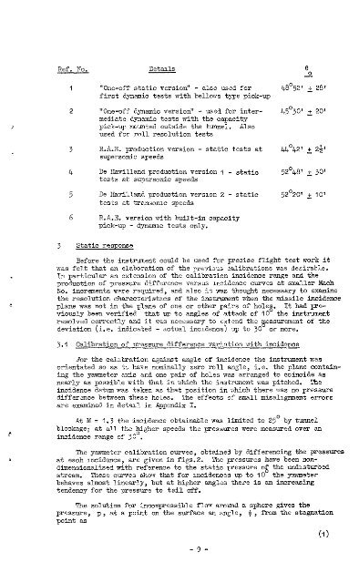
Ref. p,To.<br />
1<br />
2<br />
3<br />
4<br />
5<br />
6<br />
3 <strong>Static</strong> response<br />
Details<br />
"One-<strong>of</strong>f static version" - also used for<br />
first dynamic tests with belloivs type pick-up<br />
"One-<strong>of</strong>f dynamic version" - used for inter-<br />
mediate dynamic tests with the capacity<br />
pick-up mounted outside the tunnel. Also<br />
used for roll resolution tests<br />
R.&E. production version - static tests at<br />
supersonic speeds<br />
De Havill<strong>and</strong> production version I - statio<br />
tests at supersonic speeds<br />
De Havill<strong>and</strong> production version 2 - static<br />
tests at transomc speeds<br />
R.A.E. version with built-in capacity<br />
pick-up - dynamic tests only.<br />
e<br />
0<br />
4a052f + 28'<br />
45O301 + 20'<br />
44O42' + 241<br />
52'48' + 30'<br />
52'20' + 10'<br />
Before the instrument could be used for precise flight test work it<br />
was felt that an elaboration <strong>of</strong> the previous wlibrations was desirable.<br />
In particular an extension <strong>of</strong> the calibration incidence range <strong>and</strong> the<br />
production <strong>of</strong> pressure difference versus incidence curves at smaller Mach<br />
No. increments were required, <strong>and</strong> also it was thought necessary to examine<br />
the resolution characteristacs <strong>of</strong> the instrument when the missile incidence<br />
plane was not in the plane <strong>of</strong> one or other pairs <strong>of</strong> holeg. It had previously<br />
been verified that up to angles <strong>of</strong> attack <strong>of</strong> 10 the instrument<br />
resolved correctly <strong>and</strong> it ma s necessary to extend the measurement <strong>of</strong> the<br />
deviation (i.e. indicated - actual incidence) up to 30 or more.<br />
3.1 Calibration <strong>of</strong> pressure difference variation with incidence<br />
-<br />
?or the calibration against angle <strong>of</strong> incidence the instrument was<br />
orientated so as to have nominally zero roll angle, i.e. the plane contain-<br />
ing the yawmeter axis <strong>and</strong> one pair <strong>of</strong> holes was arranged to coincide as<br />
nearly as possible with that in rrhich the instrument was pitched. The<br />
incidence datum was taken as that position in -which there was no pressure<br />
difference between these holes. The effects <strong>of</strong> small misalignment errors<br />
are examined in detail in Appendix I.<br />
At M = 1.3 the incidence obtainable was limited to '25' by tunnel<br />
blockage; at all the $igher speeds the pressures were measured over an<br />
incidence range <strong>of</strong> 30 .<br />
The yawmeter calibration curves, obtained by differencing the pressures<br />
at each incidence, are given in figs.2. The pressures have been non-<br />
dimensionslised with reference to the static pressure 0% the undisturbed<br />
stream. These curves show that for incidences up to 10 the yawneter<br />
behaves almost linearly, but at higher angles there is


