Static and Dynamic Response of a Design of Differential ... - aerade
Static and Dynamic Response of a Design of Differential ... - aerade
Static and Dynamic Response of a Design of Differential ... - aerade
Create successful ePaper yourself
Turn your PDF publications into a flip-book with our unique Google optimized e-Paper software.
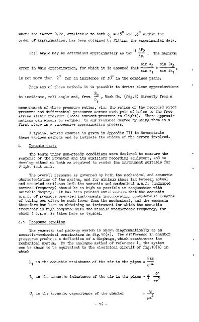
where the factor 0.22, applicable to both e. = 45' <strong>and</strong> 53' within the<br />
order <strong>of</strong> approximation, has been obtained by fitting the experimental data.<br />
Roll sngle mav be determined approximately as tar<br />
-, Al'2<br />
-. Themaximum<br />
API<br />
error in this approximation, for which it is assumed that<br />
sm<br />
sin<br />
a2<br />
a C<br />
1<br />
is not more than 2' for an incidence <strong>of</strong> 30' in the combined plane,<br />
sin 2a2<br />
sm 2~7, ' c<br />
From any <strong>of</strong> these methods it is possible to derive close approximations .<br />
to mncidence, roll angle <strong>and</strong>, from 22<br />
PS<br />
, Kach No. (fig.8) directly from a<br />
meas.rement <strong>of</strong> three pressure ratios, viz. the ratios <strong>of</strong> the recorded pitot<br />
pressure <strong>and</strong> differential pressures across each pair <strong>of</strong> holes to the free<br />
stream static pressure (local smbient pressure in flight), These approximations<br />
can always be refined to any required degree by using them as a<br />
first stage in a successive approximation process.<br />
A typical worked example is given in Appendix III to demonstrate<br />
these various methods <strong>and</strong> to indicate the orders <strong>of</strong> the errors involved.<br />
4<br />
DJ?namic tests<br />
'I"ne tests under non-steady conditions were designed to measure the T<br />
response <strong>of</strong> the yawmeter <strong>and</strong> its auxiliary recording equipment, <strong>and</strong> to<br />
develop either or both as required to render the instrument suitable for<br />
flight test work. -<br />
The overall response is governed by both the mechanical <strong>and</strong> acoustic<br />
characteristics <strong>of</strong> the system, <strong>and</strong> for minimum phase lag betiveen actual<br />
<strong>and</strong> recorded incidence both the acoustic <strong>and</strong> mechanical u.n.f. (undamped<br />
natural frequency) should be as high as possible in conjunction with<br />
suitable damping. It has been pointed outelse>&re that the acoustic<br />
u.n.f. <strong>of</strong> pressure operated instruments incorporating considerable lengths<br />
<strong>of</strong> tubing can <strong>of</strong>ten be much lamer than the mechanical, <strong>and</strong> the emphasis<br />
therefore has been on obtaining an instrument for which the acoustic<br />
frequency is high compssed with the missile weather-cock frequency, for<br />
which 3 c.p.s. is taken here as typical.<br />
4.1 iiesponse equation<br />
The yawmeter <strong>and</strong> pick-up system is shoprn diagranraatically as an<br />
acoustic-mechanical combination in fig.lO(a). The difference in chamber<br />
pressures produces a deflection <strong>of</strong> a dia&rsgm,which constitutes the<br />
mechanical system. By the analogue method <strong>of</strong> reference 1, the system<br />
can be shown to be equivalent to the electrical circuit <strong>of</strong> fig.lO(b) in<br />
which<br />
R, is the acoustic resistance <strong>of</strong> the air in the pipes = -<br />
xrk<br />
& 4?<br />
IL,, IS the acoustic inductance <strong>of</strong> the air in the pipes = 3<br />
2<br />
C, is the acoustic capacitance <strong>of</strong> the chamber<br />
- 16 -<br />
8871<br />
i


