Static and Dynamic Response of a Design of Differential ... - aerade
Static and Dynamic Response of a Design of Differential ... - aerade
Static and Dynamic Response of a Design of Differential ... - aerade
You also want an ePaper? Increase the reach of your titles
YUMPU automatically turns print PDFs into web optimized ePapers that Google loves.
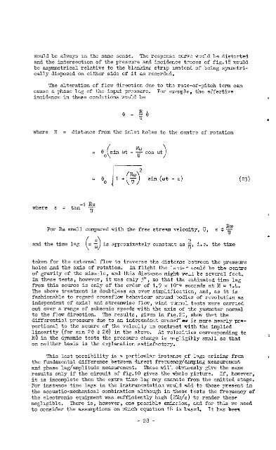
would be always m the same sense. The response curve nculd be distorted<br />
<strong>and</strong> the intersection <strong>of</strong> the pressure <strong>and</strong> incidence traces <strong>of</strong> fig.18 would<br />
be asymmetrical relative to the blanking strip instead <strong>of</strong> being symmetri-<br />
cally disposed on either side <strong>of</strong> it as recorded.<br />
'The alteration <strong>of</strong> flo-rl direction due to the rate-<strong>of</strong>-pitch term can<br />
cause a phase lag <strong>of</strong> the input pressure. For exmple, the effective<br />
incidence in these con&tions :rould be<br />
0 - tf3<br />
where R = distace from the inlet holes to the centre <strong>of</strong> rotation<br />
where E = tan<br />
-1 “u<br />
u<br />
= Oo,sin f cut - $ cos wt \<br />
\ /<br />
= e. ,++<br />
J 0<br />
2<br />
sin (ot - E)<br />
For Rw. small compared tith the free stream velocity, U, s .% T xw U<br />
<strong>and</strong> the time lag is approximatelj~<br />
R<br />
constat as - i.e. the time<br />
U'<br />
taken for the external flow to traverse the distame betATeen the pressure<br />
holesmd the axis <strong>of</strong> rotation. In flight the latter xould be the centre<br />
<strong>of</strong> gravity <strong>of</strong> the miszle, <strong>and</strong> this distance might well be several feet.<br />
In these tests, however,<br />
from this source is only<br />
it was only<br />
<strong>of</strong> the order<br />
3", so that the estimated time lag<br />
<strong>of</strong> 1.9 x IO-4 seconds at M = 1.4.<br />
The above treatment is doubtless<br />
fashionable to regard crossflow<br />
an over<br />
behaviow<br />
simplification,<br />
around bodies<br />
<strong>and</strong>, as it<br />
<strong>of</strong> revolutian<br />
is<br />
as<br />
independent <strong>of</strong> axial <strong>and</strong> streamwise flow,<br />
out over a range <strong>of</strong> subsonic speeds with<br />
wind. tunnel tests were carried<br />
the axis <strong>of</strong> the ,yawmeter normal<br />
to the flav<br />
differential<br />
direction.<br />
pressure<br />
The results , given<br />
due to an independent<br />
in flg.20,<br />
crossflew<br />
shw th?t the<br />
is mors nearly pr*rortiowl<br />
lineilrity<br />
R6 in the<br />
to the square <strong>of</strong> the velocity xn contrast with<br />
(for sin 20 T' 20) in the above. At velocities<br />
dynamic tests the pressure change is negligibly<br />
the implied<br />
corresponding to<br />
slrall so that<br />
on neither basis Zs the explanation satisfactory.<br />
This last porsibility is a particular instance <strong>of</strong> lags arising from r<br />
the fundamental difference beixeen direct frecuency/&mping measurement<br />
<strong>and</strong> phase lag/amplitude measurement. These will obviously give the same<br />
results only if the circuit <strong>of</strong> fig.10 gives the whole picture. If, however,<br />
it 1s incomplete then the extra time lag may emanate from the omitted stage.<br />
For instance tke lags in the instrumentatio.? would add to those present in<br />
the acoustic-mechanical combination although in these tests the frequency <strong>of</strong><br />
the electronic equtpment was sufficiently high (2&/s) to render these<br />
negligible. There is, however, one pcssible omission, <strong>and</strong> for this we need<br />
to consider the assumptions on wiixh equation 18 is based. It has beem<br />
- 28 -<br />
(23)<br />
.


