service manual - Expert-CM
service manual - Expert-CM
service manual - Expert-CM

You also want an ePaper? Increase the reach of your titles
YUMPU automatically turns print PDFs into web optimized ePapers that Google loves.
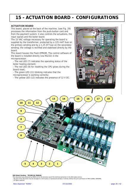
15 - ACTUATION BOARD - CONFIGURATIONS<br />
ACTUATION BOARD<br />
This board, placed at the back of the machine, (see Fig. 29)<br />
processes the information from the push-button card and<br />
from the payment system; it also controls the actuations, the<br />
input signals and the boiler board.<br />
The 15 VAC voltage necessary for operating the board is<br />
supplied by the transformer, protected by a 125 mAT fuse on<br />
the primary winding and by a 1.25 AT fuse on the secondary<br />
winding; the voltage is rectified and stabilised directly by the<br />
board.<br />
This board houses the Flash EPROM. The control software of<br />
the board is installed directly (via RS232) in the<br />
microprocessor.<br />
- The red LED (7) indicates the operating status of the<br />
boiler heating element;<br />
- The red LED (9) for resetting the CPU glows during the<br />
board reset;<br />
- The green LED (11) blinking indicates that the<br />
microprocessor is working correctly;<br />
- The yellow LED (12) indicates the presence of 12 V DC.<br />
10 11 12<br />
9<br />
8<br />
7<br />
6<br />
13<br />
5 4 3 2 1<br />
14 15 16 17 18<br />
NW Global Vending – TECHNICAL MANUAL<br />
This document was produced by MARK AC for the exclusive use of the technical personnel in the after-sales <strong>service</strong>.<br />
. No part of this document may be divulged to a third party or reproduced partially or entirely without the prior permission of NW GLOBAL VENDING<br />
. All rights reserved.<br />
New dispenser “KORO” 07/10/2005 page 20 / 42