OM, Partner, B412 X, B422 X, B462 X, B472 X, B342 B ...
OM, Partner, B412 X, B422 X, B462 X, B472 X, B342 B ...
OM, Partner, B412 X, B422 X, B462 X, B472 X, B342 B ...
You also want an ePaper? Increase the reach of your titles
YUMPU automatically turns print PDFs into web optimized ePapers that Google loves.
A EC Declaration of Conformity<br />
The undersigned, authorised by E.O.P.I., declares that the following products:<br />
Petrol Brushcutter 34-38-42-46cc, manufactured by E.O.P.I., Valmadrera,<br />
Italia, are in accordance with the European Directives 98/37/EEC (Machinery<br />
Directive), 93/68/CEE (CE Marking Directive) & 89/336/CEE (Directive on<br />
electromagnetic compatibility), directive 2000/14/CEE (Annex V).<br />
DE CE Konformitätserklärung<br />
Der Unterzeichnete, bevollmächtigt durch E.O.P.I., erklärt, daß<br />
folgende Geräte: Benzin Motorsensen 34-38-42-46cc, hergestellt<br />
durch E.O.P.I., Valmadrera, Italia, den Europäischen Richtlinien<br />
98/37/EEC (Maschinenrichtlinie), 93/68/CEE (CE<br />
Kennzeichnungsrichtlinie) & 89/336/CEE (EMV Richtlinie) entsprechen,<br />
richtlinie 2000/14/CEE (Anhang V).<br />
FR Déclaration de conformité Européenne<br />
Le soussigné, dûment mandaté par E.O.P.I., déclare que les produits<br />
suivants: Petrol Brushcutter 34-38-42-46cc, fabriqués par E.O.P.I.,<br />
Valmadrera, Italia, sont conformes aux Directives Européennes 98/37/EEC<br />
(Directive Sécurité Machine), 93/68/CEE (Directive Marquage CE) &<br />
89/336/CEE (Directive EMC), directive 2000/14/CEE (Annexe V).<br />
F EG Conformiteitsverklaring<br />
Ondergetekende, gemachtigd door E.O.P.I., verklaart dat de volgende<br />
produkten: Benzine Bosmaaier 34-38-42-46cc, geproduceerd door E.O.P.I.,<br />
Valmadrera, Italia voldoen aan de Europese Richtlijnen 98/37/CEE (Machinerie<br />
Richtlijn), 93/68/CEE (EG Markering Richtlijn) & 89/336/CEE (Richtlijn<br />
aangaande elektromagnetische compatibiliteit), richtlijn 2000/14/CEE (Annex V).<br />
NO EF Erklæring om Overensstemmelse<br />
Undertegnede, autorisert av E.O.P.I., erklærer at f¯øgende produkt<br />
Bensindrevet gress/krattrydderen 34-38-42-46cc, konstruert av E.O.P.I.<br />
23868 Valmadrera (Lecco) Via Como, 72 Italia, er i overensstemmelse med<br />
føgende europeiske direktiver: 98/37/CEE (Maskineridirektiv), 93/68/CEE (CEmerkingsdirektiv)<br />
& 89/336/CEE (Direktiv om elektromagnetisk kompatibilitet),<br />
direktiv 2000/14/CEE (Annex V).<br />
FI EY Julistus Vastaavuudesta<br />
Allekirjoittanut, E.O.P.I. in valtuttaamana, vakuuttaa että seuraavat<br />
tuotteet: Polttomoottorikäyttöinen pensasleikkuri 34-38-42-46cc,<br />
ja jotka on valmistanut E.O.P.I., Valmadrera, Italia, ovat Euroopan<br />
direktiivien 98/37/EEC (Koneisto-direktiivi), 93/68/CEE (CE Merkintädirektiivi)<br />
& 89/336/CEE (Elektromagneettinen Yhteensopivuusdirektiivi)<br />
mukainen, direktiivi 2000/14/CEE (Liite V).<br />
SE EG-försäkran om överensstämmelse<br />
Undertecknad, auktoriserad av E.O.P.I., försäkrar att följande produkter:<br />
Bensintrimmer 34-38-42-46cc, tillverkade av E.O.P.I., Valmadrera, Italia, är<br />
i överensstämmelse med följande europeiska direktiv 98/37/EEC<br />
(Maskindirektiv), 93/68/CEE (CE-märknings-direktiv) & 89/336/CEE<br />
(Elektromagnetisk kompatibilitet), direktiv 2000/14/CEE (Annex V).<br />
Electrolux Outdoor Products<br />
Via Como 72<br />
23868 Valmadrera (Lecco)<br />
ITALIA<br />
Phone +39 0341 203111 - Fax +39 0341 581671<br />
: EU Overensstemmelseerklæring<br />
ES Declaracion de cumplimiento de la directriz de la UE<br />
PT Declaração de Conformidade<br />
IT Dichiarazione di Conformità CE<br />
HU Technikai leírások<br />
@ ∆ήλωση Συµµρωσης πρς τις Eντλές της EE<br />
Our policy of continuous improvement means that the specification of products may be altered from time to time without prior notice.<br />
Electrolux Outdoor Products manufacture products for a number of well known brands under various registered patents, designs and<br />
trademarks in several countries.<br />
© Electrolux Outdoor Products Italy<br />
The Electrolux Group. The world’s No.1 choice.<br />
The Electrolux Group is the world’s largest producer of powered appliances for kitchen, cleaning and outdoor use. More than 55 million<br />
Electrolux Group products (such as refrigerators, cookers, washing machines, vacuum cleaners, chain saws and lawn mowers) are<br />
sold each year to a value of approx. USD 14 billion in more than 150 countries around the world.<br />
PN 249338 REV. 00 (11/03)<br />
Undertegnede, bemyndiget af E.O.P.I., erklærer herved, at følgende<br />
produkter: Benzindrevet Græstrimmer 34-38-42-46cc, E.O.P.I.,<br />
Valmadrera, Italia, er i overensstemmelse med de eurpæiske direktiver<br />
98/37/EEC (Maskineri direktiv), 93/68/CEE (CE mærkningsdirektiv) &<br />
89/336/CEE (EMC-direktiv), direktiv 2000/14/CEE (Annex V).<br />
El abajo firmante, autorizado por E.O.P.I., afirma que los siguientes<br />
productos: Desbrozador Gasolina 34-38-42-46cc, fabricados por E.O.P.I.,<br />
Valmadrera, Italia, cumplen con las directivas Europeas 98/37/EEC (Directiva<br />
sobre Maquinaria), 93/68/CEE (Directiva sobre Marcas de la CE) &<br />
89/336/CEE (Directiva sobre ‘Compati-bilidad Electro Magnética’), directiva<br />
2000/14/CEE (Anexo V).<br />
O abaixo assinado, autorizado por E.O.P.I., declara que os seguintes produtos:<br />
Roçadora a Gasolina 34-38-42-46cc, fabricada por E.O.P.I., Valmadrera,<br />
Italia. estão de acordo com as Directivas Europeias 98/37/EEC Directiva de<br />
Maquinaria), 93/68/CEE (Directiva de Marcação CE) e 89/336/CEE (Directiva<br />
de Compatibilidade Electromagnética), directiva 2000/14/CEE (Apêndice V).<br />
Il sottoscritto, autorizzato dalla E.O.P.I., dichiara che i seguenti prodotti:<br />
Decespugliatori 34-38-42-46cc, costruito da E.O.P.I., Valmadrera, Italia,<br />
sono conformi alle Direttive Europee: 98/37/EEC (Direttiva Macchine),<br />
93/68/CEE (Direttiva Marcatura CEE) & 89/336/CEE (Direttiva Compatibilità<br />
Elettromagnetica), direttiva 2000/14/CEE (Allegato V).<br />
Alulírott, rendelkezve a E.O.P.I. engedélyével, kijelenti, hogy a<br />
jelentermék 34-38-42-46cc, melyet a E.O.P.I. 23868 Valmadrera (Lecco)<br />
Via Como, 72 Italia, gyártott, megfelel az európai szabványoknak:<br />
98/37/CEE (gépekre vonatkozó), 93/68/CCE (márkázásnak) és<br />
89/336/CEE (elektromágneses összeegyeztetehetöségnek) megfelenek,<br />
direktíva 2000/14/CEE (Melléklet V).<br />
O υπγεγραµµένς, µε eυσιδτηση της E.O.P.I., δηλώνει τι τα<br />
εής πρϊντα: Kλαδευτήρι Bενίνης για Θάµνυς 34-38-42-46cc,<br />
κατασκευασθέντα απ την E.O.P.I., Valmadrera, Italia, HΠA<br />
ανταπκρίννται πρς τις Eυρωπαϊκές Eντλές 98/37/CEE (η περί<br />
Mηανηµάτων Eντλή), 93/68/CEE (η περί τυ Σήµατς CE Eντλή) &<br />
89/336/CEE (η περί Hλεκτρµαγνητικής Συµαττητας Eντλή),<br />
Aηρεκτηα 2000/14/CEE (Πρηπ επηε V).<br />
Valmadrera, 15.12.01<br />
Pino Todero (Direttore Tecnico)<br />
E.O.P.I.<br />
GB<br />
DE Handha-bung des Geräts aufmerksam durch. Verwenden ES<br />
FR<br />
NL<br />
NO<br />
FI<br />
SE<br />
INSTRUCTION MANUAL<br />
IMPORTANT INFORMATION: Please read these instructions<br />
carefully and make sure you understand them before using<br />
this unit. Retain these instructions for future reference.<br />
BETRIEBSANWEISUNG<br />
WICHTIGE INFORMATION: Lesen Sie diese Hinweise zur<br />
Sie es erst, wenn Sie sicher sind, daß Sie alle<br />
Anweisungen verstanden haben und gut aufbewahren.<br />
MANUEL D’INSTRUCTIONS<br />
RENSEIGNEMENTS IMPORTANTS: Avant d’utiliser cet<br />
appareil, veuillez lire atentivement les instructions et<br />
assurez-vous de les avoir comprises. Conservez les<br />
instructions pour référence ultérieure.<br />
HANDLEIDING<br />
BELANGRIJKE IMPORTANTS: Lees deze handleiding<br />
aandachtig en zorg dat u ailes begrijpt alvorens de kettingzaag<br />
te gebrulken en be-waar ze voor toekomstige raadpleging.<br />
BRUKERHÅNDBOK<br />
VIKTIG INFORMASJON: Les disse anvisningene nøye<br />
og forsikre deg om at du forstår dem før du bruker<br />
enheten og oppbevar dem for sen-ere bruk.<br />
OHJEKIRJA<br />
TÄRKEÄÄ TIETOA: Lue nämä ohjeet huolellisesti ja<br />
varmista, että olet ymmärtänyt ne, ennen kuin alat<br />
käyttää tätä laitetta ja säilytä myöhempää tarvetta<br />
varten.<br />
BRUKSANVISNING<br />
VIKTIG INFORMATION: Läs instruktionerna noggrant och<br />
försäkra dig om att du förstår dem innan du använder<br />
utrustningen och spara dem för framtida behov.<br />
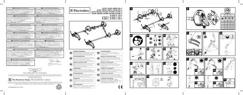
ELITE 3325-3425/34 cc<br />
ELITE 3825-3925-3930/38 cc<br />
ELITE 4230x-4330x-4330XPRO/42 cc<br />
ELITE 4630x-4730x-4730XPRO/46 cc<br />
B 342 X / 34 CC<br />
B 412 X - B 422 X / 42 CC<br />
B 462 X - B 472 X / 46 CC<br />
DK<br />
PT<br />
IT<br />
HU<br />
GR<br />
BRUGERHÅNDBOG<br />
VIGTIGE OPLYSNINGER: Læs instruktionerne<br />
omhyggeligt, før du bruger enheden og gemme til<br />
senere henvisning.<br />
MANUAL DE INSTRUCCIONES<br />
INFORMACIÓN IMPORTANTE: Lea atentamente las<br />
instrucciones y asegúrese de entenderlas antes de<br />
utilizar esta aparato. Conserve las instrucciones para la<br />
referencia en el futuro.<br />
MANUAL DO OPERADOR<br />
INFORMAÇÕES IMPORTANTES: Queira ler<br />
cuidadosamente estas instruções e tenha certeza de<br />
entendë--las antes de usar a serra e guarde para<br />
consulta futura.<br />
LIBRETTO D’ISTRUZIONI<br />
INFORMAZIONI IMPORTANTI: Leggere le istruzioni<br />
attentamente e capirle bene prima di usare l’utensile.<br />
Conservare per ulteriore consultazione.<br />
HASZNÁLATI ÚTMUTATÓ<br />
Jótállást vállalni csak rendeltetésszerüen használatba<br />
vett gépekre tudunk. Kérj ü hogy a gép használatba<br />
vétele elött gondosan olvassa el a kezelési utasításokat.<br />
EΓXEIPI∆IO XEIPIΣMOE<br />
ΣHMANTIKEΣ ΠΛHPOΦOPIEΣ: ∆ιαάστε<br />
πρoσεxτιxά αvτές τις δηγίες xαι Φρovτίστε vα τις<br />
xαταvoήσετε αvτ τo µηάvηµα xαι Φuλάτε τ για<br />
vα τ σuµuλεύεστε στ µέλλv.<br />
A<br />
B1 B2 B3<br />
B4 B5 B6<br />
C1 C2 C3<br />
C4 C5<br />
D<br />
E1 E2<br />
E3<br />
F1 F2 F4<br />
F3 F3<br />
F3 F3<br />
<strong>Partner</strong><br />
oil<br />
50:1<br />
1 ltr 20 cm 3 25 cm 3 40 cm 3<br />
4 80 100 160<br />
5 100 125 200<br />
10 200 250 400<br />
20 400 500 800<br />
F5<br />
McCulloch<br />
oil<br />
2T<br />
oil<br />
40:1 25:1<br />
2% 2,5% 4%
G1<br />
G3<br />
I1<br />
G2<br />
G4<br />
H1 H2<br />
H3<br />
I2 I3<br />
I4 I5<br />
L<br />
A<br />
B<br />
M1<br />
M2<br />
M3 M4<br />
N1<br />
N2 N3<br />
N4 N5 N6<br />
N7 N8 N9<br />
O<br />
0,095”<br />
2.4mm<br />
3.0mm<br />
4T<br />
4T<br />
8T<br />
8T<br />
24T<br />
80T<br />
197”<br />
5000mm<br />
9”<br />
230 mm<br />
10”<br />
255 mm<br />
9”<br />
9”<br />
230mm<br />
10”<br />
255mm<br />
230mm<br />
9”<br />
230mm<br />
42/46 cc 34/38 cc<br />
538242506<br />
248960<br />
226134B<br />
248960<br />
226135B<br />
248960<br />
236711B<br />
248960<br />
236713B<br />
248960<br />
240998B<br />
240936B<br />
240553<br />
236677<br />
240953B<br />
240936B<br />
240553<br />
236677<br />
240853B<br />
248959<br />
226134B<br />
248959<br />
226135B<br />
248959<br />
236711B<br />
248959<br />
236713B<br />
248959<br />
240998B<br />
240936B<br />
240553<br />
236677<br />
240953B<br />
240936B<br />
240553<br />
236677<br />
GB SUMMARY CHART TO IDENTIFY THE<br />
CORRECT GUARD NEEDED, WITH<br />
DIFFERENT CUTTING ATTACHMENTS<br />
DE ÜBERSICHTSTABELLE ZUR AUSWAHL DES<br />
RICHTIGEN SCHUTZBLECHES FÜR DIE<br />
EINZELNEN SCHNEIDWERKZEUGE<br />
FR TABLEAU RECAPITULATIF POUR LE<br />
CORRECT ACCOUPLEMENT LAME OU<br />
TETE FIL NYLON / DEFENSE DE SECURITE<br />
NL OVERZICHTSTABEL <strong>OM</strong> TE BEPALEN WELKE<br />
BESCHERMKAP GEBRUIKT MOET WORDEN<br />
BIJ DE DIVERSE MAAI-ONDERDELEN<br />
NO TABELL FOR KORREKT MONTERING AV<br />
TRÅDSPOLE/SAGBLAD OG<br />
SPRUTSKJÆRM/SIKKERHETSVÆRN<br />
FI TAULOKKO LEIKKAAVAN<br />
PÄÄN/TURVASUOJUKSEN OIKEASTA<br />
YHDISTELMÄSTÄ<br />
SE SAMMANFATTANDE TABELL ÖVER<br />
KORREKT K<strong>OM</strong>BINATION AV<br />
SKÄRHUVUD/SÄKERHETSSKYDD<br />
DK OVERSIGTSTABEL VEDRØRENDE DEN<br />
KORREKTE SAMMENSÆTNING AF KNIV<br />
OG BESKYTTELSESSKÆRM<br />
ES TABLA PARA EL CORRECTO<br />
ACOPLAMIENTO DE LA CABEZA<br />
CORTANTE Y PROTECTOR DE SEGURIDAD<br />
PT TABELA DE RESUMO PARA A CORRETA<br />
APLICAÇÃO DA CABEÇA CORTANTE E<br />
DEFESA DE SEGURANÇA<br />
IT TABELLA RIASSUNTIVA PER IL CORRETTO<br />
ABBINAMENTO TESTA TAGLIENTE / DIFESA<br />
DI SICUREZZA<br />
HU ÖSSZEFOGLALÓ TÁBLÁZAT: A NYÍRÓFEJ<br />
ÖSSZEÁLLITÁSA / BALESETVÉDELEM<br />
GR ΠEPIΛHΠTIKOΣ ΠINAKAΣ ΓIA THN<br />
EΠIΣHMANΣH TOY KATAΛΛHΛOY<br />
ΠPOΦYΛAKTHPA, ME ∆IAΦOPA KOΠTIKA<br />
EAPTHMATA<br />
GB Due to a constant product improvement programme, the factory<br />
reserves the right to modify technical details mentioned in this<br />
manual without prior notice.<br />
DE Im Sinne des Fortschritts behält sich der Hersteller das Recht<br />
vor, technische Änderungen ohne vorherigen Hinweis<br />
durchzuführen.<br />
FR La Maison se réserve la possibilité de changer des<br />
caractéristiques et des données de ce manuel à n’importe quel<br />
moment et sans préavis.<br />
NL Door konstante produkt ontwikkeling behoud de fabrikant zich<br />
het recht voor om rechnische specificaties zoals vermeld in deze<br />
handleiding te veranderen zonder biervan vooraf bericht te<br />
geven.<br />
NO Produsenten forbeholder seg all rett og mulighet til å forandre<br />
tekniske detaljer i denne manualen uten forhåndsvarsel.<br />
FI Jatkuvan tuotteen parannusohjelman tähden valmistaja pidättää<br />
oikeuden vaihtaa ilman ennakkovaroitusta tässä ohjekirjasessa<br />
mainittuja teknisiä yksityiskohtia.<br />
SE Tilverkaren reserverar sig rätten att ändra fakta och uppgifter ur<br />
handboken utan förvarning.<br />
DK Producenten forbeholder sig ret til ændringer, hvad angår<br />
karakteristika og data i nærværende instruktion, når som helst<br />
og uden varsel.<br />
ES La firma productora se reserva la posibilidad de cambiar las<br />
características y datos del presente manual en cualquier<br />
momento y sin previo aviso.<br />
PT A casa productora se reserva a possibilidade de variar<br />
características e dados do presente manual em qualquer<br />
momento e sen aviso prévio.<br />
IT La casa produttrice si riserva la possibilità di variare<br />
caratteristiche e dati del presente manuale in qualunque<br />
momento e senza preavviso.<br />
HU A gyártó cég fenntartja a jogot arra, hogy a használati<br />
utasitásban megadott adatokon és technikai tulajdonságokon<br />
bármikor és elözetes bejelentés nélkül változtasson.<br />
GR Λγω πργράµµατς συνεύς ελτίωσης πρϊντων, τ<br />
εργστάσι επιυλάσσεται τυ δικαιώµατς να<br />
τρππιεί τις τενικές λεπτµέρειες πυ αναέρνται<br />
στ εγειρίδι αυτ ωρίς πρηγύµενη ειδπίηση.
1) ENGINE<br />
2) SHAFT<br />
3) THROTTLE TRIGGER<br />
4) DEC<strong>OM</strong>PRESSION VALVE<br />
5) RIGHT CONTROL HANDLE<br />
6) BLADE<br />
7) NYLON STRING HEAD<br />
8) STOP SWITCH<br />
9) CHOKE LEVER<br />
10) STARTER HANDLE<br />
11) HARNESS RING<br />
Explanation of Symbols<br />
If not used properly this Petrol Brushcutter can be dangerous.<br />
The warnings and safety instructions must be followed to ensure reasonable<br />
safety and efficiency in using this product.The operator is responsible<br />
for following the warnings and instructions in this manual and on the<br />
product.<br />
Warning<br />
Wear safety clothing:<br />
Approved safety glasses or face<br />
shield<br />
Wear safety clothing:<br />
Approved ear defender<br />
Wear safety clothing:<br />
Approved safety footwear<br />
Do not use metal blades<br />
A. General description<br />
Safety precautions<br />
12) SPARK PLUG<br />
13) AIR FILTER<br />
14) FUEL TANK CAP<br />
15) MUFFLER SHIELD<br />
16) ENGINE SHAFT JOINT<br />
17) FRONT HANDLE<br />
18) REAR CONTROL GRIP<br />
19) SAFETY GUARD<br />
20) SAFETY GRIP<br />
21) SAFETY POLE BARRIER<br />
MAX. 0000 Min -1<br />
Read the user instructions carefully<br />
o make sure you understand all<br />
the controls and what hey do.<br />
Wear safety clothing:<br />
Approved safety helmet<br />
Wear safety clothing:<br />
Approved gloves<br />
Do not smoke while refuelling<br />
or while operating<br />
the trimmer<br />
Maximum blade speed<br />
ENGLISH - 1
ENGLISH - 2<br />
Blade thrust Beware of projected objects<br />
Maximum safety distance<br />
Choke closed (cold start)<br />
1) Make sure all operators study this manual carefully<br />
before using the trimmer; only use this machine for<br />
usage specifically mentioned in this manual.<br />
Never allow children to use the trimmer.<br />
2) When working with the trimmer wear suitable<br />
clothes: a) Close fitting protective clothes ( do not<br />
wear short trousers or loose clothes). b) Safety shoes<br />
(do not wear sandals and do not work barefoot). c)<br />
Heavy-duty gloves. d) Safety face shield or goggles.<br />
Ensure you peel off the protective films, if existing,<br />
from the see - through plastic. e) Ear protection. f)<br />
Head protection when using circular saw blades.<br />
Make sure you know how to stop the engine in an<br />
emergency (see the section STARTING AND STOP-<br />
PING ENGINE). Never use the trimmer when tired,<br />
physically indisposed or under the effect of alcohol,<br />
certain medicines or other drugs. Be careful of the<br />
rotating cutting attachment and hot surfaces on the<br />
unit.<br />
3) Prolonged use of this product or other machines<br />
exposing the operator to vibration may produce<br />
Whitefinger’s disease (Raynaud’s Phenomenon). This<br />
may reduce the hands’ ability to feel and regulate<br />
temperature and may produce general numbness.<br />
Continual or regular users should therefore monitor<br />
closely the condition of their hands or fingers. If any<br />
of the symptoms appear, seek immediate medical<br />
advice. Always hold the trimmer firmly with both<br />
hands. When working maintain a firm foothold. The<br />
trimmer must be used exclusively as recommended<br />
(see section SAFETY USAGE).<br />
4) Do not carry the trimmer while the engine is running<br />
even for short distances; switch off the engine and<br />
carry the unit with the cutting head behind you.<br />
When carrying the trimmer in a vehicle, secure it to<br />
avoid fuel leakage. Always empty the fuel tank before<br />
transporting the unit. ATTENTION: For your<br />
safety the blade must be kept at all times in its prop-<br />
B. Safety precautions<br />
Choke fully opened<br />
(hot start / run)<br />
er case during transport and storage. Start the trimmer<br />
on a flat surface. When starting the unit, ensure<br />
you have a firm footing. Make sure the blade or the<br />
nylon string head does not touch the ground or any<br />
obstacle.<br />
5) PRECAUTIONS AGAINST FIRE: do not operate the<br />
trimmer near fire or spilled petrol. Do not run the<br />
engine in closed or poorly ventilated areas.<br />
EXHAUST GASES ARE POISONOUS WHEN<br />
INHALED, THEY CAN CAUSE SUFFOCATION AND<br />
DEATH.<br />
After refuelling always wipe off any spilled fuel. Do not<br />
smoke during this operation. Start the engine far<br />
away from the refuelling area and from fuel containers<br />
(minimum distance 3 meters). Do not refuel while the<br />
engine is still running.<br />
6) Keep people and animals away from working area<br />
(minimum distance 15 meters). If somebody should<br />
approach you, turn the engine off and stop the blade<br />
or the rotating head (see chapter STARTING AND<br />
STOPPING THE ENGINE) as during operation the<br />
blade or the nylon string head might project grass,<br />
grit, or other debris. The blade is sharp, be careful<br />
even if handling it when the engine is off.<br />
Wear heavy-duty gloves. Turn the engine off and wait<br />
for rotating parts to stop completely before working<br />
on the machine or before touching the blade or the<br />
string head above all to remove possible entangled<br />
material.<br />
DO NOT USE THE MACHINE AT ALL IF THE SPEC-<br />
IFIED SAFETY GUARD IS NOT FIRMLY ATTACHED<br />
(see sections SAFETY USAGE and BLADES AND<br />
NYLON STRING HEAD ASSEMBLY).<br />
Pay careful attention to safety recommendations as<br />
you might put your life or somebody else’s in danger<br />
as a result of: a) possible contact with cutting or<br />
rotating parts. b) possibility of projection of various<br />
objects.
WARNING: do not start engine if it is not attached to<br />
the shaft as the clutch might disintegrate. For units<br />
This product must be held to the right of the operator’s<br />
body.<br />
This will ensure exhaust fumes are directed away from<br />
the operator and will not be obstructed by the operator’s<br />
clothing. If you have not used a trimmer before,<br />
spend some time in becoming familiar with the controls<br />
and method of usage before operation.<br />
Check the machine carefully before using it.<br />
Make sure that there are no loosened screws, damaged<br />
parts or fuel leakages.<br />
Replace damaged or excessively worn accessories<br />
(blades, string heads, guards).<br />
Ensure all maintenance or repair work is carried out by<br />
an authorised service center.<br />
N.B. In order to maintain performance and safety, be<br />
sure to use original spare parts and accessories.<br />
Avoid using the trimmer over excessively long periods<br />
of time.<br />
Excessive amounts of vibration can be harmful.<br />
1) Remove from the working area grit, debris, ropes,<br />
metal parts or any other object which might get<br />
entangled around the rotating parts or be dangerously<br />
projected.<br />
Use only the correct accessory recommended for<br />
the type of vegetation to be cut. Do not let the rotating<br />
blade contact any foreign object such as stones,<br />
rocks, cans etc.<br />
Secure hair to keep it above shoulder height. Before<br />
starting to work fit the harness. Adjust harness with<br />
the buckle so that the trimmer is well balanced on<br />
your right side and the blade or string head is parallel<br />
to the ground. Always maintain a firm foothold and a<br />
good balance while using the machine. Do not move<br />
backwards while you work as obstacles may not be<br />
visible.<br />
The fitting of the safety pole barrier is obligatory on<br />
units equipped with a delta shaped handle when<br />
used with a metal blade.<br />
The purpose of this safety pole barrier is to maintain<br />
a safe distance between the metal blade and the<br />
user under all normal or exceptional circumstances.<br />
2) Harness ring (B) must never be moved from its original<br />
position to avoid unbalancing the unit.<br />
Front handles can be separately adjusted to make<br />
usage easier on units fitted with “U” shaped handles.<br />
3) The following accessories can be assembled to your<br />
trimmer: a) blade, b) nylon string head.<br />
Do not attach any blade to a unit without proper<br />
installation of all required parts. Failure to use the<br />
proper parts can cause the blade to fly off and seriously<br />
injure the operator and/or bystanders.<br />
a) WHEN USING A BLADE ENSURE THE COR-<br />
C . Safety usage<br />
equipped with a clutch, be sure the cutting attachment<br />
stops turning when the engine idles.<br />
RECT GUARD IS FITTED.<br />
b) WHEN USING A NYLON STRING HEAD ENSURE<br />
THE CORRECT GUARD IS FITTED.<br />
When using the unit always hold the front part of the<br />
machine (blade or nylon string head) below your<br />
waist.<br />
NYLON STRING HEAD:<br />
Always make sure it has been correctly assembled<br />
and fitted.<br />
The nylon head is suitable to cut grass and weeds<br />
wherever there might be obstacles like trees, fences<br />
or walls.<br />
The nylon string head also reduces the likelihood of<br />
damaging small plants and trees bark.<br />
Only use flexible, nonfilament nylon line in the nylon<br />
line head as specified by the manufacturer. Never<br />
use metallic line which could break off and become a<br />
dangerous projectile.<br />
BLADE:<br />
Always make sure it has been correctly fitted.<br />
When fitting or changing a cutting device, ensure you<br />
follow the instructions in the section “Blade or nylon<br />
string head assembly” with extreme precision. Fit<br />
these cutting devices using all and only the parts as<br />
described, and in the correct order.<br />
4) BLADES: you can cut any type of grass, brushwood<br />
or shrub.<br />
Operate the machine like a sickle always cutting at<br />
full throttle.<br />
5) WARNING: always use a well sharpened blade.<br />
A blade with worn teeth besides providing poor performance<br />
might also generate a sudden thrust. This<br />
can result in a violent sideways kick caused when<br />
the blade touches against wood or solid bodies,<br />
such thrust might then cause the operator to loose<br />
control of the machine itself. Never attempt to work<br />
with a damaged blade but replace it with a new one.<br />
THRUST: can occur when using any type of circular<br />
blade within the risk area: therefore it is advisable to<br />
cut using the remaining area of the blade.<br />
CIRCULAR SAW BLADE: it can be used to cut sappling,<br />
small trees with a diameter up to 7 cm., to<br />
clean shrubs.<br />
WARNING: IF A METAL 24-80 TOOTH BLADE (A<br />
SAW TOOTH BLADE) IS USED A DOUBLE<br />
SHOULDER HARNESS AND A SAFETY GUARD<br />
(PROTECTION) MUST ALSO BE USED AS MARKED<br />
IN THE SUMMARY CHART (SEE CLOTHES SECTION<br />
IN SAFETY CHAPTER: ALWAYS WEAR A HELMET).<br />
ALWAYS USE GENUINE ACCESSORIES AND<br />
SPARE PARTS AVAILABLE FR<strong>OM</strong> AUTHO-<br />
RISED SERVICING DEALERS. THE USE OF<br />
ENGLISH - 3
NON-ORIGINAL ACCESSORIES AND SPARE<br />
PARTS INCREASES THE RISK OF ACCIDENTS<br />
AND IN SUCH A CASE THE C<strong>OM</strong>PANY IS NOT<br />
Do not use any other type of fuel than the type<br />
recommended in this manual.<br />
This product is equipped with a two-stroke<br />
engine and must therefore use a mixture of<br />
lead-free gasoline (with a minimum of 90<br />
octanes) and fully synthetic oil for two-stroke<br />
engines, specific for lead-free gasoline in the<br />
proportions indicated in the table on the cover<br />
page at item (D).<br />
IMPORTANT! Read the oil specifications on<br />
the can carefully: the use of oil lacking the<br />
specifications indicated in this manual can<br />
cause severe damage to the engine!<br />
To obtain the best mixture, pour the oil first, followed<br />
by the gasoline, into an approved container,<br />
shake well (repeat the operation every time<br />
you draw any fuel from the container).<br />
The characteristics of the mixture are subject to<br />
aging and may be altered in time, so we recommend<br />
mixing only the amount strictly needed for<br />
use. If you use a mixture that is several weeks<br />
old, this could damage the engine.<br />
1) In the interest of safety, it is imperative that the<br />
unit is used with the correct guard (P/N 248959<br />
Ø25 P/N 248960 Ø30) when using any blade or a<br />
nylon string head, except the 24-80 tooth blade.<br />
Line cutter blade (L): assemble as illustrated E1.<br />
2-3) When using a saw tooth blade (optional<br />
accessory), the correct guard must be fitted (P/N<br />
240553).<br />
A double shoulder harness must also be worn.<br />
ENGLISH - 4<br />
D. Fuel mix<br />
E. Safety guard assembly<br />
LIABLE FOR DAMAGE TO PEOPLE AND/OR<br />
THINGS.<br />
Only use blades or nylon string heads clearly<br />
marked with a maximum speed of at least 10,500<br />
min -1 .<br />
Follow the fitting instructions carefully.<br />
N.B: Saw tooth blades (24 - 80 tooth) have a<br />
central base diametre of 20mm and therefore<br />
require the use of the appropriate size top flange<br />
to ensure a correct fit. The part number is<br />
detailed in the cutting attachment summary chart.<br />
F. Blade and nylon string head assembly<br />
Assemble the correct guard to suit the kind of<br />
blade or nylon string head to be used (See section:<br />
SAFETY GUARD ASSEMBLY).<br />
1) Assemble blade as illustrated:<br />
a) Flange guard - b) Upper cap with blade<br />
centering - c) Blade with text and directional<br />
arrow facing upwards - d) Lower washer - e)<br />
Fixed mower gauge - f) Blade locking screw<br />
(length mm 16).<br />
2) If you want to assemble the rotating mower<br />
gauge,proceed as illustrated:<br />
a) Flange guard - b) Upper cap with blade<br />
centering - c) Blade with text and directional<br />
WARNING<br />
Do not smoke when re-fuelling.<br />
Always open the fuel cap slowly, to release any<br />
pressure build up in the tank.<br />
Re-fuel in open spaces only, keeping away from<br />
naked flames or sparks.<br />
SAFE STORAGE OF FUEL<br />
Petrol fuel mix is highly inflammable.<br />
Put out all cigarettes, pipes and cigars before<br />
working with fuel.<br />
Avoid spilling fuel. Store fuel in a cool, well ventilated<br />
place, in an approved container specifically<br />
designed for the purpose.<br />
Never store engine with fuel in the tank in<br />
enclosed, poorly ventilated areas where fuel<br />
fumes may reach an open flame, spark or pilot<br />
light such as in a furnace, water heater, clothes<br />
dryer etc. Petrol fumes can cause an explosion or<br />
a fire. Never store large amounts of fuel.<br />
To prevent possible restarting problems avoid<br />
running the fuel tank dry.<br />
This also helps to extend engine life.<br />
arrow facing upwards - d) Lower washer - e)<br />
Spacer - f) Rotating mower gauge - g) Blade<br />
locking screw (length mm 34,5).<br />
Replace the blade attachment bolt if damaged<br />
in any way.<br />
3) Make sure that the blade bore opening fits perfectly<br />
around the centering collar on the upper cap.<br />
Tighten counterclockwise.<br />
While tightening, the blade assembly can be<br />
held fast by inserting the wrench or the screwdriver<br />
supplied into the cap and gearcase<br />
holes.
To do this, rotate the cap intil the two holes<br />
coincide.<br />
4) Assemble nylon string head as illustrated:<br />
a) Flange guard - b) Upper cap - c) Guard d)<br />
Nylon string head<br />
Tighten counterclockwise.<br />
BACK-PACK BRUSHCUTTER<br />
See sections BACK-PACK BRUSHCUTTER.<br />
DANGER. Do not run engine without shaft<br />
attached as clutch could fly off.<br />
1) Assemble the engine onto the shaft. Make sure<br />
the shaft is fully and correctly engaged up to<br />
the shank, then tighten the 2 screws (A) in a<br />
criss-cross sequence.<br />
1) DOUBLE HANDLE<br />
Handle (A) can be adjusted for individual<br />
operator comfort by swivelling it forwards or<br />
backwards. To do this, loosen button (C),<br />
position the handle for maximum comfort,<br />
then tighten button (C) securely. Clip the<br />
suspension harness hook into one of the 5<br />
holes on the top side of the shaft support to<br />
achieve the best balance according to the<br />
type of work to be undertaken.<br />
NB: Handle assembly (A) can be folded<br />
parallel to the shaft to facilitate<br />
transportation or storage. To do this,<br />
loosen knob (C), twist support (B) 90° in a<br />
clockwise direction, fold the handle (A)<br />
into the required position and then tighten<br />
knob (C).<br />
WARNING: Before using the product every user<br />
should carefully read the sections SAFETY,<br />
SAFETY USAGE and SYMBOL MEANINGS.<br />
STARTING A COLD ENGINE<br />
1) Position the on/off switch to the I (ON)<br />
position, away from the «STOP» position.<br />
2) Rotate the choke lever in the direction illustrated<br />
by the arrows. This engages the fast idle system.<br />
3) Squeeze the primer bulb (C) several times<br />
until you see fuel begin to return back<br />
through the tube (D) towards the fuel<br />
tank. Push the decompression valve (B)<br />
G. Engine/shaft assembly<br />
H. Handle assembly<br />
5) While tightening, the head assembly can be<br />
held fast by inserting the wrench or the screwdriver<br />
supplied into the holes as already shown<br />
for blade assembly.<br />
WARNING: Do not use the guard for the nylon<br />
string head when using a metal blade.<br />
2) Fit the end of the trigger cable connector (B)<br />
into the slot on swivel (C).<br />
3) Adjust the screw (D) of the trigger cable<br />
connector so that the cable can easily slide in<br />
the opening with a play of 1 mm before operating<br />
the swivel (C).<br />
Tighten now the hexagonal nut (E).<br />
4A) Stop switch (STOP) cable: fit the connection.<br />
4B) Earth lead: connect as illustrated.<br />
2) DELTA FRONT HANDLE<br />
Secure the handle in front of the label<br />
placed on the shaft 11 cm from the rear<br />
grip when assembling nylon string head<br />
and 36 cm when assembling metallic<br />
blades. This position ensures optimum<br />
balance and safety. The handle must be<br />
perpendicular to the shaft as illustrated<br />
(Fig.2).The handle bar must be mounted<br />
using all the items supplied and in the<br />
exact configuration shown in figures 1 or 2.<br />
3) DOUBLE HANDLE<br />
Adjust and secure double hand clamp by tightening<br />
the screws.<br />
I. Starting and stopping the engine<br />
down if your models is fitted with one. Pull<br />
the starter handle until the engine starts.<br />
4) Hold the machine safely and allow the<br />
engine to run for a few seconds. Grip the<br />
control handle firmly, pushing down on the<br />
safety trigger (S) and then squeezing the<br />
accelerator trigger (A). This action automatically<br />
releases the spring loaded choke lever (E) disengaging<br />
the fast idle system.<br />
WARNING: The fast idle system does<br />
cause the cutting attachment to rotate<br />
when engaged.<br />
ENGLISH - 5
STARTING A WARM ENGINE<br />
Position the on/off switch to the I (ON) position.<br />
Squeeze the primer bulb (C) several times until<br />
you see fuel begin to return back through tube<br />
(D) to the fuel tank. Push the decompression<br />
valve (B) down if your model is fitted with one.<br />
Pull the starter handle until the engine runs.<br />
5) STOPPING THE ENGINE<br />
Push the on/off switch to the STOP position.<br />
WARNING: After the engine has been<br />
To adjust the idle speed, however, proceed as follows:<br />
With engine running and warm, slowly turn screw<br />
‘T’ clockwise until the engine runs smoothly with<br />
a consistent noise level but without making the<br />
cutting head rotate.<br />
From time to time ensure all screws are tight.<br />
Replace damaged, worn, cracked or warped<br />
blades. Always make sure nylon string head or<br />
blade have been assembled correctly (see sections<br />
NYLON STRING HEAD and BLADE<br />
ASSEMBLY) and blade fastener is tightened.<br />
1) AIR FILTER CLEANING<br />
(at least every 25 working hours).<br />
A dust clogged air filter may cause carburetor<br />
problems.<br />
This may prevent the engine from reaching its<br />
maximum speed and cause high fuel consumption<br />
and/or difficult starting.<br />
Remove filter cover as shown in figure 1.<br />
Carefully clean the inside of filter box. The filter<br />
can also be cleaned with compressed air.<br />
N.B. Slide the air filter back into its location (C)<br />
ensuring the tabs (A) are pointing downwards as<br />
illustrated, ensure it clicks firmly into its airtight<br />
position.<br />
2) Every 50 working hours inject the gearcase with<br />
gear grease under high pressure through hole<br />
(C).<br />
ENGLISH - 6<br />
L. Carburettor adjustment<br />
M. Regular maintenance<br />
switched off, the rotating cutting attachment,<br />
blade or string head, will continue to rotate for<br />
a few seconds due to their inertia. Continue to<br />
hold the machine firmly off the ground until it<br />
stops completely. Keep your hands away whilst<br />
it is moving.<br />
N.B. In an emergency, the cutting<br />
attachment can be stopped quickly by<br />
touching it parallel to the ground after<br />
moving the switch to the «STOP» position.<br />
If the cutting attachment does move or the engine<br />
runs too fast, slowly turn screw ‘T’ in an anticlockwise<br />
direction until the correct speed is<br />
obtained.<br />
Precise numerical engine speed settings are mentioned<br />
in the technical detail chart in the front of<br />
the owner’s manual.<br />
3) SPARK PLUG<br />
From time to time (at least every 50 hours)<br />
remove and clean the spark plug and check<br />
the electrode gap (0,5/0,6 mm.). Replace spark<br />
plug about every 100 working hours or whenever<br />
it is extremely encrusted. Heavily encrusted<br />
electrodes can result from wrong fuel mixture<br />
(too much oil in the petrol) or a poor quality of<br />
oil in the fuel mix. Check and correct.<br />
4) FUEL FILTER<br />
To change fuel filter remove the tank cap and<br />
pull out the filter with a piece of bent wire or<br />
long forceps. Contact your Service Station for<br />
general servicing and cleaning of internal parts<br />
at least once a year.This will reduce the possibility<br />
of unexpected problems and will ensure<br />
maximum product life and efficiency.<br />
REGULARLY: it is important, in order to avoid<br />
engine overheating, to remove dust and dirt<br />
from slots, gaps and from in between cylinder<br />
fins using a wooden scraper.<br />
LONG STORAGE: empty fuel tank and run<br />
engine until dry.<br />
Store trimmer in a dry place.
1) Loosen the locking nut on the base of the<br />
nylon head by turning it clockwise.<br />
2) Remove the base cover assembly.<br />
Remove the empty spool from the housing and<br />
discard any remaining line.<br />
REWINDING NEW LINE<br />
3) Prepare 2 lengths (8ft each) of 2.4 mm nylon<br />
line. Thread 1 end of each line into the two<br />
holes on opposite sides of the spool. Pinch the<br />
exposed ends flat with a pair of pliers to prevent<br />
them slipping through the hole.<br />
4) Wind the two lines in the same direction<br />
around the spool.<br />
This chapter is about how to maintain the ” eco features”<br />
of the machine as originally developed by our<br />
engineers, the correct use of this machine and handling<br />
of waste oil and fuel.<br />
1. Research on the 4 stroke engine has been developed<br />
in order to produce lower fuel consumption<br />
and low emission of polluting exhaust gases<br />
2. Use of the machinery: During the fuel filling operation<br />
particular care should be taken to avoid<br />
N. Replacing nylon line<br />
O. Ecology<br />
Technical data<br />
REASSEMBLY<br />
5) Slide the end of the two lines into the grooves<br />
to hold the line temporarily.<br />
6) Position the spool back into the housing and<br />
pull the line through the eyelets.<br />
7) Pull about 12cm (5ins) of line out on either<br />
side.<br />
8) Reassemble the nylon string head as illustrated;<br />
mower gauge,spring and locking nut (tighten<br />
in an anti-clockwise direction).<br />
9) N.B: In order to extend the nylon line as it<br />
wears down, pull the mower gauge downwards<br />
and turn it in a clockwise direction to<br />
feed out the desired length of line.<br />
waste fuel polluting the enviroment.<br />
3. When storing for a long period, empty fuel tank<br />
and run engine until dry, observing the same precautions<br />
as when filling.<br />
4. Disposal of machines: Old machines can be very<br />
dangerous for the environment - do not throw<br />
them awway!! Please apply to the compotent<br />
body authorised to collect industrial waste. As<br />
prescribed by National laws on enviroment<br />
DISPLACEMENT (cm3) 34 38 42 46<br />
BORE AND STROKE (mm) 38x30 40x30 41x32 43x32<br />
ENGINE OUTPUT (Kw) 1,2 1,3 1,6 1,8<br />
ENGINE SPEED AT MAX POWER (min-1) 8.000 8.000 8.000 8.200<br />
MAXIMUM SPEED, NO LOAD (min-1) 10.000 10.000 10.000 11.000<br />
MINIMUM SPEED (min-1) 2.800 2.800 2.800 2.800<br />
BLADE SHAFT SPEED (min-1) 7.700 7.700 7.700 8.500<br />
BLADE LOCKING NUT TIGHTENING TORQUE (Nm) 17 17 17 17<br />
DRY WEIGHT (kg) 7,1 7,3-8,3 PRO 7,4-8,4 PRO-8,8 BP 7,7-8,7 PRO-10,8 BP<br />
FUEL TANK CAPACITY (cm3) 900 900 900 900<br />
SOUND PRESSURE LEVEL (AT THE OPERATOR’S EAR) LpAav (dBA) (ISO7917) 97 97 97 106<br />
GUARANTEED NOISE LEVEL LwAav (dBA) (ISO 10884) 114 114 114 114<br />
MEASURED SOUND POWER LEVEL LwAav (dBA) (ISO 10884) 113 113 113 113<br />
VIBRATIONS LEVEL STRING HEAD (ISO 7916) (m/s2) MAX-MIN 8,2-1,6 8,2-1,7 10,55-1,8 12,5-1,06<br />
VIBRATIONS LEVEL BLADE (ISO 7916) (m/s2) MAX-MIN 8,2-1,6 8,2-1,7 16,38-1,8 17,79-1,06<br />
ENGLISH - 7
Check STOP switch is in the position<br />
I.<br />
Control fuel level min. 25%tank<br />
capacity.<br />
Check air filter is clean.<br />
Remove spark plug, dry it, clean it<br />
and adjust it, and replace it, if necessary.<br />
Change fuel filter. Contact your dealer.<br />
Carefully follow the cutting accessory<br />
assembly instructions.<br />
Check metal cutting accessory is<br />
sharp. Otherwise, contact your dealer.<br />
Fault finding table<br />
Engine still gives trouble: contact your dealer.<br />
ENGLISH - 8<br />
Engine will<br />
Engine runs badly The machine<br />
not start<br />
or looses power runs but does<br />
when cutting not cut well<br />
•<br />
• •<br />
• •<br />
• •<br />
•<br />
•<br />
•
A BACK-PACK BRUSHCUTTER<br />
1 Insert the flexible drive shaft onto the engine connector (G). Ensure the<br />
male square end of the shaft engaged firmly into the female square end of<br />
the connector. Insert throttle cable and electrical wires (A) into the<br />
retaining guide (B) far enough to allow the necessary connections to<br />
be made (see Fig. 1A).<br />
Tighten screw (V) ensuring it locates correctly into its opening (S). Now the<br />
shaft is firmly fixed in the connector.<br />
DE MOTORSENSE - RÜCKENGERÃT<br />
1 Setzen Sie die biegsame Welle in die Motorkupplung (G) ein.Veem Sie<br />
sich, daß sich das Vjerkantendstück der Welle in die Vjerkantmutter der<br />
Kupplung einfügt. Führen Sie den Gasseilzug mit Elektro-Kabel (A) in der<br />
Festhalte-Führung weit genügend hinein um eine nötige Verbindung zu<br />
ermöglichen (siehe Fig. 1A). Schraube (V) muß sich korrekt in der Öffnung<br />
(S) befinden. Jetzt ist die Welle fest mit der Kupplung verschraubt.<br />
2 Lösen Sie die Plastiknutmutter (C) und setzen Sie sie auf die Stange.<br />
FR DÉBROUSSAILLEUSE À DOS<br />
1 Insérez l’arbre flexible dans le joint moteur (G). Assurez vous que l’embout<br />
carré mâle de l’arbre s’insère dans le carré femelle du joint. Insérer le câble<br />
d’accélération et les cables électriques (A) dans la gaine de maintien (B)<br />
jusqu’à ce que les câbles ressortent pour permettre la connexion, (voir Fig.<br />
1A). Serrez la vis (V) en s'assurant qu'elle est correctement placée dans son<br />
logement (S). Maintenant l’arbre est fermement fixé au joint.<br />
2 Dévissez la frette en plastique (C) et enfilez-la sur l’arbre. Positionnez<br />
F DRAAGBARE BOSMAAIER<br />
1 Bevestig de flexibele as in de koppeling van de motor (G). Verzekert U<br />
zich ervan dat het vierkante einde van de as in de vierkante opening past.<br />
Plaats de gaskabel en de electrische bekabeling (A) in de<br />
ontgrendelingspal (B) zodaning dat er voldoende ruimte overblijft om<br />
de noodzakelijke verbindingen te kunnen maken (zie figuur 1A).<br />
Bevestig de schroef (V) zodanig dat hij juist is geplaatst in de juiste<br />
opening. De as is nu goed aan de koppeling bevestigt.<br />
NO KRATTKLIPPER MED SELE<br />
1 Koble den fleksibile stangen til motorskjoeten (G). Vaer sikker på at<br />
kvadratkontakten på enden av stangen glir inn i kvadratsoepselet på<br />
2 Pull the plastic ring nut (C) away from the end of the rigid tube turning it<br />
counterclockwise if necessary. Insert the rigid tube into the handle section<br />
until the label (F) is aligned with the edge of the plastic threaded rim (P).<br />
These procedures will ensure a correct fit between both male and female<br />
connectors.<br />
3 Tighten the ring nut (C) hand tight. Follow the standard instructions<br />
mentioned earlier in this manual to connect the throttle cable and electric wires.<br />
Lagem Sie die Stange in ihrem Sitz im Griffinnem, bis das Feststelletikett<br />
(F) mit dem Rand des Plastikgewindekranzes übereinstimmt (P). Dies<br />
ermöglicht eine richtige Verbindung von Endstück und Mutter.<br />
3 Ziehen Sie von Hand die Nutmutter (C) fest an. Verbindung von<br />
Gasleitung und Elektroleitungen: Halten Sie sich genauestens an die<br />
Anweisungen des Handbuches.<br />
l’arbre dans son siège à l’intérieur de la poignée jusqu’à ce que l’etiquette<br />
d’arrêt (F) coïncide avec le bord de la couronne en plastique taraudée (P).<br />
Ces opérations permettent aux embouts carrés mâle/femelle de s’insérer<br />
entre eux.<br />
3 Vissez la frette (C) à la main en la serrant à fond. Connexion cable<br />
accélérateur et fils électriques: suivez attentivement les instructions<br />
mentionnées dans le manuel.<br />
2 Draai het plastik kokertje (C) los en schuif deze over de as. Leg de as nu<br />
zo op zijn plaats dat het etiket (F) tegenover de rand van het plastik<br />
kokertje komt te liggen (P). Door deze handelingen uit te voeren, kunnen<br />
het vierkante uiteinde en de opening in elkaar passen.<br />
3 Draai het kokertje nu met de hand helemaal aan. Verbinding van het gas-en<br />
electriciteitssnoer: Houdt U precies aan de instructies uit de gebruiksaanwijzing.<br />
skjoeten. Plassér gasswiren og de elektriske ledningene (A) i<br />
kabelfestet (B) slik at de rekker fram til de nødvendige koplinger på
motoren (se fig. 1A). Skru til (V) og vær sikker på at den er entret riktig i<br />
åpningen (S) . Nå er stangen festet til skjoeten.<br />
2 Skru av skruegjenget i plast (C) og tre den på stangen. Sett stangen på<br />
plass inn på handtaket helt til stoppetiketten (F) passer til borden av<br />
FI OLKAIMELLINEN PENSAIKKOAURA<br />
1 Kytke taipuva akseli moottorin (G) liitokseen. Varmista että akselin<br />
suorakulmainen ulkoinen päätekappale kytkeytyy liitoksen suorakulmaiseen<br />
sisäkappaleeseen. Aseta kaasuvaijeri ja sähköjohto (A) kaapelikiinnikkeeseen.<br />
Niin, että ne ylettyvät hyvin moottorissa oleviin kiinnityspisteisiin (katso<br />
kuva 1A). Kiristä ruuvi (V) ja varmista, että se on kunnolla paikallaan (S).<br />
Nyt akseli on kiinnitetty lujasti liitokseen.<br />
SEE RYGGBUREN BUSKKLIPPARE<br />
1 Koppla ihop den flexibla drivaxeln med kopplingen på motorn (G).<br />
Kontrollera att axelkopplingen passar i den fyrkantiga kopplingen i motorn.<br />
Placera gaswiren och elsladdarna (A) i kabelfästet (B) så att de når till de<br />
nödvändiga anslutningarna på motorn (se fig. 1A). Dra åt skruv (V) i hålet<br />
(S). Försäkra dig om att skruven inte drar snett. Nu är axeln ordentligt<br />
kopplad til motorn.<br />
: GRÆSTRIMMER MED UDSTYR TIL FASTSPÆNDING PÅ RYGGEN<br />
1 Den fleksible aksel anbringes i koblingen (G), idet der sørges for, at de to<br />
yderpunkter i aksel og kobling slutter tær sammen. Placér gaskablet og<br />
elledningerne (A) i kabelholderen (B) så de kan nå de nødvendige<br />
tilslutninger på motoren (se Fig. 1A). Træk strue (V) i hullet (S). Pas på at<br />
skruen ikke falder ned. Nu er akselen fæstnet solidt til koblingen.<br />
2 Skru plasticringen (C) af og sæt den ned over skaftet. Sæt skaftet på<br />
ES DESBROZADOR CON SOPORTE DORSAL PARA EL MOTOR<br />
1 Ensamble el eje flexible en el acoplamiento motor (G). Asegúrese de que el<br />
extremo cuadrado macho del eje se inserla en el cuadrado hembra del<br />
acoplamiento. Enfilar consuntamente el cable de gas y el cable electrico<br />
(A) atraves de la guia (B) hasta conseguir el acoplamiento necesario,<br />
(ver Fig. 1A). Apretar el tornillo (V) asegurándose que entra correctamente<br />
en su alojamiento (S). Ahora el eje está firmemente fijado en el acoplamiento.<br />
2 Desatornille la virola de plástico (C) y colóquela en el eje. Ponga el eje en<br />
PT ROÇADEIRA C<strong>OM</strong> SUPORTE DORSAL PARA O MOTOR<br />
1 Encaixar o eixo flexivel na junção do motor (G). Assegure-se que o terminal<br />
quadrado macho do eixo se encaixe no quadrado fêmea da junção. Inserir<br />
o cabo do acelerador e os cabos eléctricos (A) no envólucro de manutenção<br />
(B) até os cabos sairem para permitir a ligação (Fig. 1A). Atarraxar o<br />
parafuso (V) certificando-se que este esteja bem posicionado na sua sede<br />
(S). Agora o eixo está firmemente fixado na junção.<br />
2 Desenrosque a bucha de plástico (C) e introduze-a na haste. Coloque a<br />
IT DECESPUGLIATORE SPALLEGGIATO<br />
1 Innestate I’albero flessibile nel giunto motore (G). Assicuratevi che il<br />
terminale quadrato maschio dell’albero vada ad innestarsi nel quadrato<br />
femmina del giunto. Infilate facendo scorrere l’assieme filo gas e fili<br />
elettrici (A) nella fascetta di fermo (B) sino a consentire i collegamenti<br />
necessari (vedere Fig. 1A). Avvitate la vite (V) assicurandovi che si posizioni<br />
correttamente nella sua sede (S). Ora l’albero é saldamente fissato al giunto.<br />
2 Svitate la ghiera in plastica (C) ed infilatela sull’asta. Alloggiate l’asta nella sua<br />
HU VÁLLRAAKASZTHATÓ SÖVÉNY-NYÍRÓ<br />
1 Dugja a hajlékony tengelyt a motor illesztésébe (G). Gyõzõdjön meg<br />
arról, hogy a tengely négyszögletes csap vége az illesztés négyszögletes<br />
anya részébe kerüljön. Illessze be a kapcsoló kábelt és az elektromos<br />
vezetékeket (A) a rögzító sínbe (B) annyira, hogy a szükséges kapcsolódás<br />
létrejöjjön (Id.: 1A ábra). Csavarja be a csavart (V) és gyõzõdjön meg arról,<br />
hogy helyesen illeszkedjen a helyébe (S). Most a tengely szilárdan az<br />
illesztésben található.<br />
@ θΑMNOKOΠTHΣ ΠΛATHΣ<br />
1 Βάλτε τν άνα στην υπδή (G) τυ κινητήρα. Βεαιωθείτε<br />
τι αρσενικς σικτήρας τυ άνα έει πρσαρµστεί στν<br />
θηλυκ της υπσής τυ κινητήρα. Τoπoθετήστε την ντία<br />
γkαιύ kαι τα kαλωδια ηλεkτριkής σύνδεσης (A) µέσα στην<br />
αντίστιή υπδή (B) τσ σ ρειάεται για να γίνει η σωστή<br />
σύνδεση (∆είτε εικ. 1A). Βιδώστε την (V), πρσέντας να είναι<br />
καλά πρσαρµσµένη στην υπδή της (S). Τώρα άνας είναι<br />
καλά και σταθερά πρσαρµσµένς στν κινητήρα.<br />
skruegjenget i plast (P). Denne behandlingsmåten gjoer at kvadratendene vil<br />
gli inn i hverandre.<br />
3 Skru fast manuelt gjenget (C) helt ned. Kobling av gassledning og<br />
elektriske ledninger, hold Dem noeyaktig til bruksanvisningen.<br />
2 Ruuvaa muovirengas (C) auki ja pistä se tankoon. Aseta tanko paikoilleen<br />
kädensijan sisälle kunnes pysäytysetiketti (F) sattuu yhteen kierteitetyn<br />
muovikruunun (P) reunan kanssa. Nämä toimenpiteet sallivat ulkoisen ja<br />
sisäisen suorakulmaisen päätekappaleen kytkeytyä toisiinsa.<br />
3 Ruuvaa rengas (C) käsin kiinni pohjaan asti. Kaasujohdon ja<br />
sähköjohtojen liitäntä: seuraa tarkoin käsikirjassa olevia ohjeita.<br />
2 Skruva loss ringen i plast (C) och trä upp den på drivröret. Placera röret på<br />
plats i fästet tills spärretiketten sammanfaller med kanten på den gängade<br />
plastringen (P). Därefter kan de fyrkantiga kopplingarna lätt fogas samman.<br />
3 Skruva fast plastringen (C) för hand och dra så långt det går. Vid<br />
inkoppling av gaswire och elektriska ledningar följ de instruktioner som<br />
finns i handboken.<br />
plads inden i håndtaget, indtil etiketten (F) støder mod kanten af<br />
plastickransen med gevindet (P). Dette bevirker, at de to yderpunkter<br />
slutter tæt sammen.<br />
3 Sknu ved håndkraft ringen (C) helt i bund. Forbindelsen mellem<br />
gaskabelet og de elektriske ledninger: Følg omhyggeligt vejledningen i<br />
instruktionsbogen.<br />
su asiento en el interior de la empuñadura hasta que la etiqueta de paro<br />
(F) vaya a coincidir con el borde de la corona de plástico enroscada (P).<br />
Todas estas operarciones permiten que los extremos cuadrados<br />
macho/hembra se inserten entre ellos.<br />
3 Atornille con los dedos la virola (C) aprietándola. Conexión cable<br />
acelerador y cables eléctricos: aténgase estrictamente a las instrucciones<br />
del manual.<br />
haste no seu alojamento no interior da empunhadura até quando a<br />
etiqueta de aperto (F) coincidir com a bordinha da coroa de plástico<br />
rosqueada (P). Estas operações permiten aos terminais quadrados<br />
macho/fêmea de se encaixar entre eles.<br />
3 Enrosque manualmente a bucha (C) apertando até o fim. Ligação fio gas<br />
e fios elétricos: repeite escrupulosamente as instruções contidas neste<br />
manual.<br />
sede all’interno dell’impugnatura sino a quando l’etichetta di fermo (F) va a<br />
coincidere con il bordino della corona in plastica filettata (P). Queste operazioni<br />
permettono ai terminali quadrati maschio/femmina di innestarsi fra loro.<br />
3 Avvitate manualmente la ghiera (C) serrando fino in fondo. Collegamento<br />
filo gas e fili elettrici: attenetevi scrupolosamente alle istruzioni riportate<br />
all’interno del manuale.<br />
2 Lazítsa ki a mûanyag szorítócsavart (C) és húzza rá a szárra. A markolat<br />
belsejébe addig csúsztassa be a szárat, amíg az ütközõ cimke (F) nincs<br />
egy vonalban a csavarmenetes mûanyag korona (P) szélével. Ezek a<br />
mûveletek lehetõvé teszik, hogy a négyszögletes csap/anya végek<br />
egymásba kapcsolódjanak.<br />
3 Manuálisan teljesen csavarja be a szorítócsavart (C). Gáz-és<br />
áramzsinórok: gondosan tartsa be a kézikönyvben található útmutatást.<br />
2 Γυρίστε τ πλαστικ παιµάδι (C) και άλτε τ στν άνα.<br />
Σπρώτε τν άνα, ώστε να κλειδώσει η (F) πλάκα µε τν<br />
πλαστικ σικτήρα (P). Αυτά τα κάνυµε για να πρσαρµστύν <br />
θηλυκς και αρσενικς σικτήρας τυ άνα.<br />
3 Βιδώστε τ πλαστικ παιµάδι (C) µε τ έρι. Συνδέστε την<br />
αντλία γκαιύ και τα καλώδια πως αναέρνται στις δηγίες<br />
δηγίες ρήσεως.


