Operator Terminal System Manual - 11276916.pdf
Operator Terminal System Manual - 11276916.pdf
Operator Terminal System Manual - 11276916.pdf

You also want an ePaper? Increase the reach of your titles
YUMPU automatically turns print PDFs into web optimized ePapers that Google loves.
Gearmotors \ Industrial Gear Units \ Drive Electronics \ Drive Automation \ Services<br />
DOP11A <strong>Operator</strong> <strong>Terminal</strong>s<br />
Edition 09/2004<br />
11276916 / EN<br />
EE410000<br />
<strong>System</strong> <strong>Manual</strong>
SEW-EURODRIVE – Driving the world
<strong>System</strong> <strong>Manual</strong> – DOP11A <strong>Operator</strong> <strong>Terminal</strong>s<br />
Contents<br />
1 Important Notes................................................................................................. 5<br />
2 Safety Notes ...................................................................................................... 7<br />
3 Unit Information, Installation and Hardware................................................... 9<br />
3.1 Introduction ............................................................................................... 9<br />
3.2 Unit designation, nameplates and scope of delivery............................... 14<br />
3.3 Unit design DOP11A-10.......................................................................... 15<br />
3.4 Unit design DOP11A-20.......................................................................... 16<br />
3.5 Unit design DOP11A-30.......................................................................... 17<br />
3.6 Unit design DOP11A-40.......................................................................... 18<br />
3.7 Unit design DOP11A-50.......................................................................... 19<br />
3.8 Accessories and options ......................................................................... 20<br />
4 Installation ....................................................................................................... 22<br />
4.1 Installation instructions for basic unit ...................................................... 22<br />
4.2 UL compliant installation ......................................................................... 23<br />
4.3 Connection of basic unit DOP11A-10 to DOP11A-50............................. 23<br />
4.4 Connection to a PC................................................................................. 24<br />
4.5 RS-485 connection (DOP11A-10 and DOP11A-30 only)........................ 25<br />
4.6 Connection RS-422 via UWS11A ........................................................... 28<br />
4.7 Connection PFE11A ETHERNET option ................................................ 29<br />
4.8 Connection PFP11A PROFIBUS-DP option ........................................... 30<br />
4.9 Connection to a Siemens S7 via MPI and PCM11A ............................... 31<br />
5 Startup.............................................................................................................. 32<br />
5.1 Initial operation........................................................................................ 32<br />
5.2 <strong>Operator</strong> terminal functions..................................................................... 35<br />
6 Operation and Service .................................................................................... 44<br />
6.1 Project transfer with PC and HMI-Builder ............................................... 44<br />
6.2 Operating display at unit start ................................................................. 48<br />
6.3 Error Messages....................................................................................... 49<br />
6.4 SEW electronics service ......................................................................... 51<br />
7 Programming................................................................................................... 52<br />
7.1 Creating a project.................................................................................... 52<br />
7.2 Communication with MOVIDRIVE ® and MOVITRAC ® 07 ...................... 59<br />
7.3 Programming with the programming software ........................................ 68<br />
7.4 Graphic display and control................................................................... 118<br />
7.5 Text-based display and control ............................................................. 159<br />
7.6 Transferring projects ............................................................................. 163<br />
7.7 Expansion cards for ETHERNET and PROFIBUS-DP ......................... 170<br />
7.8 Index addressing................................................................................... 178<br />
3
Contents<br />
8 Unit functions ................................................................................................ 182<br />
8.1 Message library..................................................................................... 182<br />
8.2 Alarm handling ...................................................................................... 184<br />
8.3 Recipe management............................................................................. 190<br />
8.4 Passwords ............................................................................................ 196<br />
8.5 Printing reports...................................................................................... 198<br />
8.6 Time control .......................................................................................... 201<br />
8.7 Language handling ............................................................................... 202<br />
8.8 Unicode................................................................................................. 206<br />
8.9 LEDs ..................................................................................................... 209<br />
8.10 Function keys........................................................................................ 210<br />
8.11 Trends................................................................................................... 213<br />
8.12 Macros .................................................................................................. 217<br />
9 Network Functions and Communication .................................................... 220<br />
9.1 Communication ..................................................................................... 220<br />
9.2 Network communication........................................................................ 229<br />
9.3 Network functions in the terminal.......................................................... 237<br />
9.4 Network services................................................................................... 252<br />
9.5 Network accounts ................................................................................. 262<br />
10 Technical Data and Dimension Drawings................................................... 264<br />
10.1 General technical data .......................................................................... 264<br />
10.2 Pin assignment ..................................................................................... 267<br />
10.3 DOP11A-10........................................................................................... 270<br />
10.4 DOP11A-20........................................................................................... 271<br />
10.5 DOP11A-30........................................................................................... 272<br />
10.6 DOP11A-40........................................................................................... 273<br />
10.7 DOP11A-50........................................................................................... 274<br />
11 Appendix........................................................................................................ 275<br />
11.1 Membrane keypad ................................................................................ 275<br />
11.2 Downloading the system program......................................................... 277<br />
12 Index............................................................................................................... 278<br />
4 <strong>System</strong> <strong>Manual</strong> – DOP11A <strong>Operator</strong> <strong>Terminal</strong>s
ystemhandbuch<br />
1 Important Notes<br />
Safety and<br />
warning notes<br />
Notes on<br />
terminology<br />
<strong>System</strong> <strong>Manual</strong> – DOP11A <strong>Operator</strong> <strong>Terminal</strong>s<br />
Important Notes<br />
Always observe the safety and warning instructions contained in this publication!<br />
Hazard<br />
Indicates an imminently hazardous situation which, if not avoided, WILL result in death<br />
or serious injury.<br />
Warning<br />
Indicates an imminently hazardous situation caused by the product which, if not<br />
avoided, WILL result in death or serious injury. You will also find this signal to indicate<br />
the potential for damage to property.<br />
Caution<br />
Indicates a potentially hazardous situation which, if not avoided, MAY result in minor<br />
injury or damage to products.<br />
Note<br />
Indicates a reference to applications, for example for startup, or other useful information.<br />
Documentation reference<br />
Indicates a reference to a document, such as operating instructions, catalog, data sheet.<br />
You must adhere to the operating instructions to ensure:<br />
Fault-free operation<br />
Fulfillment of any rights to claim under limited warranty<br />
Consequently, read the operating instructions before you start working with the unit!<br />
The operating instructions contain important information about servicing. Therefore,<br />
keep the operating instructions close to the unit.<br />
The operator terminals of the DOP11A series (Drive <strong>Operator</strong> Panel) can communicate<br />
with SEW frequency inverters and selected programmable logic controllers (PLC) via<br />
different communication paths at the same time.<br />
For simplicity sake, we will be referring to both units (PLC and inverter) as controller<br />
in this document.<br />
1<br />
5
1<br />
Designated use<br />
Operational<br />
environment<br />
Safety functions<br />
Disassembly and<br />
waste disposal<br />
Important Notes<br />
The operator terminals of the DOP11A series are units for operation and diagnostics of<br />
industrial and commercial systems.<br />
Do not start up the unit (take it into operation in the designated fashion) until you have<br />
established that the machine complies with the EMC Directive 89/336/EEC and that the<br />
conformity of the end product has been determined in accordance with the Machinery<br />
Directive 89/392/EEC (with reference to EN 60204).<br />
The following uses are forbidden unless measures are expressly taken to make<br />
them possible:<br />
Use in explosion-proof areas.<br />
Use in areas exposed to harmful oils, acids, gases, vapors, dust, radiation, etc. You<br />
will find a list of the approved materials in the appendix.<br />
Use in non-stationary applic ations that are subject to mechanical vibration and shock<br />
loads in excess of the requirements in EN 50178.<br />
The operator terminals of the DOP11A series may not execute any safety functions<br />
without master safety systems.<br />
Use higher level safety systems to guarantee the protection of machinery and people.<br />
Complete or partial recycling of the operator terminal is subject to local regulations.<br />
Note that the following components contai n substances that may represent a health<br />
hazard and cause environmental pollution: Lithium battery, electrolyte condensers<br />
and display.<br />
6 <strong>System</strong> <strong>Manual</strong> – DOP11A <strong>Operator</strong> <strong>Terminal</strong>s
2 Safety Notes<br />
General<br />
information<br />
Installation and<br />
startup<br />
<strong>System</strong> <strong>Manual</strong> – DOP11A <strong>Operator</strong> <strong>Terminal</strong>s<br />
Safety Notes<br />
Read the safety precautions carefully.<br />
Check the delivery for transport damage. If damage is found, advise your supplier.<br />
The terminal fulfills the requirements of article 4 of EMC directive 89/336/EEC.<br />
Do not use the terminal in an envi ronment with high explosive hazard.<br />
SEW-EURODRIVE is not liable for modi fications, changes, additions and / or<br />
alterations to the product.<br />
Use only spare parts and accessor ies manufactured according to SEW-<br />
EURODRIVE specifications.<br />
Read the installation and operating instruct ions completely and carefully prior to<br />
installation, use or repair of the terminal.<br />
Never allow fluids to penetrate the slots or holes in the terminal. This may lead to a<br />
fire or cause the equipment to become live.<br />
Operation of the terminal is restricted to qualified personnel.<br />
The terminal has been designed for stationary installation.<br />
Place the terminal on a stable base during installation. The terminal may be<br />
damaged if it is dropped.<br />
Install the terminal according to the accompanying installation instructions.<br />
The unit must be grounded according to t he accompanying installation instructions.<br />
The installation must be perf ormed by qualified personnel.<br />
Route high-voltage cables, signal cables and supply cables separately from one<br />
another.<br />
Make sure that the voltage and polarity of the electrical power source are correct<br />
before you connect the terminal to the power supply.<br />
The openings in the housing are designed to allow air to circulate and must not be<br />
covered over.<br />
Do not install the terminal in locations w here it will be exposed to a powerful magnetic<br />
field.<br />
Do not install or operate the terminal where it will be exposed to direct sunlight.<br />
The peripheral equipment must be suitable for the application.<br />
On certain terminal models, the display glass is covered with a laminated foil to<br />
protect it from scratches. Pull off the foil carefully following installation to prevent static<br />
electricity causing damage to the terminal.<br />
2<br />
7
2<br />
Safety Notes<br />
Operating notes Always keep the terminal clean.<br />
Service and<br />
maintenance<br />
Make sure that preventive measures and protection devices correspond to the<br />
applicable regulations (e. g. EN 60204 or EN 50178).<br />
Required preventive measures: Grounding the unit<br />
Necessary protective devices: Overcurrent protective devices<br />
Emergency stop and other safety functions should not be controlled from the<br />
terminal.<br />
Do not touch the keys, displa ys, etc. with sharp objects.<br />
Bear in mind that the terminal is ready to operate even if the backlighting no longer<br />
functions. This means keyboard and touchscreen inputs will still be registered.<br />
The agreed limited warranty applies.<br />
Clean the display and face of the terminal with a soft cloth and mild detergent.<br />
Repairs must be performed by qualified personnel.<br />
8 <strong>System</strong> <strong>Manual</strong> – DOP11A <strong>Operator</strong> <strong>Terminal</strong>s
<strong>System</strong> <strong>Manual</strong> – DOP11A <strong>Operator</strong> <strong>Terminal</strong>s<br />
Unit Information, Installation and Hardware<br />
Introduction<br />
3 Unit Information, Installation and Hardware<br />
3.1 Introduction<br />
Production rates in modern industrial environments are steadily increasing and operator<br />
tasks at machines or on production lines are becoming increasingly more complex and<br />
involve more responsibility. The operator must be able to obtain information on the<br />
current status quickly and easily, and be able to influence the operation of the machine<br />
just as easily. The functions in the control systems are also increasing and becoming<br />
more advanced, enabling more complicated processes to be controlled efficiently. The<br />
operator terminals make human-machine communication simple and safe even for the<br />
most advanced processes.<br />
The graphical operator terminals have been developed to meet the requirements set for<br />
human-machine communication when controlling or monitoring different applications in<br />
the manufacturing and process industries, etc. They simplify the operators work since<br />
they can easily be adapted to the working environment, that means the operator can<br />
continue to use the concepts her or she is familiar with.<br />
Projects in the terminal can be built up as menu hierarchies or as sequences. A menu<br />
hierarchy consists of a main menu (with, for example, an overview) and a number of<br />
underlying menus with more detailed information on special sections. The operator<br />
normally selects which menu is to be shown.<br />
The menus in the operator terminals are called blocks.<br />
Recipe<br />
Motor status<br />
Main menu<br />
Temperature<br />
Inverter<br />
status<br />
53717AEN<br />
3<br />
9
Unit Information, Installation and Hardware<br />
3 Introduction<br />
A sequence is also based on a main menu, from which the operator selects a sequence<br />
showing the blocks in a predetermined order. Control of block display usually takes<br />
place via the program in the controller.<br />
Step 1<br />
Step 2<br />
Step 3<br />
Step 4<br />
End of program<br />
Main menu<br />
Settings<br />
53719AEN<br />
The functions of the operator terminals allow for a graphical or text-based display of the<br />
process. There are also functions for<br />
Alarm handling<br />
Print<br />
Trends<br />
Recipe handling<br />
Time control<br />
The functions are not only easy to use in the panel, they are also cost-efficient in<br />
comparison with conventional solutions with buttons, indicator lamps, time relays, preset<br />
counters and seven-day clocks. There are also functions to increase the application of<br />
the drive electronics.<br />
10 <strong>System</strong> <strong>Manual</strong> – DOP11A <strong>Operator</strong> <strong>Terminal</strong>s
<strong>System</strong> <strong>Manual</strong> – DOP11A <strong>Operator</strong> <strong>Terminal</strong>s<br />
Unit Information, Installation and Hardware<br />
Introduction<br />
Programming You program the operator terminal via PC and the HMI-Builder software.<br />
The operator terminal is to a large extent object-oriented, i.e. first an object is selected<br />
and then the function the object is to have. All types of signals are defined on this<br />
principle.<br />
The programmed project is stored in the operator terminal.<br />
Connection of the terminal to the SEW frequency inverter<br />
10575AXX<br />
There are many advantages in using a terminal together with the controller system:<br />
The user does not need to make any changes or additions in the existing controller<br />
programs<br />
and the terminal does not block any of th e inputs or outputs in the controller system.<br />
Overview of controller functions will be optimized, e.g. time control and alarm<br />
handling.<br />
3<br />
11
Unit Information, Installation and Hardware<br />
3 Introduction<br />
Status display<br />
and control<br />
Setting up the<br />
operator terminal<br />
Compact<br />
solutions<br />
The operator is familiar with indicator lamps as well as analog and digital display instruments<br />
since these are used in the majority of applications today. The same applies to<br />
push buttons and rotary and thumbwheel switches for controlling a system. The terminal<br />
enables the operator to have all status displays and controls in one unit.<br />
The operator can easily see and influence information in the controller system.<br />
Moreover, it is possible to clearly see and influence all the signals affecting a specific<br />
object, e.g. a pump or a drive unit, which further simplifies the work.<br />
This is possible thanks to the fact that the interchange of all information takes place<br />
through the so-called blocks in the terminal. Blocks can be of the text block type, with<br />
only text information, or of the graphic block type, with full graphical presentation.<br />
The operator terminals are equipped with function keys for direct control. Maneuvering<br />
is controlled by linking different commands to the function keys. This optimizes the<br />
maneuvering process.<br />
If several blocks are used, the operator can jump between the different blocks by using<br />
jump commands. This creates a menu hierarchy, which produces a structured<br />
application.<br />
The terminal should be placed at the workplace to ensure maximum usability. This will<br />
enable the operator to receive all necessary information and work effectively. Set up the<br />
terminal at the correct height so that the user can see and operate it without problems.<br />
Visibility of the screen is influenced by distance, height, angle, light and color selection.<br />
Monitoring, control and maintenance are remote functions and can be executed, for<br />
example, from a different location in the building or a different city. Communication in<br />
such instances can take place via LAN (Local Area Network), Internet or modem. If there<br />
is a long production line with a large number of workplaces it is possible to connect<br />
several terminals to one or several controller systems in the network.<br />
10553AXX<br />
External units such as barcode scanners, weighing machines, modems, etc. can be<br />
connected through the terminal to the controller system. All that is required is for the unit<br />
to be connected to an RS-232 interface, and that communication is made through ASCII<br />
protocol. Data entering the terminal is written directly to the controller register.<br />
12 <strong>System</strong> <strong>Manual</strong> – DOP11A <strong>Operator</strong> <strong>Terminal</strong>s
<strong>System</strong> <strong>Manual</strong> – DOP11A <strong>Operator</strong> <strong>Terminal</strong>s<br />
Unit Information, Installation and Hardware<br />
Introduction<br />
It is also possible to connect a unit working in parallel, such as an additional terminal or<br />
a PC with the MOVITOOLS ® programming tool for the inverter. The terminal then makes<br />
it possible to program the controller system while also communicating with the controller<br />
system.<br />
When the PLC and the inverter are connected to one terminal (two drivers in the<br />
terminal), data can be exchanged between the two units (analog and digital signals).<br />
PLC protocol<br />
RS-485<br />
MOVILINK<br />
53758AEN<br />
3<br />
13
Unit Information, Installation and Hardware<br />
3 Unit designation, nameplates and scope of delivery<br />
3.2 Unit designation, nameplates and scope of delivery<br />
Example unit designation<br />
Example<br />
nameplate<br />
DOP 11A 10<br />
Figure 1: Unit designation<br />
Design 10 = Text display 2 x 20 characters with function keys<br />
20 = Graphic display 240 x 64 pixels with function keys<br />
Version A<br />
30 = Touch screen 320 x 240 pixels<br />
40 = Graphic display 320 x 240 pixels with function keys<br />
Generation 50 = Touch screen 640 x 480 pixels<br />
The unit nameplate is attached to the side of the unit.<br />
Figure 2: Unit nameplate<br />
Type: DOP = Drive <strong>Operator</strong> Panel<br />
53030AXX<br />
53648AEN<br />
Scope of delivery The scope of delivery includes:<br />
DOP11A operator terminal<br />
Installation material and installation template<br />
Operating instructions with assembly and installation notes<br />
DC 24 V plug connector Phönix COMB ICON 5 mm 3-pole (except DOP11A-50)<br />
14 <strong>System</strong> <strong>Manual</strong> – DOP11A <strong>Operator</strong> <strong>Terminal</strong>s
3.3 Unit design DOP11A-10<br />
Part number: 8248001<br />
[4]<br />
Figure 3: DOP11A-10<br />
[1] Display<br />
[2] Function keys<br />
[3] Navigation keys<br />
[4] Numerical keys<br />
<strong>System</strong> <strong>Manual</strong> – DOP11A <strong>Operator</strong> <strong>Terminal</strong>s<br />
Unit Information, Installation and Hardware<br />
Unit design DOP11A-10<br />
53473AXX<br />
2 x 20 character LCD text display (m onochrome) with background illumination<br />
DC 24 V voltage supply, 200 mA<br />
Three serial interfaces (RS-232, RS -422 and RS-485); two can be used<br />
simultaneously<br />
IP65 membrane keypad with navigation ke ys, numeric keypad and 3 function keys<br />
64 Kbytes Flash EEPROM<br />
Outer dimensions 142 x 90 x 46.5 mm<br />
[1]<br />
[2]<br />
[3]<br />
3<br />
15
Unit Information, Installation and Hardware<br />
3 Unit design DOP11A-20<br />
3.4 Unit design DOP11A-20<br />
Part number: 8248028<br />
[5]<br />
[6]<br />
Figure 4: DOP11A-20<br />
[1] LEDs red / green<br />
[2] Display<br />
[3] Function keys<br />
[4] Navigation keys<br />
[5] Labeling tiles<br />
[6] Numerical keys<br />
53472AXX<br />
240 x 64 pixel LCD graphic display (monochrome) with background illumination<br />
DC 24 V voltage supply, 450 mA<br />
Two serial interfaces (RS-232 and RS -422); two can be used simultaneously<br />
IP65 membrane keypad with navigation ke ys, numeric keypad and 8 function keys<br />
16 LEDs (two colors red / green)<br />
1 expansion slot<br />
400 Kbytes Flash EEPROM<br />
Outer dimensions 214 x 194 x 75 mm<br />
16 <strong>System</strong> <strong>Manual</strong> – DOP11A <strong>Operator</strong> <strong>Terminal</strong>s<br />
[1]<br />
[2]<br />
[3]<br />
[4]
3.5 Unit design DOP11A-30<br />
Part number: 8248036<br />
Figure 5: DOP11A-30<br />
<strong>System</strong> <strong>Manual</strong> – DOP11A <strong>Operator</strong> <strong>Terminal</strong>s<br />
Unit Information, Installation and Hardware<br />
Unit design DOP11A-30<br />
10367AXX<br />
320 x 240 pixels, ¼ VGA touch display (2 56 colors, STN, 5.7") with background<br />
illumination<br />
DC 24 V voltage supply, 450 mA<br />
Three serial interfaces (RS-232, RS -422 and RS-485); two can be used<br />
simultaneously<br />
IP65<br />
Horizontal or vertical installation<br />
1 expansion slot<br />
400 Kbytes Flash EEPROM<br />
Outer dimensions 200 x 150 x 74 mm<br />
3<br />
17
Unit Information, Installation and Hardware<br />
3 Unit design DOP11A-40<br />
3.6 Unit design DOP11A-40<br />
Part number: 8248044<br />
[6]<br />
[5]<br />
Figure 6: DOP11A-40<br />
[1] LEDs red / green<br />
[2] Navigation keys<br />
[3] Numerical keys<br />
[4] Display<br />
[5] Function keys<br />
[6] Labeling tiles<br />
[5]<br />
[4]<br />
53474AXX<br />
320 x 240 pixels, ¼ VGA graphic display ( 256 colors, STN, 5.7") with background<br />
illumination<br />
DC 24 V voltage supply, 550 mA<br />
Two serial interfaces (RS-232 and RS -422); two can be used simultaneously<br />
IP65 membrane keypad with navigation keys, numeric keypad and 16 function keys<br />
16 LEDs (two colors red / green)<br />
2 expansion slots<br />
400 Kbytes Flash EEPROM<br />
Outer dimensions 276 x 194 x 92.3 mm<br />
18 <strong>System</strong> <strong>Manual</strong> – DOP11A <strong>Operator</strong> <strong>Terminal</strong>s<br />
[1]<br />
[2]<br />
[3]<br />
[1]
3.7 Unit design DOP11A-50<br />
Part number: 8248052<br />
Figure 7: DOP11A-50<br />
<strong>System</strong> <strong>Manual</strong> – DOP11A <strong>Operator</strong> <strong>Terminal</strong>s<br />
Unit Information, Installation and Hardware<br />
Unit design DOP11A-50<br />
10361AXX<br />
640 x 480 pixels, VGA touch screen (256 colors, 10.4") with background illumination<br />
AC 100 - 240 V voltage supply, 350 mA<br />
Two serial interfaces (RS-232 and RS -422); two can be used simultaneously<br />
IP65<br />
2 expansion slots<br />
1600 Kbytes Flash EEPROM<br />
290 x 247 x 114 mm<br />
3<br />
19
Unit Information, Installation and Hardware<br />
3 Accessories and options<br />
3.8 Accessories and options<br />
Cables for programming of the DOP11A operator terminal and communication between<br />
operator terminal and MOVIDRIVE ® .<br />
PCS11A<br />
(Panel Cable Serial)<br />
PCM11A<br />
(Panel Cable MPI)<br />
PCC11A<br />
(Panel Cable Converter)<br />
PFE11A<br />
(Panel Fieldbus<br />
ETHERNET)<br />
Connection cable between operator terminal (RS-232),<br />
and PC (RS-232) for programming of the operator terminal.<br />
Set length of 3 m (10ft.).<br />
PCS11A<br />
Communication cable between operator terminal<br />
(RS-232, max. 57.6 kbit/s) and SIMATIC S7 via MPI<br />
(max. 12 Mbit/s).<br />
Set length of 3 m (10ft.).<br />
PCM11A<br />
Communication cable between operator terminal<br />
(RS-422) and UWS11A or USS21A (RS-232) interface<br />
converters.<br />
For communication with SEW frequency inverters.<br />
Set length of 3 m (10ft.).<br />
PCC11A<br />
Option card ETHERNET TCP/IP<br />
(10 Mbit/s)<br />
To connect the DOP11A operator terminal<br />
to the customer's PC network. The following<br />
functions become available by using<br />
the ETHERNET option:<br />
Operation of the HMI-Builder software<br />
for programming the operator terminal<br />
via ETHERNET (projects can be<br />
uploaded and downloaded more<br />
quickly).<br />
Using the integrated WEB server for<br />
operation and control of the operator<br />
terminal via Internet Explorer.<br />
For operation of MOVITOOLS ® via<br />
ETHERNET and using the passthrough<br />
function. Additional software<br />
is required for rerouting the PC communication<br />
port (Com1 to Com9) to<br />
the Ethernet IP-address of the operator<br />
terminal.<br />
8248087<br />
8248303<br />
8248095<br />
8248079<br />
20 <strong>System</strong> <strong>Manual</strong> – DOP11A <strong>Operator</strong> <strong>Terminal</strong>s
PFP11A<br />
(PROFIBUS panel fieldbus)<br />
<strong>System</strong> <strong>Manual</strong> – DOP11A <strong>Operator</strong> <strong>Terminal</strong>s<br />
Unit Information, Installation and Hardware<br />
Accessories and options<br />
PROFIBUS-DP interface<br />
To connect the DOP11A operator terminal<br />
to the customer's PROFIBUS fieldbus<br />
interface.<br />
The operator terminal serves as a slave in<br />
PROFIBUS and is linked to the PLC process<br />
image.<br />
I/O range: 32 ... 200 bytes<br />
Baud rate: 9.6 kbit/s ... 12 Mbit/s<br />
Identity code: 1002<br />
PLC independent option for data<br />
exchange between control and operator<br />
terminal.<br />
You can communicate at the same time to<br />
the drive components via the serial interface.<br />
UWS11A Interface converter for DIN rail mounting<br />
RS-232 ↔ RS-485<br />
X1: RS-485<br />
1<br />
2<br />
3<br />
4<br />
5<br />
X2: RS-232<br />
UWS<br />
1<br />
2<br />
3<br />
4<br />
5<br />
PROFI-<br />
BUS DP<br />
option card<br />
8248060<br />
822689X<br />
3<br />
21
Installation<br />
4 Installation instructions for basic unit<br />
4 Installation<br />
4.1 Installation instructions for basic unit<br />
Separate cable<br />
ducts<br />
Route power cables and electronics cables in separate cable ducts.<br />
Cross sections Voltage supply: Cross section according to rated input current.<br />
Electronics cables:<br />
– 1 conductor per terminal 0.20 ... 0.75 mm 2 (AWG 20 ... 17)<br />
– 2 conductors per terminal 0.20 ... 0.75 mm 2 (AWG 20 ... 17)<br />
Shielding and<br />
earthing<br />
It is essential to comply with the safety instructions in section 2 during<br />
installation!<br />
Use shielded control cables only.<br />
Connect the shield by the shortest possible route and make sure it is earthed<br />
over a wide area at both ends. You can ground one end of the shield via a suppression<br />
capacitor (220 nF / 50 V) to avoid ground loops. If using double-shielded cables,<br />
ground the outer shield on the controller end and the inner shield on the other end.<br />
<br />
<br />
<br />
<br />
<br />
<br />
<br />
<br />
<br />
<br />
<br />
<br />
<br />
<br />
<br />
<br />
<br />
<br />
<br />
<br />
<br />
<br />
<br />
<br />
<br />
<br />
<br />
<br />
<br />
<br />
<br />
<br />
<br />
<br />
<br />
<br />
<br />
<br />
<br />
<br />
<br />
<br />
<br />
<br />
<br />
<br />
<br />
<br />
<br />
<br />
<br />
<br />
<br />
<br />
<br />
<br />
<br />
<br />
<br />
<br />
<br />
<br />
<br />
<br />
<br />
<br />
<br />
<br />
<br />
<br />
<br />
<br />
<br />
<br />
<br />
<br />
<br />
<br />
<br />
<br />
<br />
<br />
<br />
<br />
<br />
<br />
<br />
<br />
<br />
<br />
<br />
<br />
<br />
<br />
<br />
<br />
<br />
<br />
<br />
<br />
<br />
<br />
<br />
<br />
<br />
<br />
<br />
<br />
<br />
<br />
<br />
<br />
<br />
<br />
<br />
<br />
<br />
<br />
<br />
<br />
<br />
<br />
<br />
<br />
<br />
<br />
<br />
<br />
<br />
<br />
<br />
<br />
<br />
<br />
<br />
<br />
<br />
<br />
<br />
<br />
<br />
<br />
<br />
<br />
<br />
<br />
<br />
<br />
<br />
<br />
<br />
<br />
<br />
<br />
<br />
<br />
<br />
<br />
<br />
<br />
<br />
<br />
<br />
<br />
<br />
<br />
<br />
<br />
<br />
<br />
<br />
<br />
<br />
<br />
<br />
<br />
<br />
<br />
<br />
<br />
<br />
<br />
<br />
<br />
<br />
<br />
<br />
<br />
<br />
<br />
<br />
<br />
<br />
<br />
<br />
<br />
<br />
<br />
<br />
<br />
<br />
<br />
<br />
<br />
<br />
<br />
<br />
<br />
<br />
<br />
<br />
<br />
<br />
<br />
<br />
<br />
<br />
<br />
<br />
<br />
<br />
<br />
<br />
<br />
<br />
<br />
<br />
<br />
<br />
<br />
<br />
<br />
<br />
<br />
<br />
<br />
<br />
<br />
<br />
<br />
<br />
<br />
<br />
<br />
<br />
<br />
<br />
<br />
<br />
<br />
<br />
<br />
<br />
<br />
<br />
<br />
<br />
<br />
<br />
<br />
<br />
<br />
<br />
<br />
<br />
<br />
<br />
<br />
<br />
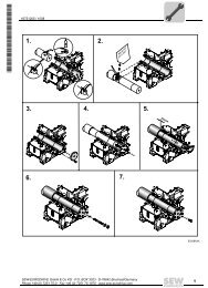
00755BXX<br />
Figure 8: Example of correct shield connection with metal clamp (shield clamp) or metal<br />
cable gland<br />
Shielding can also be achieved by laying the cables in grounded sheet metal<br />
ducts or metal pipes. In this case, the power cables and control cables should<br />
be routed separately.<br />
The unit is grounded via the connector for 24 V / 240 V voltage supply.<br />
22 <strong>System</strong> <strong>Manual</strong> – DOP11A <strong>Operator</strong> <strong>Terminal</strong>s
4.2 UL compliant installation<br />
<strong>System</strong> <strong>Manual</strong> – DOP11A <strong>Operator</strong> <strong>Terminal</strong>s<br />
Installation<br />
UL compliant installation<br />
Note the following points for UL compliant installation:<br />
Use only copper conductors with a temperature range of 60 / 75 °C as connection<br />
cables.<br />
4.3 Connection of basic unit DOP11A-10 to DOP11A-50<br />
Voltage supply<br />
Electrical connection according to the methods described in class 1, paragraph 2 (article<br />
501-4(b) according to National Electric Code NFPA70).<br />
Use only tested units with a limited output voltage (V max = DC 30 V) limited output<br />
current (I ≤ 8 A) as an external DC 24 V voltage source.<br />
UL certification does not apply to operation in voltage supply systems with a nonearthed<br />
star point (IT systems).<br />
Ensure correct polarity when connecting the terminal. Incorrect polarity will damage the<br />
unit.<br />
Make sure that the operator terminal and the controller system have the same electrical<br />
grounding (reference voltage value). Communication errors may occur if this is not the<br />
case.<br />
4<br />
23
Installation<br />
4 Connection to a PC<br />
4.4 Connection to a PC<br />
DOP 11A-10, DOP11A-20<br />
& DOP11A-40 DOP 11A-30<br />
Voltage supply DOP11A-10 to DOP11A-40 Voltage supply DOP11A-50<br />
(AC 100 - 240 V)<br />
53031AXX 53630AXX<br />
[1] Ground<br />
[2] 0 V<br />
[3] +24 V<br />
[1] [2] [3] [3] [2]<br />
Figure 9: Connection to a PC<br />
PCS11A<br />
RS-232 RS-232<br />
Programming of the operator terminal takes place via the HMI-Builder software.<br />
You need the PCS11A communication cable to program the operator terminal.<br />
24 <strong>System</strong> <strong>Manual</strong> – DOP11A <strong>Operator</strong> <strong>Terminal</strong>s<br />
[1]<br />
DOP11A<br />
The power must be switched off when connecting the units.<br />
DOP 11A-50<br />
[1]<br />
53040AXX
<strong>System</strong> <strong>Manual</strong> – DOP11A <strong>Operator</strong> <strong>Terminal</strong>s<br />
Installation<br />
RS-485 connection (DOP11A-10 and DOP11A-30 only)<br />
4.5 RS-485 connection (DOP11A-10 and DOP11A-30 only)<br />
Wiring diagram RS-485 interface<br />
Control unit<br />
/Controller inhibit<br />
CW/Stop*<br />
CCW/Stop*<br />
Enable/Rapid stop*<br />
n11/n21*<br />
n12/n22*<br />
Ref. X13:DIØØ...DIØ5<br />
+24V output<br />
Ref. potential bi nary signals<br />
RS-485 +<br />
RS-485 -<br />
Shield plate or<br />
shield clamp<br />
Figure 11: Pin assignment DOP11A-30<br />
You can connect up to 31 MOVIDRIVE ® units to one operator terminal with the RS-485<br />
interface.<br />
Connection of the DOP11A to a MOVIDRIVE ® frequency inverter directly via RS-485:<br />
DOP11A-10 via 25-pin Sub-D connector<br />
DOP11A-30 via Phoenix plug-in terminal strip<br />
RS-485<br />
Figure 10: RS-485 connection<br />
X13:<br />
DIØØ 1<br />
DIØ1 2<br />
DIØ2 3<br />
DIØ3 4<br />
DIØ4 5<br />
DIØ5 6<br />
DCOM** 7<br />
VO 24 8<br />
DGND 9<br />
ST11 10<br />
ST12 11<br />
.<br />
.<br />
.<br />
.<br />
.<br />
/Controller inhibit<br />
CW/Stop*<br />
CCW/Stop*<br />
Enable/Rapid stop*<br />
n11/n21*<br />
n12/n22*<br />
Ref. X13:DIØØ...DIØ5<br />
+24V output<br />
Ref. potential bi nary signals<br />
RS-485 +<br />
RS-485 -<br />
X13:<br />
DIØØ 1<br />
DIØ1 2<br />
DIØ2 3<br />
DIØ3 4<br />
DIØ4 5<br />
DIØ5 6<br />
DCOM ** 7<br />
VO24 8<br />
DGND 9<br />
ST11 10<br />
ST12 11<br />
DOP11A-30<br />
MOVIDRIVE® MOVIDRIVE® DOP11A-30<br />
Control unit<br />
Shield plate or<br />
shield clamp<br />
.<br />
.<br />
.<br />
.<br />
.<br />
53475AXX<br />
DGND<br />
RS485 -<br />
RS485 +<br />
4<br />
3<br />
2<br />
1<br />
53760AEN<br />
4<br />
25
Installation<br />
4 RS-485 connection (DOP11A-10 and DOP11A-30 only)<br />
Control unit<br />
/Controller inhibit<br />
CW/Stop*<br />
CCW/Stop*<br />
Enable/Rapid stop*<br />
n11/n21*<br />
n1 2/n2 2*<br />
Ref. X13:DIØØ...DIØ5<br />
+24V output<br />
Ref. potential bi nary s ignals<br />
RS-485 +<br />
RS-485 -<br />
Figure 12: Pin assignment DOP11A-10<br />
Cable specification Use a 2x2 core twisted and shielded copper cable (data transmission cable with braided<br />
copper shield). The cable must meet the following specifications:<br />
– Core cross section 0.5 ... 0.75 mm2 (AWG 20 ... 18)<br />
– Cable resistance 100 ... 150 Ω at 1 MHz<br />
– Capacitance per unit length ≤ 40 pF/m (12 pF/ft) at 1 kHz<br />
The following cable is suitable, for example:<br />
– Lappkabel, UNITRONIC ® BUS CAN, 2 x 2 x 0.5 mm2 .<br />
Shielding Apply shield on both ends over large area at the controller electronics shield clamp and<br />
in the housing of the 25-pin Sub-D connector of the operator terminal.<br />
Do not connect the shield ends with DGND!<br />
Line length The permitted total cable length is 200 m (660 ft).<br />
Terminating<br />
resistor<br />
Shield plate or<br />
shield clamp<br />
X13:<br />
DI ØØ<br />
DI Ø1<br />
DI Ø2<br />
DI Ø3<br />
DI Ø4<br />
DI Ø5<br />
DCOM**<br />
VO 24<br />
DGND<br />
ST11<br />
ST 12<br />
1<br />
2<br />
3<br />
4<br />
5<br />
6<br />
7<br />
8<br />
9<br />
10<br />
11<br />
MOVIDRIVE®<br />
Conne ct ju mper be tw een 6-19<br />
MOVIDRIVE®<br />
to activate bus termination.<br />
Control unit<br />
/Controller inhibit<br />
CW/Stop*<br />
CCW/Stop*<br />
Enable/Rapid stop*<br />
n11/n21*<br />
n12/n22*<br />
Ref. X13:DIØØ...DIØ5<br />
+24V output<br />
Ref. potential binary signals<br />
RS-485 +<br />
RS-485 -<br />
Shield plate or<br />
shield clamp<br />
X13:<br />
DIØØ<br />
DIØ1<br />
DIØ2<br />
DIØ3<br />
DIØ4<br />
DIØ5<br />
DCOM**<br />
VO24<br />
53762AEN<br />
The controller and the UWS11A interface converter come equipped with dynamic terminating<br />
resistors. Do not connect any external terminating resistors in this instance!<br />
26 <strong>System</strong> <strong>Manual</strong> – DOP11A <strong>Operator</strong> <strong>Terminal</strong>s<br />
DGND<br />
ST11<br />
ST12<br />
1<br />
2<br />
3<br />
4<br />
5<br />
6<br />
7<br />
8<br />
9<br />
10<br />
11<br />
DOP11A-10<br />
RS-422 / 485 25 pin D-sub female<br />
13 7<br />
2 1<br />
25<br />
14
<strong>System</strong> <strong>Manual</strong> – DOP11A <strong>Operator</strong> <strong>Terminal</strong>s<br />
Installation<br />
RS-485 connection (DOP11A-10 and DOP11A-30 only)<br />
If the DOP11A-10 operator terminal is connected with the frequency inverters via RS-<br />
485, you will have to activate the terminating resistor in the 25-pin Sub-D connector of<br />
the DOP11A-10 (jumper between pin 6 and pin 19) in case the operator terminal is the<br />
first or last station.<br />
There must not be any difference of potential between the units connected using the RS-<br />
485. Take suitable measures to avoid a potential displacement, e.g. by connecting the<br />
unit ground connectors using a separate lead.<br />
4<br />
27
Installation<br />
4 Connection RS-422 via UWS11A<br />
4.6 Connection RS-422 via UWS11A<br />
MOVIDRIVE®<br />
Control unit<br />
/Controller inhibit<br />
CW/Stop*<br />
CCW/Stop*<br />
Enable/Rapid stop*<br />
n11/n21*<br />
n12/n22*<br />
Ref. X13:DIØØ...DIØ5<br />
+24V output<br />
Ref. potential binary signals<br />
RS-485 +<br />
RS-485 -<br />
Figure 14: Pin assignment UWS11A<br />
RS-485<br />
connection<br />
Shield plate or<br />
shield clamp<br />
X13:<br />
DIØØ<br />
DIØ1<br />
DIØ2<br />
DIØ3<br />
DIØ4<br />
DIØ5<br />
DCOM**<br />
VO24<br />
Connecting the DOP11A to a MOVIDRIVE ® frequency inverter via UWS11A.<br />
PCC11A<br />
Figure 13: Connection via serial connection (UWS11A)<br />
DGND<br />
ST11<br />
ST12<br />
1<br />
2<br />
3<br />
4<br />
5<br />
6<br />
7<br />
8<br />
9<br />
10<br />
11<br />
MOVIDRIVE®<br />
Control unit<br />
/Controller inhibit<br />
CW/Stop*<br />
CCW/Stop*<br />
Enable/Rapid stop*<br />
n11/n21*<br />
n12/n22*<br />
Ref. X13:DIØØ...DIØ5<br />
+24V output<br />
Ref. potential bBinary signals<br />
RS-485 +<br />
RS-485 -<br />
Shield plate or<br />
shield clamp<br />
X13:<br />
DIØØ<br />
DIØ1<br />
DIØ2<br />
DIØ3<br />
DIØ4<br />
DIØ5<br />
DCOM**<br />
VO24<br />
UWS11A<br />
53288AXX<br />
See section 4.5, "Connection RS-485 (DOP11A-10 and DOP11A-30 only)" for the cable<br />
specification.<br />
28 <strong>System</strong> <strong>Manual</strong> – DOP11A <strong>Operator</strong> <strong>Terminal</strong>s<br />
DGND<br />
ST11<br />
ST12<br />
1<br />
2<br />
3<br />
4<br />
5<br />
6<br />
7<br />
8<br />
9<br />
10<br />
11<br />
RS-485<br />
UWS11A<br />
X2: RS-232<br />
UWS<br />
.....<br />
1 +24 VDC<br />
2 GND<br />
3 RS +<br />
4 RS –<br />
5 GND<br />
53763AEN
4.7 Connection PFE11A ETHERNET option<br />
<strong>System</strong> <strong>Manual</strong> – DOP11A <strong>Operator</strong> <strong>Terminal</strong>s<br />
Installation<br />
Connection PFE11A ETHERNET option<br />
Connection of DOP11A with PFE11A Ethernet option card (not available with DOP11A-<br />
10) to a PC for programming and remote maintenance via Ethernet and TCP / IP.<br />
Switch /<br />
Hub<br />
Figure 15: Connection PFE11A ETHERNET option<br />
There are four LEDs on the front of the PFE11A expansion card.<br />
These LEDs have the following functions:<br />
Cable specification Use a shielded standard Ethernet cable with shielded RJ45 connectors and cables<br />
according to specification CAT5. The maximum cable length is not to exceed 100 m<br />
(300ft.).<br />
LAN<br />
Uplink<br />
PFE11A<br />
DOP11A<br />
The following cable is suitable, for example:<br />
– Lappkabel, UNITRONIC ® LAN UTP BS flexible 4 x 2 x 26 AWG<br />
53331AXX<br />
Function Color Description<br />
SEL Yellow This LED will light up if there is a contact between terminal processor and expansion<br />
card connection.<br />
TxD Yellow This LED lights up when you send ETHERNET data.<br />
RxD Yellow This LED lights up when you receive ETHERNET data.<br />
LINK Green This LED lights up when the ETHERNET cable (twisted pair cable) has been<br />
connected correctly.<br />
You will find a description for determination of the Ethernet (MAC) address of the option<br />
card in section 5.2, in the paragraph "Configuration mode (SETUP)".<br />
4<br />
29
Installation<br />
4 Connection PFP11A PROFIBUS-DP option<br />
4.8 Connection PFP11A PROFIBUS-DP option<br />
Data exchange of a PLC with a DOP11A via PFP11A and PROFIBUS DP. (See section<br />
3.8 "Accessories and options" for a description of the PFP11A.)<br />
DOP11A<br />
Figure 16: Connection PFP11A PROFIBUS option<br />
1<br />
ON<br />
PFP11A<br />
Figure 17: Connection PFP11A PROFIBUS option<br />
PROFIBUS-DP<br />
P R O F I<br />
PROCESS FIELD BUS<br />
B U S<br />
53043AXX<br />
53632AXX<br />
[1] 9-pin Sub-D socket<br />
[2] PROFIBUS terminating resistor<br />
If the panel is located at the beginning or end of a PROFIBUS segment and if only one PROFIBUS<br />
cable is connected to the panel, you will either have to activate the connector in the terminating<br />
resistor (if present) or set the switch on the PFP11A card to "On".<br />
Never activate both terminating resistors in the connector and card at the same time!<br />
[3] The LEDs on the expansion card have the following functions:<br />
1:ERR Red Displays configuration or communication errors.<br />
The LED lights up red until the unit is configured and indicates a time violation.<br />
2:PWR Green Displays a voltage supply with DC 5 V.<br />
3:DIA Green Displays a diagnostics error in the PROFIBUS network.<br />
Is not used by the panel.<br />
[4] The PROFIBUS station address is set using two rotary switches.<br />
The GSD type files required for configuration of the PROFIBUS are available on the<br />
HMI-Builder software ROM or at www.sew-eurodrive.de in the Software tab.<br />
30 <strong>System</strong> <strong>Manual</strong> – DOP11A <strong>Operator</strong> <strong>Terminal</strong>s<br />
1<br />
2<br />
3<br />
9<br />
8<br />
7<br />
6<br />
0<br />
5<br />
1<br />
2<br />
4<br />
Term. Stn.<br />
MSB LSB<br />
[1] [2] [3] [4]<br />
3<br />
9<br />
8<br />
7<br />
6<br />
0<br />
5<br />
1<br />
2<br />
4<br />
no.<br />
3<br />
SPS<br />
®
<strong>System</strong> <strong>Manual</strong> – DOP11A <strong>Operator</strong> <strong>Terminal</strong>s<br />
Installation<br />
Connection to a Siemens S7 via MPI and PCM11A<br />
Cable specification Use a two-core, twisted and shielded copper cable to PROFIBUS specification for<br />
conductor type A to EN 50170 (V2).<br />
The following cable is suitable, for example:<br />
– Lappkabel, UNITRONIC ® BUS L2/F.I.P.<br />
4.9 Connection to a Siemens S7 via MPI and PCM11A<br />
DOP11A<br />
RS-232<br />
PCM11A<br />
Figure 18: Connection to a Siemens S7 via MPI and PCM11A<br />
MPI<br />
SIMATIC S7<br />
53044AXX<br />
4<br />
31
I<br />
Startup<br />
5 Initial operation<br />
0<br />
5 Startup<br />
5.1 Initial operation<br />
General startup<br />
instructions<br />
Preliminary work<br />
and resources<br />
It is essential to comply with the safety notes during startup!<br />
Prerequisite<br />
Requirement for a successful startup is the correct electrical connection of the operator<br />
terminal.<br />
The functions described in this section will enable users to upload a project to the operator<br />
terminal and establish the unit in the necessary communication pathways.<br />
Do not use the DOP11A operator terminals as safety devices for industrial applications.<br />
Use monitoring systems or mechanical protection devices as safety features to avoid<br />
possible damage to property or injury to people.<br />
Check the installation.<br />
Prevent unintentional start of motor via connected frequency inverter by suitable<br />
measures.<br />
– Remove the electronics input X13.0/controller inhibit in MOVIDRIVE ® or<br />
– clear the supply voltage (24 V back-up voltage still has to be present)<br />
– Remove terminals "CW operation" and "Enable" in MOVITRAC ® 07<br />
Furthermore, additional safety precautions must be taken depending on the application<br />
to avoid injury to people and damage to machinery.<br />
Connect operator terminal with corresponding cable to MOVIDRIVE ® or<br />
MOVITRAC ® 07.<br />
PCC11A<br />
UWS11A<br />
RS485<br />
Figure 19: Connection between operator terminal and MOVIDRIVE ® MDX60B/61B<br />
53243AXX<br />
Connect operator terminal with the PC via PCS11A (RS-232) programming cable.<br />
<strong>Operator</strong> terminal and PC must be de-energized when you do this, otherwise undefined<br />
states may be adopted. Turn on PC and start HMI-Builder configuration software;<br />
install software if not present yet.<br />
32 <strong>System</strong> <strong>Manual</strong> – DOP11A <strong>Operator</strong> <strong>Terminal</strong>s
<strong>System</strong> <strong>Manual</strong> – DOP11A <strong>Operator</strong> <strong>Terminal</strong>s<br />
PCS11A<br />
Figure 20: Connection between PC and operator terminal<br />
Startup<br />
Initial operation<br />
Start 24 V supply for operator term inal and connected frequency inverters.<br />
Units are delivered without loaded project.<br />
Units with membrane keypad (DOP11A-10, DOP11A-20 and DOP11A-40) will report<br />
the following information when they are initially taken into operation:<br />
53253AXX<br />
Figure 21: Initial image DOP11A-10 in delivery state<br />
53250AXX<br />
Units with membrane keypad DOP11A-10, DOP11A-20 and DOP11A-40 will remain in<br />
[Edit] / [Transfer] mode. You will find a description of the individual functions in the<br />
following section.<br />
I<br />
0<br />
5<br />
33
I<br />
Startup<br />
5 Initial operation<br />
0<br />
The touchscreen units DOP11A-30 and DOP11A-50 report that no inverter or PLC<br />
communication driver have been loaded.<br />
Driver2:<br />
PLC1:<br />
PLC2:<br />
DOP11A-50<br />
No driver<br />
Figure 22: Initial screen DOP11A-50 in delivery state<br />
53602AXX<br />
34 <strong>System</strong> <strong>Manual</strong> – DOP11A <strong>Operator</strong> <strong>Terminal</strong>s<br />
OK
5.2 <strong>Operator</strong> terminal functions<br />
The keyboard in<br />
the terminal<br />
<strong>System</strong> <strong>Manual</strong> – DOP11A <strong>Operator</strong> <strong>Terminal</strong>s<br />
Startup<br />
<strong>Operator</strong> terminal functions<br />
This chapter describes the different modes in the operator terminal, the keyboard and<br />
the information page in the terminal.<br />
MAIN<br />
7<br />
ABCD<br />
4<br />
MNOP<br />
1YZ!?<br />
8<br />
EFGH<br />
5<br />
QRST<br />
9<br />
IJKL<br />
6 UVWX<br />
- 0 .<br />
+/*=<br />
2<br />
C1 - C4<br />
° %#:<br />
LIST<br />
PREV ACK<br />
3 ()<br />
´ @ ,<br />
[1] Integrated function keys (not DOP11A-10)<br />
[2] Arrow keys<br />
[3] Alphanumeric keys<br />
52609AXX<br />
Alphanumeric keys From the alphanumeric keyboard the following characters can be entered in dynamic<br />
text and numerical objects during run mode in the operator terminal.<br />
0-9<br />
A-Z<br />
a-z<br />
! ? < > ( ) + / * = º % # : ’ @<br />
National characters<br />
[1]<br />
[2]<br />
[3]<br />
I<br />
0<br />
5<br />
35
I<br />
Startup<br />
5 <strong>Operator</strong> terminal functions<br />
0<br />
Reserved<br />
characters<br />
Numeric values are entered by pressing the respective key once.<br />
Enter capital letters (A to Z) by pressing the respective key two to five times.<br />
Enter lower case letters (a to z) by pressing the respective key six to nine times.<br />
The delay time interval between pressing can be set. If the key is not pressed within the<br />
delay time interval the cursor moves to the next position.<br />
Enter national characters by pressing key (C1C4) two to nine times. This option<br />
offers characters that are not included in the standard character set of the alphanumeric<br />
terminal keyboard.<br />
The ASCII characters 0-32 (Hex 0-1F) and 127 are reserved for internal terminal<br />
functions and must not be used in projects or files in the terminal. The characters are<br />
used as control characters.<br />
Arrow keys Use the arrow keys to move the cursor in a menu or dialog.<br />
Built-in function<br />
keys<br />
You cannot enter characters via the keyboard of the DOP11A-10 terminal because it is<br />
not equipped with alphanumeric keys.<br />
You can use all characters of the selected character set in the HMI-Builder except those<br />
characters reserved for static text. Enter the required character by pressing the<br />
+ key combination on the numeric keyboard of the PC; then enter the<br />
character code. You select the used character set in the HMI-Builder.<br />
Not all the keys are available on all terminals.<br />
Key Description<br />
Enter key Use the ENTER key to confirm the setting made and to go to the next line or level.<br />
Use this key to return to the previous block.<br />
Use this key to to bring up the alarm list.<br />
Use this key to acknowledge alarms in the alarm list.<br />
Use this key to jump to block 0 in run mode.<br />
Use this key to delete characters to the left of the cursor.<br />
When the main block (block number 0) was displayed, the key will not work<br />
because the block history is deleted once the main block has been reached.<br />
36 <strong>System</strong> <strong>Manual</strong> – DOP11A <strong>Operator</strong> <strong>Terminal</strong>s
<strong>System</strong> <strong>Manual</strong> – DOP11A <strong>Operator</strong> <strong>Terminal</strong>s<br />
Startup<br />
<strong>Operator</strong> terminal functions<br />
Key combinations The terminal has key combinations for the following functions:<br />
Key combination Function<br />
Toggle between SETUP and RUN.<br />
Hold this key combination pressed during startup to activate<br />
the mode for downloading the system program (see section 4,<br />
"Installation").<br />
Open information window.<br />
Hold the key combination pressed during start up to activate<br />
the self-test function.<br />
+<br />
<strong>Terminal</strong> type<br />
Function<br />
Sysload Self-test Toggle between<br />
SETUP and RUN<br />
Diagnostics<br />
window<br />
DOP11A-10 + + +<br />
+<br />
+<br />
DOP11A-20 + + + <br />
+<br />
DOP11A-40 + + + <br />
I<br />
0<br />
5<br />
37
I<br />
Startup<br />
5 <strong>Operator</strong> terminal functions<br />
0<br />
Switches on<br />
DOP11A-30 and<br />
DOP11A-50 terminals<br />
RUN and SETUP<br />
operating modes<br />
Interrupt power supply to terminal to call up individual modes for DOP11A-30 and<br />
DOP11A-50.<br />
Turn the rotary switch on the side or back of the terminal to the position shown in the<br />
following table. You can now turn on the power supply once again.<br />
The terminal has two operation modes.<br />
Configuration mode (SETUP): All basic settings are made in this mode, such as<br />
selection of controller system and menu language.<br />
Run-time mode (RUN): This mode is for running the application.<br />
Transfer Here you manually set the terminal to transfer mode. When the terminal is in transfer<br />
mode it is possible to transfer projects between the terminal and the programming software.<br />
By using the automatic terminal switching function [RUN] / [TRANSFER] in the<br />
programming software, the software automatically sets the terminal to transfer mode.<br />
Switching between<br />
modes<br />
Switch position Function<br />
0 Run mode (RUN, standard operation)<br />
1 Sysload<br />
2 Calibrate touch<br />
3 Cursor<br />
4 Configuration mode (SETUP)<br />
5 Transfer mode, TRANSFER<br />
8 Activates self-test function<br />
9 Erases the clock memory<br />
Switch between RUN and SETUP<br />
Press and simultaneously to enter configuration mode (SETUP). You can<br />
now press any key when the start-up menu is shown to enter the configuration mode,<br />
SETUP. To return to run mode, press and .<br />
In DOP11A-30 and DOP11A-50 you set the switch on the side/back of the terminal in<br />
position 4 to access the configuration mode (Setup). The switch should be in position 0<br />
for standard operation.<br />
38 <strong>System</strong> <strong>Manual</strong> – DOP11A <strong>Operator</strong> <strong>Terminal</strong>s
Configuration<br />
mode (SETUP)<br />
<strong>System</strong> <strong>Manual</strong> – DOP11A <strong>Operator</strong> <strong>Terminal</strong>s<br />
Startup<br />
<strong>Operator</strong> terminal functions<br />
This section contains a description of those functions that cannot be carried out with the<br />
HMI-Builder.<br />
Erasing the memory<br />
In the [setup] menu in the terminal there is a function [Erase Memory]. Use this function<br />
to erase the application memory of the terminal. All blocks and definitions for alarms,<br />
time channels, function keys and system signals are erased.<br />
Parameters Description<br />
Enter key Memory is erased. The configuration menu is shown automatically<br />
when the erasure is completed.<br />
Return to previous level without erasing the memory.<br />
When the memory is erased all data stored in the terminal will be lost. The language<br />
selection parameter is not affected by this function. All other parameters will be erased<br />
or given their default values.<br />
Contrast setting<br />
<strong>Operator</strong> terminal Contrast setting<br />
DOP11A-10 Contrast is set with a rotary regulator on the back of the terminal.<br />
DOP11A-20 Contrast is set in operating mode by jumping to system block 997. The monitor will<br />
DOP11A-30<br />
DOP11A-40<br />
be brighter by pressing the function key. You reduce brightness by pressing the<br />
function key. Return to the previous level by pressing .<br />
DOP11A-50 The color intensity of the display can be controlled through a data register and the<br />
[DIM] command, specified in the command line under [Setup] / [<strong>System</strong> signals] of<br />
the programming software.<br />
The contrast depends on the ambient temperature. If the terminal is programmed at a<br />
room temperature far below the one at the installation site, you will have to adjust the<br />
contrast at the actual ambient temperature after 15 - 30 minutes.<br />
I<br />
0<br />
5<br />
39
I<br />
Startup<br />
5 <strong>Operator</strong> terminal functions<br />
0<br />
Determining the Ethernet (MAC) address:<br />
The Ethernet address of the PFE11A option card is displayed in configuration mode<br />
(SETUP). Use the key combination (DOP11A-20 and DOP11A-40) or<br />
switch position 4 (DOP11A-30 and DOP11A-50) to enter configuration mode.<br />
The physical Ethernet address is displayed in the menu item [Expansion Cards - Slot 1<br />
- PFE].<br />
Run mode (RUN) The application is executed in run mode. Block 0 will automatically be shown on the<br />
display when changing to run mode.<br />
The built-in keyboard in the terminal is used to highlight and change values in run mode.<br />
If a communication error occurs between the terminal and the controller system, an error<br />
message will be shown on the display. The terminal starts automatically once the<br />
communication is resumed. If you press an I/O key combination while a communication<br />
error is present, the combination will be stored in the terminal buffer and transferred to<br />
the controller system once communication resumes.<br />
The terminal clock can continuously send data to a register in the controller to activate<br />
a monitoring function. The controller can use this monitoring function to detect a possible<br />
communication error. The controller system checks if the register is updated, and if not<br />
an alarm indicating a communication error is activated in the controller system.<br />
The functional principle of individual objects and functions in operating mode will be<br />
explained in connection with the description of the respective objects and functions.<br />
Setting the realtime<br />
clock<br />
The real-time clock of the terminal is set in the [Setup] menu under [Date / Time.].<br />
Select the option [Set terminal clock]. The date and time will now be displayed. Press<br />
to change the setting. Enter the required date and time. Move the cursor with the<br />
arrow keys in editing mode. Press to return to the previous menu or cancel the<br />
setting before you press the Enter key.<br />
The real-time clock can also be set in run mode through a maneuverable clock object<br />
and during the transfer of projects from a PC to the terminal.<br />
A digital signal set by a command can let operators know when it is time to change the<br />
battery for the real-time clock.<br />
40 <strong>System</strong> <strong>Manual</strong> – DOP11A <strong>Operator</strong> <strong>Terminal</strong>s
<strong>System</strong> <strong>Manual</strong> – DOP11A <strong>Operator</strong> <strong>Terminal</strong>s<br />
Startup<br />
<strong>Operator</strong> terminal functions<br />
Information page The terminal contains an information page. The information page is activated by pressing<br />
the key combination and simultaneously in run mode. A function or<br />
touch key can also be used or configured to call up the information page.<br />
The current terminal, system program version and hardware version are shown at the<br />
top of the information page.<br />
Parameters Description<br />
STARTS Number of terminals starts<br />
RUN Operating time of the terminal<br />
CFL Number of hours the backlighting has been switched on.<br />
32°C MIN: 21 MAX: 38 Current operating temperature, lowest and highest temperature measure-<br />
(example)<br />
ment<br />
DYNAMIC MEMORY Available RAM memory (working memory) in number of bytes.<br />
FLASH MEM PROJ Available Flash memory (project memory) in number of bytes.<br />
FLASH MEM BACK Reserved<br />
FLASH CACHEHITS Percent of block / allocation cache hits in the file system.<br />
FLASH ALLOCS Maximum percent of used or active allocations per block in the file system.<br />
DRIVER 1 Current driver and driver version.<br />
DIGITAL I/Os The number of digital signals linked to controller system 1 continuously<br />
monitored (STATIC) and the number in the current block (MONITOR).<br />
ANALOG I/Os The number of analog signals linked to controller system 1 continuously<br />
monitored (STATIC) and the number in the current block (MONITOR).<br />
I/O POLL The time in ms between two readings of the same signal in controller 1.<br />
PKTS The number of signals in each package transferred between the terminal<br />
and controller 1.<br />
TOUT1 The number of timeouts in communication with controller 1.<br />
CSUM1 The number of checksum errors in communication with controller 1.<br />
BYER The number of byte errors in the communication.<br />
DRIVER 2 Current driver and driver version. The parameters for Driver 2 are only<br />
shown if controller 2 is defined in the project.<br />
DIGITAL I/Os The number of digital signals linked to controller 2 continuously monitored<br />
(STATIC) and the number in the current block (MONITOR).<br />
ANALOG I/Os The number of analog signals linked to controller 2 continuously monitored<br />
(STATIC) and the number in the current block (MONITOR).<br />
I/O POLL The time in ms between two readings of the same signal in controller 2.<br />
PKTS The number of signals in each package transferred between the terminal<br />
and controller 2.<br />
TOUT2 The number of timeouts in communication with controller 2.<br />
CSUM2 The number of checksum errors in communication with controller 2.<br />
1 / 2 / 3 Current port for FRAME, OVERRUN and PARITY.<br />
1 = RS-422 port, 2 = RS-232 port and 3 = RS-485 port.<br />
FRAME The number of frame errors in each port.<br />
OVERRUN The number of overrun errors in each port.<br />
PARITY The number of parity errors in each port.<br />
Joystick function Applicable for DOP11A-20 and DOP11A-40 only.<br />
This function makes it possible to use the arrow keys as function keys. Enter the command<br />
"AK" and an address in the command line under [system signals]. Example:<br />
"AKM100" (command AK and memory cell M100).<br />
I<br />
0<br />
5<br />
41
I<br />
Startup<br />
5 <strong>Operator</strong> terminal functions<br />
0<br />
Figure 23: <strong>System</strong> signals<br />
53107AEN<br />
Memory cell M100 is the enable signal and the following four memory cells have<br />
functions according to the following control block:<br />
Memory cell Description<br />
Mn0 Active = Joystick function. Disabled = normal function.<br />
Mn1 LEFT ARROW<br />
Mn2 DOWN ARROW<br />
Mn3 UP ARROW<br />
Mn4 RIGHT ARROW<br />
If you press on an arrow when the enable signal is on, the memory cell corresponding<br />
to the key you press will be set to one. When the enable signal is set to one, the arrow<br />
keys will not have their normal functions.<br />
42 <strong>System</strong> <strong>Manual</strong> – DOP11A <strong>Operator</strong> <strong>Terminal</strong>s
<strong>System</strong> <strong>Manual</strong> – DOP11A <strong>Operator</strong> <strong>Terminal</strong>s<br />
Startup<br />
<strong>Operator</strong> terminal functions<br />
Example Use the following example to toggle between joystick function and normal function.<br />
Perform the following steps:<br />
Use the DEMO driver.<br />
Enter the text "AKM1" under [system signals] / [commands].<br />
Generate a text block.<br />
Enter the static text "JOYSTICK."<br />
Create a digital object with the following settings:<br />
– Digital signal: M1<br />
– Text 0: OFF<br />
– Text 1: ON<br />
– Activate input: YES<br />
Create four additional digital objects to observe the memory contents of M2, M3, M4<br />
and M5.<br />
Display of text block according to sample settings:<br />
JOYSTICK # - - -<br />
M2#<br />
M3 #<br />
M4 #<br />
M5 #<br />
I<br />
0<br />
5<br />
43
I<br />
Operation and Service<br />
6 Project transfer with PC and HMI-Builder<br />
0<br />
6 Operation and Service<br />
6.1 Project transfer with PC and HMI-Builder<br />
You need the HMI-Builder software for starting up the operator terminal with your PC.<br />
1. Start the HMI-Builder program.<br />
2. Select the language in the [Settings] / [Menu language] selection field.<br />
10375AEN<br />
10376AEN<br />
44 <strong>System</strong> <strong>Manual</strong> – DOP11A <strong>Operator</strong> <strong>Terminal</strong>s
<strong>System</strong> <strong>Manual</strong> – DOP11A <strong>Operator</strong> <strong>Terminal</strong>s<br />
Operation and Service<br />
Project transfer with PC and HMI-Builder<br />
3. Use the [File] / [Open] function to open the project file you would like to transmit to<br />
the operator terminal.<br />
4. In the selection field [Transfer] / [Comm. settings], select the communication<br />
connection [Use serial transfer] and enter the necessary parameters:<br />
Serial transfer when using the PCS11A programming cable.<br />
Enter following information:<br />
Communication port of the PC (e.g. Com1)<br />
Baud rate (default 57,600)<br />
Timeout period (free entry, default 10,000 ms)<br />
Number of retries in case of communication problems (default 3)<br />
I<br />
0<br />
10377AEN<br />
10378AEN<br />
6<br />
45
I<br />
Operation and Service<br />
6 Project transfer with PC and HMI-Builder<br />
0<br />
If a project is transferred to the terminal for the first time, the transfer will take place via<br />
serial connection and the PCS11A programming cable.<br />
10379AEN<br />
5. The project can now be transferred to the terminal with the selection field [Transfer]<br />
/ [Project].<br />
The following functions are active as standard and must remain in this setting.<br />
Test project on send<br />
Send complete project<br />
Automatic terminal RUN/TRANSFER switching<br />
Check terminal version<br />
Download of files takes place after activation of [Send] button.<br />
46 <strong>System</strong> <strong>Manual</strong> – DOP11A <strong>Operator</strong> <strong>Terminal</strong>s
<strong>System</strong> <strong>Manual</strong> – DOP11A <strong>Operator</strong> <strong>Terminal</strong>s<br />
Operation and Service<br />
Project transfer with PC and HMI-Builder<br />
10381AEN<br />
The following steps will be executed one after the other:<br />
Switching the terminal to transfer mode (TRANSFER)<br />
Transfer of download driver for inverter and PLC<br />
Transfer of project data<br />
Switching the terminal to RUN mode<br />
The individual steps will be displayed during transfer in the terminal display.<br />
After completed transfer, exit the dialog window with the [Exit] button and close the<br />
HMI-Builder.<br />
I<br />
0<br />
6<br />
47
I<br />
Operation and Service<br />
6 Operating display at unit start<br />
0<br />
6.2 Operating display at unit start<br />
[1]<br />
[2]<br />
[3]<br />
[4]<br />
[5]<br />
[6]<br />
Firmware: V1.00<br />
[1] Firmware version of the operator terminal<br />
[2] Status of the boot process<br />
e.g.:<br />
PROJECT STATUS<br />
TCP/IP ADDRESS<br />
CHECKING PLC 1<br />
CHECKING PLC 2<br />
...<br />
[3] Communication driver loaded in Controller 1<br />
e.g.:<br />
DEMO<br />
SEW_MOVIDRIVE<br />
...<br />
[4] Communication driver loaded in Controller 2<br />
e.g.:<br />
DEMO<br />
SEW_MOVIDRIVE<br />
...<br />
[5] Communication status of Controller 1<br />
e.g.:<br />
NO CONNECTION<br />
DEMO<br />
MOVITRAC 07<br />
MOVIDRIVE A<br />
MOVIDRIVE B<br />
...<br />
[6] Communication status of Controller 2<br />
e.g.:<br />
NO CONNECTION<br />
DEMO<br />
MOVITRAC 07<br />
MOVIDRIVE A<br />
MOVIDRIVE B<br />
...<br />
[7] Version of operator terminal boot routine<br />
DOP11A-40<br />
Status: Booting filesystem<br />
Driver1: SEW_MOVIDRIVE<br />
Driver2: DEMO<br />
PLC1: MOVIDRIVE B<br />
PLC2: DEMO<br />
Boot: V5.00<br />
53588AXX<br />
48 <strong>System</strong> <strong>Manual</strong> – DOP11A <strong>Operator</strong> <strong>Terminal</strong>s<br />
[7]
6.3 Error Messages<br />
Boot error (no inverter connected)<br />
<strong>System</strong> <strong>Manual</strong> – DOP11A <strong>Operator</strong> <strong>Terminal</strong>s<br />
Operation and Service<br />
Error Messages<br />
Errors in RUN mode will be displayed in the upper left hand corner of the display as error<br />
message.<br />
They are divided into two groups:<br />
Boot error (no inverter connected)<br />
Operation errors - Comm Errors (error list)<br />
Boot error "1: Comm Error 254" means: no communication with connected inverters.<br />
[1]<br />
[2]<br />
[3]<br />
1: Comm Error 254<br />
[1] Controller where the communication error occurs.<br />
e.g 1 or 2<br />
[2] Error type<br />
e.g. operation error - Comm Error<br />
[3] With RS-485 address:<br />
E.g.<br />
01 - 99<br />
254 (= Point to Point!)<br />
53590AXX<br />
I<br />
0<br />
6<br />
49
I<br />
Operation and Service<br />
6 Error Messages<br />
0<br />
Operation errors - Comm Errors (error list)<br />
Message from operator<br />
terminal<br />
Error code Description<br />
no error 00 00 No error<br />
invalid parameter 00 10 Illegal parameter index<br />
fct. not implement 00 11 Function / parameter not implemented;<br />
Controller does not know parameter addres sed by the operator terminal. Check correct<br />
selection of MOVILINK ® driver. Individual parameters of the MOVITRAC ® 07,<br />
MOVIDRIVE ® A and MOVIDRIVE ® B controllers are slightly different.<br />
Another reason for this error may be the controller firmware. Recently added parameters<br />
may not be included in older versions of the unit firmware.<br />
read only access 00 12 Read access only<br />
No write access to addressed parameter. Deactivate [Activate input] function in<br />
project of operator terminal.<br />
param. lock active 00 13 Parameter lock is active<br />
The [Parameter block] function was activa ted via parameter P803 in the addressed<br />
controller. Set parameter P803 to "OFF" by using the controller keypad or the PC<br />
software MOVITOOLS ® to deactivate the parameter lock.<br />
fact. set active 00 14 Factory setting is active<br />
Controller is performing a factory setting. Parameter change option is locked for a<br />
few seconds. Communication will be automatically reactivated once factory setting is<br />
complete.<br />
value too large 00 15 Value too large for parameter<br />
<strong>Operator</strong> terminal is trying to write a value to a parameter that is not within the permitted<br />
value range. Adapt the project of the operator terminal in the [Access] area to be<br />
within the limits of the minimum and maximum input values. You will find the respective<br />
limit values in the parameter list of the controller.<br />
value too small 00 16 Value too small for parameter<br />
<strong>Operator</strong> terminal is trying to write a value to a parameter that is not within the permitted<br />
value range. Adapt the project of the operator terminal in the [Access] area to be<br />
within the limits of the minimum and maximum input values. You will find the respective<br />
limit values in the parameter list of the controller.<br />
option missing 00 17 Required option card missing for this function / this parameter.<br />
system error 00 18 Error in system software of controller<br />
Contact SEW service.<br />
no RS485 access 00 19 Parameter access via RS-485 process interface on X13 only<br />
no RS485 access 00 1A Parameter access via RS-485 diagnostic interface only<br />
access protected 00 1B Parameter is access-protected<br />
No read or write access to this parameter; parameter not suitable for use in operator<br />
terminal.<br />
inhibit required 00 1C Controller inhibit required<br />
The addressed parameter can only be altere d with inhibited controller. Activate the<br />
controller inhibit status by removing the terminal X13.0 or via fieldbus (control word<br />
1/2 basic block = 01hex).<br />
incorrect value 00 1D Incorrect value<br />
Some parameters can only be programm ed to certain values. You will find the<br />
respective limit values in the parameter list of the controller.<br />
fact. set active 00 1E Factory setting was activated.<br />
not saved in EEPROM 00 1F Parameter was not saved in EEPROM<br />
Power-failure save failed.<br />
inhibit required 00 20 Parameter cannot be changed with enabled output stage<br />
The addressed parameter can only be altere d with inhibited inverter. Activate the<br />
controller inhibit status by removing the terminal X13.0 or via fieldbus (control word<br />
1/2 basic block = 01hex).<br />
50 <strong>System</strong> <strong>Manual</strong> – DOP11A <strong>Operator</strong> <strong>Terminal</strong>s
6.4 SEW electronics service<br />
<strong>System</strong> <strong>Manual</strong> – DOP11A <strong>Operator</strong> <strong>Terminal</strong>s<br />
Operation and Service<br />
SEW electronics service<br />
Send in for repair Please contact the SEW Electronics Service if a fault cannot be rectified.<br />
When contacting the SEW electronics service, always quote the digits of the unit<br />
designation so that our service personnel can assist you more effectively.<br />
Please provide the following information when sending the unit in for repair:<br />
Serial number ( → nameplate)<br />
Unit designation<br />
Brief description of the application<br />
Nature of the error<br />
Accompanying circumstances<br />
Your own presumption of what has happened<br />
Any unusual events preceding the problem, etc.<br />
I<br />
0<br />
6<br />
51
I<br />
Programming<br />
7 Creating a project<br />
0<br />
7 Programming<br />
7.1 Creating a project<br />
Basics This chapter describes the system structure of the terminal and its basic functions.<br />
There is also an explanation of the general principles, object parameters and joint<br />
functions applicable in the terminal.<br />
Method for programming a project<br />
The graphical structure of the application in the terminal constitutes a well-arranged<br />
monitoring tool for the operator. It is important to organize the application well and to<br />
consider which functions are necessary. Start with the overall view, and then work down<br />
to the detailed level. When a project is programmed you start with the functions in your<br />
application. Each function becomes one or more blocks, depending on the complexity<br />
of the function. A project can contain both graphic and text blocks, and each block can<br />
contain static and dynamic objects. The blocks should be arranged in hierarchies to<br />
achieve a structured application, and to simplify work procedures for the machine<br />
operator. The application can also be organized as sequence controls.<br />
The application can be tested in full or in part prior to startup.<br />
Block 0<br />
Block n Block m<br />
Figure 24: Block structure<br />
Block 10<br />
Block 11<br />
Block 12<br />
Block 13<br />
Block 14<br />
Block 0<br />
Block 20<br />
53375AXX<br />
52 <strong>System</strong> <strong>Manual</strong> – DOP11A <strong>Operator</strong> <strong>Terminal</strong>s
Effective<br />
communication<br />
<strong>System</strong> <strong>Manual</strong> – DOP11A <strong>Operator</strong> <strong>Terminal</strong>s<br />
Programming<br />
Creating a project<br />
Read the following notes on signal transmission and their optimization for fast and<br />
effective communication between terminal and controller.<br />
Signals that influence the communication time<br />
Only signals for objects in the current block will be read continuously. These include<br />
dynamic object signals. Signals for objects in other blocks will not be read. The number<br />
of blocks does not affect the communication time.<br />
In addition to signals for objects in the current block, the terminal continuously receives<br />
the following signals from the controller:<br />
Display signals (block header)<br />
Block print signals (block header)<br />
LED register<br />
Alarm signals<br />
External confirmation signals for alarms and alarm groups<br />
Login signal (password)<br />
Logout signal (password)<br />
Trend curve register<br />
Register for column objects when min. / max. indicators are used<br />
New display register<br />
Buzzer register<br />
Background lighting signal<br />
Cursor control block<br />
Recipe control block<br />
Library index register<br />
Index register<br />
Register for PLC clock if used in terminal<br />
List erase signal (alarm settings)<br />
No protocol mode control register<br />
No protocol signal<br />
Signals that do not influence the communication time<br />
The following signals do not affect the communication time:<br />
Signals for function keys<br />
Time channels<br />
Objects in alarm texts<br />
I<br />
0<br />
7<br />
53
I<br />
Programming<br />
7 Creating a project<br />
0<br />
Optimize communication<br />
Grouping controller signals<br />
The signals from the controller (see list on page 49) will be read fastest if they are bundled<br />
in one group, such as: If you have defined 100 signals you will reach the highest<br />
reading speed by grouping them (e. g. H0-H99). If the signal transfer takes place in individual<br />
steps (e. g. P104, H17, H45, etc.), then the update will take much longer.<br />
Effective block change<br />
You will reach an optimum block change by using the block jump function of the function<br />
keys or via the jump object. The display signal in the block header may only be used if<br />
the controller is to enforce the opening of another block. If the controller is to change the<br />
display, you can use the new display register. This option affects the communication<br />
less then a larger number of display signals.<br />
Signal packages<br />
Transfer of signals between terminal and controller does not take place for all data at<br />
the same time. The information is separated into packages that contain several signals<br />
each. The number of signals in each package depends on the selected driver.<br />
A minimization of the number of packages is necessary to have the communication take<br />
place as quickly as possible. Grouped signals require merely a minimum number of<br />
packages. Such programming is not possible in all cases. There may be spaces in<br />
between two signals in such cases. A space represents the maximum distance between<br />
two signals that are part of the same package. The size of the space depends on the<br />
selected driver.<br />
Signal<br />
Use<br />
1<br />
X<br />
2<br />
X<br />
3<br />
53572AEN<br />
User interface<br />
Use graphic blocks for the user interface.<br />
Text blocks are mainly for printout of reports. They are slower and require more memory<br />
than graphic blocks.<br />
Use 3D effects for an appealing user interface.<br />
You can accomplish a visually impressive design by combining objects with frame and<br />
3D rectangles. Such a design emulates a light incidence from top left. Such an angle<br />
creates shadow effects at the lower and right side of raised objects as well as on the<br />
upper and left side of lowered objects.<br />
Menu structure The terminal is divided into two modes: configuration mode and run mode. In each<br />
respective mode there are a number of different levels, depending on the function. Each<br />
level consists of a menu where you make a selection or enter parameters before going<br />
to the next level (menu).<br />
54 <strong>System</strong> <strong>Manual</strong> – DOP11A <strong>Operator</strong> <strong>Terminal</strong>s<br />
4<br />
Space<br />
5<br />
6<br />
7<br />
X<br />
8<br />
X<br />
9<br />
X<br />
10
<strong>System</strong> <strong>Manual</strong> – DOP11A <strong>Operator</strong> <strong>Terminal</strong>s<br />
Programming<br />
Creating a project<br />
The application is built up of blocks, graphic blocks and /or text blocks (primarily for<br />
report printouts). Values from the controller system are shown and changed in the<br />
blocks. Each block has a number between 0 and 989 allocated by the programmer. The<br />
blocks 990-999 are reserved for special purposes, so-called system blocks. The terminal<br />
is object oriented, which means that a block can contain all the signals linked to an<br />
object for the control and monitoring of, for example, a pump.<br />
Configuration mode Run mode<br />
Level 1<br />
Level 2<br />
Level 3<br />
Controller selection<br />
<strong>System</strong> signals<br />
Index register<br />
Language<br />
Figure 25: Configuration mode and run mode<br />
Block n<br />
Block 0<br />
53376AEN<br />
I<br />
0<br />
7<br />
55
I<br />
Programming<br />
7 Creating a project<br />
0<br />
Blocks A block header is defined for each block. The header contains the block number, block<br />
type, status word, etc. The following functions can also be invoked as blocks:<br />
Alarms<br />
Time channels<br />
<strong>System</strong> monitor<br />
E-mail<br />
Contrast settings<br />
These are designated system blocks.<br />
150 blocks are permitted for the DOP11A-10. In the other terminals a maximum of 990<br />
blocks can be defined.<br />
The block type cannot be changed for a defined block.<br />
Signal formats The following signal formats are available in the dialog for each object, on the assumption<br />
that the selected driver supports the signal format.<br />
Format type Area<br />
Signed 16-bit -32768 – +32767<br />
Unsigned 16-bit 0 – +65535<br />
Signed 32-bit -2147483648 – +2147483647<br />
Unsigned 32-bit 0 – +4294967295<br />
Float with exponent,<br />
32-bit<br />
±3.4E38, numbers larger than 1,000,000 are shown with exponent (not<br />
with MOVILINK ® driver).<br />
Float without Parameter positions (including decimal point and characters) and deci-<br />
exponent, 32-bit mals indicate the available area. For example, 8 positions and 3 decimals<br />
result in ±999.999 (not with MOVILINK ® driver).<br />
BCD Float 0 – 9999.9999 (not with MOVILINK ® driver)<br />
BCD 16-bit 0 – 9999 (not with MOVILINK ® driver)<br />
BCD 32-bit 0 – 99999999 (not with MOVILINK ® driver)<br />
HEX 16-bit 0 – FFFF<br />
HEX 32-bit 0 – FFFF FFFF<br />
Seconds 16-bit The object Analog numeric can be displayed in the time format. Syntax:<br />
(not with MOVILINK ® driver).<br />
Seconds 32-bit The object Analog numeric can be displayed in the time format. Syntax:<br />
(not with MOVILINK ® driver).<br />
Character string Character string which can be used in the dynamic function for graphic<br />
objects in DOP11A-20 to DOP11A-50.<br />
Example:<br />
In the object Static symbol, Digital symbol and Multisymbol, the dynamic<br />
property Symbol can be linked to a register with the Character string<br />
format.<br />
56 <strong>System</strong> <strong>Manual</strong> – DOP11A <strong>Operator</strong> <strong>Terminal</strong>s
HMI-Builder installation<br />
Programming<br />
software<br />
<strong>System</strong><br />
requirements<br />
Installation of HMI-<br />
Builder<br />
<strong>System</strong> <strong>Manual</strong> – DOP11A <strong>Operator</strong> <strong>Terminal</strong>s<br />
Programming<br />
Creating a project<br />
Format type Area<br />
Array 16-bit Table format which can be used for an event in the dynamic function for<br />
graphic objects in DOP11A-20 to DOP11A-50.<br />
Example:<br />
A group of registers is to be allocated different values when the value<br />
entered is equal to 99. The first value in the field Value will then be entered<br />
to register D21 in the field Signal. If the field Value appears as follows<br />
the value 2 will be entered in the next subsequent register<br />
(D22), etc.<br />
The HMI-Builder is a programming software used to develop projects for operator<br />
terminals of the DOP11A series. The functions in the HMI-Builder depend on the<br />
selected terminal.<br />
We recommend using a mouse as the input device for the programming software. Refer<br />
to the Windows Users Guide for information on key combinations.<br />
A project is created with graphic blocks and text blocks in the programming software,<br />
which are then transferred to the operator terminal.<br />
Help texts are available for all functions. The help text for the current function is obtained<br />
by pressing the key. Information on the function is shown by pressing the help<br />
button in the toolbox and then clicking on a function.<br />
HMI-Builder needs a PC with at least 55 MB of available memory and the Microsoft<br />
Windows 95 / 98 / NT / 2000 / XP operating system. The programming software can be<br />
used on either a color or monochrome screen.<br />
The programming software is supplied on a CD. When you place the CD in your CD<br />
ROM drive the installation will start automatically. If not, select [Run] from the start menu<br />
and enter the command D:/setup.exe (if D is the CD ROM drive). Install the programming<br />
software by clicking on the name and following the instructions.<br />
The installation wizard creates an icon for the programming software in the program<br />
group of the programming software. To start the programming software, click on [Start]<br />
and select [Programs] / [Drive <strong>Operator</strong> Panels DOP] / [HMI-Builder]. The manual can<br />
be read directly from the CD by clicking on [<strong>Manual</strong>s].<br />
I<br />
0<br />
7<br />
57
I<br />
Programming<br />
7 Creating a project<br />
0<br />
Menu From the menu bar you can reach a number of drop-down menus.<br />
Menu Description<br />
File Contains functions that affect the entire project.<br />
Edit Contains, among others, the following functions:<br />
Cut<br />
Copy<br />
Paste<br />
The following menus can be invoked:<br />
Block manager<br />
View<br />
Alarm handling<br />
Symbol manager<br />
Functions In this menu you can configure the function keys, LEDs, passwords and macros.<br />
Alarm texts are entered and alarm groups are defined in this menu as well.<br />
Setup Here you will set the basic configuration for the terminal.<br />
Object Is available in the managers only and holds all objects. The objects are also included<br />
in the toolbox.<br />
Layout Is available in graphic block manager only and includes functions for positioning of<br />
objects in graphic blocks.<br />
Block manager Settings for visual representation of block manager<br />
Transfer The functions in the Transfer menu are used to transfer projects between the programming<br />
software and the terminal.<br />
Window Contains all general Windows functions. You can also make grid settings and define<br />
the search path to external programs, such as Paintbrush.<br />
Help Contains the help functions for the program.<br />
Status bar The status bar is located at the bottom of the HMI-Builder program window. In the [View]<br />
menu there is a function to show / hide the status bar.<br />
The left part of the status bar describes the menu function selected in the menu. A short<br />
description of the function the cursor points to is shown for the functions in the toolbox.<br />
The right part of the status bar indicates which of the following keys are activated:<br />
OVR Overwrite (Paste key)<br />
CAP Caps Lock<br />
NUM Num Lock<br />
Coordinates, line and column, in the block manager are also shown.<br />
Figure 26: Status bar<br />
53108AXX<br />
58 <strong>System</strong> <strong>Manual</strong> – DOP11A <strong>Operator</strong> <strong>Terminal</strong>s
<strong>System</strong> <strong>Manual</strong> – DOP11A <strong>Operator</strong> <strong>Terminal</strong>s<br />
Programming<br />
Communication with MOVIDRIVE® and MOVITRAC® 07<br />
7.2 Communication with MOVIDRIVE ® and MOVITRAC ® 07<br />
This chapter describes the communication between operator terminal and SEW<br />
frequency inverters MOVIDRIVE ® and MOVITRAC ® 07.<br />
There is also an explanation of how parameters and variables can be addressed and<br />
read. Constellations with more than one inverter connected via RS-485 are also<br />
described.<br />
Serial connection between operator terminal and inverter<br />
PCS11A programming<br />
cable<br />
Use the PCS11A cable for connecting PC and operator terminal. The operator terminal<br />
is programmed via this cable.<br />
Connection cable between operator terminal and PC for programming the operator<br />
terminal.<br />
Set length of 3 m (10ft.).<br />
Figure 27: PCS11A programming cable<br />
PCS11A<br />
I<br />
0<br />
53250AXX<br />
7<br />
59
I<br />
Programming<br />
7 Communication with MOVIDRIVE® and MOVITRAC® 07<br />
0<br />
Communication settings in the HMI-Builder<br />
Setup of communication between operator terminal and inverter<br />
The settings for communication between operator terminal and inverter are made in the<br />
HMI-Builder under [Setup] / [Peripherals].<br />
Figure 28: Communication settings<br />
10771AEN<br />
To change the communication port, select [Controller 1] (or [Controller 2]), hold the left<br />
mouse button pressed and drag the controller to the other communication port.<br />
To enter the communication parameter, press the right mouse button.<br />
60 <strong>System</strong> <strong>Manual</strong> – DOP11A <strong>Operator</strong> <strong>Terminal</strong>s
Default settings<br />
<strong>System</strong> <strong>Manual</strong> – DOP11A <strong>Operator</strong> <strong>Terminal</strong>s<br />
Programming<br />
Communication with MOVIDRIVE® and MOVITRAC® 07<br />
Figure 29: Default settings<br />
Port RS-232C or RS-422<br />
Baud rate 9600<br />
Data bits 8<br />
Stop bits 1<br />
Parity Even<br />
Settings The RS-485 inverter address is defined under Settings.<br />
You can enter values between 0-99, 254 and 255.<br />
10772AXX<br />
Parameter Description<br />
Default station A communication is established with the inverter address entered under Default station<br />
during startup of the operator terminal after power on.<br />
This inverter address will always be used if no other RS-485 address is specified when<br />
defining the communication objects.<br />
Address Use / description<br />
0-99 Individual inverter address<br />
254 Peer-to-peer communicaton<br />
This address must not be used when several inverters are connected with the operator<br />
terminal via RS-485.<br />
255 Broadcast address<br />
All inverters connected to the RS-485 bus receive data but do not return a response to<br />
the operator terminal.<br />
I<br />
0<br />
7<br />
61
I<br />
Programming<br />
7 Communication with MOVIDRIVE® and MOVITRAC® 07<br />
0<br />
Advanced settings<br />
Addressing of parameters and variables<br />
Addressing The MOVILINK ® driver knows the following data formats:<br />
Digital data (bitwise<br />
access)<br />
Advanced settings Description<br />
Interval Cannot be set in the MOVILINK ® driver<br />
Timeout Time in [ms] for repeated transmission.<br />
Retries Number of repeated transmissions until a communication error is triggered.<br />
Retry time Timeout for resetting the communication error. Communication will be<br />
reestablished after this time has elapsed.<br />
P For parameters (volatile writing)<br />
NVP For parameters (non-volatile writing)<br />
X For index (volatile writing)<br />
NVX For index (non-volatile writing)<br />
H For IPOS variables (volatile writing)<br />
NVH For IPOS variables (non-volatile writing H0 - H127)<br />
Without the suffix NV, the data are written to the RAM of the inverter and are lost when<br />
the inverter is switched off.<br />
The suffix NV is required for non-volatile storage. In this case, the data are written to the<br />
EEPROM of the inverter. Note that only a limited number of write services is to be<br />
executed to the EEPROM. Therefore, use the suffix NV carefully.<br />
Device Minimum address Maximum address Comment<br />
P rr . bb P0.0 P963.31 Bit bb in register rr<br />
NVP rr . bb NVP0.0 NVP963.31 Bit bb in register<br />
X rr . bb X8192.0 X24575.31 Bit bb in register rr<br />
NVX rr . bb NVX8192.0 NVX24575.31 Bit bb in register rr<br />
H rr . bb H0.0 H511.31 (H1023.31 for<br />
MOVIDRIVE ® B)<br />
Bit bb in register rr<br />
NVH rr . bb NVH0.0 NVH511.31<br />
(NVH1023.31 for<br />
MOVIDRIVE ® B)<br />
B rr B0 B63 (local bits, which<br />
are stored in the operator<br />
terminal)<br />
Bit bb in register rr<br />
62 <strong>System</strong> <strong>Manual</strong> – DOP11A <strong>Operator</strong> <strong>Terminal</strong>s<br />
Bit bb
Digital data (partial<br />
access)<br />
Analog signals<br />
<strong>System</strong> <strong>Manual</strong> – DOP11A <strong>Operator</strong> <strong>Terminal</strong>s<br />
Programming<br />
Communication with MOVIDRIVE® and MOVITRAC® 07<br />
More than one piece of information is stored in some inverter parameters. This means<br />
parameters P10, P11 and P12 are coded via index 8310. You can use the following<br />
notation to partially evaluate these parameters:<br />
H100. 0-15 Low word of IPOS variable H100<br />
H100.16-32 High word of IPOS variable H100<br />
Device Minimum address Maximum address Comment<br />
P rr . a-b P0.0-1 P963.0-31 P rr . a-b<br />
NVP rr . a-b NVP0.0-1 NVP963.0-31<br />
a = Start bit<br />
b = Number of bits to be read<br />
X rr . a-b<br />
NVX rr . a-b<br />
X8192.0-1<br />
NVX8192.0-1<br />
X24575.0-31<br />
NVX24575.0-31<br />
Example<br />
H 100 . 7-8<br />
H rr . a-b H0.0-1 H511.0-31 (H1023.0-31<br />
for MOVIDRIVE<br />
Data are read from bit 7 to bit 14<br />
inclusively.<br />
® B)<br />
NVH rr . a-b NVH0.0-1 NVH511.0-31<br />
(NVH1023.0-31 for<br />
MOVIDRIVE ® B)<br />
Device Minimum address Maximum address Comment<br />
P rr P0 P963 Register rr<br />
NVP rr NVP0 NVP963 Register rr<br />
X rr X8192 X24575 Register rr<br />
NVX rr NVX8192 NVX24575 Register rr<br />
H rr H0 H511 (H1023 for<br />
MOVIDRIVE ® B)<br />
Register rr<br />
NVH rr NVH0 NVH511 (NVH1023 for<br />
MOVIDRIVE ® B)<br />
R rr R0 R63 (Register, stored in<br />
the operator terminal)<br />
All parameters, variables and indices are 32-bit values.<br />
Register rr<br />
Register rr<br />
I<br />
0<br />
7<br />
63
I<br />
Programming<br />
7 Communication with MOVIDRIVE® and MOVITRAC® 07<br />
0<br />
Communication<br />
with inverters connected<br />
via RS-485<br />
After power on, the operator terminal addresses the RS-485 address that was entered<br />
as Default station in the driver parameters.<br />
This address is also used when no other address is specified.<br />
The following notation is used for addressing inverters with a defined RS-485 address:<br />
Example<br />
Default station RS-485 address 254 (peer-to-peer). Only to be used if one single<br />
inverter is connected to the operator terminal.<br />
P100 Communication with parameter P100.<br />
The address that was entered in the [Default station] input field when configuring the driver<br />
is used as communication address.<br />
2:P100 Communication with parameter P100 of the inverter with address 2<br />
4:H102 Communication with IPOS variable H102 of the inverter with address 4<br />
Process data The MOVILINK ® driver can operate one to three process data per inverter depending<br />
on the setting.<br />
A distinction is made between process output data (PO data from the PLC to the<br />
inverter) and process input data (PI data from the inverter to the PLC).<br />
The number of process data is set in the MOVILINK ® driver Dialog. The inverter<br />
parameter P90 PD configuration must have the same value.<br />
Bit-wise access to process data<br />
Device Minimum address Maximum address Comment<br />
PO rr . bb PO1.0 PO3.15 Bit bb in register rr<br />
PI1 rr . bb PI1.0 PI3.15 Bit bb in register<br />
Word-by-word access to process data (16-bit)<br />
Device Minimum address Maximum address Comment<br />
PO rr PO1 PO3 Register rr<br />
PI rr PI1 PI3 Register rr<br />
64 <strong>System</strong> <strong>Manual</strong> – DOP11A <strong>Operator</strong> <strong>Terminal</strong>s
<strong>System</strong> <strong>Manual</strong> – DOP11A <strong>Operator</strong> <strong>Terminal</strong>s<br />
Programming<br />
Communication with MOVIDRIVE® and MOVITRAC® 07<br />
Indexed communication with inverters connected via RS-485<br />
In addition to directly specifying the RS-485 address, communication can also be<br />
performed via index. This means the RS-485 address is stored in a variable of the<br />
operator terminal and can be set by the operator.<br />
Example<br />
A project is created in which the operator can enter the RS-485 address of the inverter.<br />
This has the advantage that the actual address of the inverter must not be known when<br />
creating the DOP project. The operator can enter and specify the address during system<br />
operation.<br />
The actual speed of a drive is to be read via index. The actual speed is displayed in<br />
parameter P000.<br />
1. Define the register R1 to which the RS-485 address of the inverter to be addressed<br />
will be stored in the HMI-Builder under [View] / [Name list] and define Parameter<br />
P000 as symbolic name for the actual speed:<br />
10784AEN<br />
I<br />
0<br />
7<br />
65
I<br />
Programming<br />
7 Communication with MOVIDRIVE® and MOVITRAC® 07<br />
0<br />
2. Now link index register 1 to terminal register R1 under [Setup] / [Index registers]:<br />
10785AEN<br />
3. Next, define the object Analog numeric to enable the operator to enter the<br />
RS-485 address. Link this object with register R1 and select the Enable operator input<br />
checkbox on the [Access] tab.<br />
10786AEN<br />
66 <strong>System</strong> <strong>Manual</strong> – DOP11A <strong>Operator</strong> <strong>Terminal</strong>s
<strong>System</strong> <strong>Manual</strong> – DOP11A <strong>Operator</strong> <strong>Terminal</strong>s<br />
Programming<br />
Communication with MOVIDRIVE® and MOVITRAC® 07<br />
Note the minimum and maximum input values.<br />
10787AEN<br />
4. Now define another Analog numeric object to display the actual speed. Link this<br />
object with parameter P000 and enter the necessary scaling (0.001 in the example).<br />
Index register l1 is then treated like a preset RS-485 address: I1:P000.<br />
This means the inverter address that corresponds with the content of index register<br />
l1 will be addressed.<br />
Enter a gain of 0.001 to display the unit of actual speed in [1/min].<br />
10788AEN<br />
I<br />
0<br />
7<br />
67
I<br />
Programming<br />
7 Programming with the programming software<br />
0<br />
7.3 Programming with the programming software<br />
Starting the HMI-<br />
Builder<br />
All functions in the HMI-Builder can be called up using the menu.<br />
10397AEN<br />
Click on [Start] / [Programs] / [Drive <strong>Operator</strong> Panels DOP] / [HMI-Builder] /<br />
[HMI-Builder].<br />
The following menus are available when starting the HMI-Builder without having loaded<br />
a project:<br />
File<br />
Settings<br />
Window<br />
Help<br />
Choose language Choose the language for the user interface (including menu texts, object names, etc.<br />
under [Settings] / [Language]. It is assumed in this manual that you have chosen<br />
English.<br />
Creating a project To create a new project, select [File] / [New] from the menu. In the [Project settings]<br />
dialog, you can select [<strong>Terminal</strong>], [Controller system] and [Color scheme]. Not all options<br />
are available for all terminals. To create a new project, click [OK].<br />
Figure 30: Project settings<br />
10403AEN<br />
68 <strong>System</strong> <strong>Manual</strong> – DOP11A <strong>Operator</strong> <strong>Terminal</strong>s
<strong>Terminal</strong> Click on [Change].<br />
Figure 31: Select the terminal<br />
<strong>System</strong> <strong>Manual</strong> – DOP11A <strong>Operator</strong> <strong>Terminal</strong>s<br />
Programming<br />
Programming with the programming software<br />
Select a terminal and the version (system program) of the selected terminal type.<br />
Controller Here you define the controller to which the operator terminal will be connected. Clicking<br />
the [Change] button opens the following dialog. The list shows all installed drivers.<br />
Select [Brand name], [Protocol] and [Model]. Click [OK] to confirm your selection. To<br />
cancel your selection, click [Cancel].<br />
Figure 32: Controller<br />
10404AEN<br />
10405AEN<br />
Two drivers can be used in a project (terminal). The driver for the second controller is<br />
selected like the first one.<br />
For more detailed information on using two drivers in one terminal, refer to section<br />
"Communication with two controllers (two drivers)" in chapter 9.1, "Communication".<br />
I<br />
0<br />
7<br />
69
I<br />
Programming<br />
7 Programming with the programming software<br />
0<br />
Color scheme In this window, you can create an individual color scheme and save it under a different<br />
name. You can also define the colors for your background, menus, dialog boxes,<br />
objects, etc. When selecting an object from the toolbox or menu, the colors of the object<br />
correspond with the colors defined in the color scheme.<br />
Clicking the [Change] button opens the following dialog. Here you can change an existing<br />
color scheme or create a new one.<br />
Figure 33: Color scheme<br />
10406AEN<br />
Clicking the [Apply] button updates all colors in the project except for lines, circles,<br />
rectangles and curves.<br />
Updating drivers<br />
From the Internet To update available drivers to the latest version or to install new drivers, use the function<br />
[File] / [Update terminal driver] / [Download driver from the Internet].<br />
Close all projects before using this function. The computer must be connected to the<br />
Internet. A web browser is not required. After the connection is established, a list with all<br />
drivers that can be downloaded from the Internet will be displayed.<br />
70 <strong>System</strong> <strong>Manual</strong> – DOP11A <strong>Operator</strong> <strong>Terminal</strong>s
<strong>System</strong> <strong>Manual</strong> – DOP11A <strong>Operator</strong> <strong>Terminal</strong>s<br />
Programming<br />
Programming with the programming software<br />
Figure 34: Downloading a driver from the Internet<br />
The list shows the version numbers of available and already installed drivers. Select the<br />
driver(s) to be installed in the HMI-Builder. The function [Mark newer] highlights all<br />
drivers of a higher version that are not installed. Next, click [Download]. Each driver file<br />
size is about 500 kB and is ready to use directly after download.<br />
From disk To update available drivers to the latest version or to install a new driver, select [File] /<br />
[Update terminal driver] / [from disk]. Close all projects before you use this function.<br />
Open the MPD file in the driver directory. A list opens with all drivers that can be<br />
installed.<br />
The list shows the version numbers of available and already installed drivers. Select the<br />
driver(s) to be installed in the HMI-Builder. The [Select as new] function highlights all<br />
drivers that are available in a later version or that are not installed. Next, click [Download].<br />
Each driver file size is about 500 kB and is ready to use directly after download.<br />
I<br />
0<br />
10407AEN<br />
7<br />
71
I<br />
Programming<br />
7 Programming with the programming software<br />
0<br />
Changing the project settings<br />
Changing the<br />
operator terminal<br />
Changing the<br />
controller<br />
The selected terminal or controller can be changed for a project. To do so, select [File]<br />
/ [Project settings] from the menu and click [Change] next to the parameter <strong>Terminal</strong><br />
and/or Controller.<br />
When updating the system program in the terminal, the terminal version must be<br />
adjusted accordingly in the [Project settings] menu. Else, the scope of functions<br />
provided by the new terminal version will not be available.<br />
If you exchange the controller in a project against another controller with different signal<br />
names, then you also have to change these signals. Use the internal name list for this<br />
purpose. See the section "Name list" on page 96.<br />
1. Select [View] / [Name list] from the menu.<br />
2. Click the [Undefined] button to add all I/Os used in the project to the name list.<br />
3. Click [Export] to output the name list as text file. Enter a name and click on [Save].<br />
Define a separator for the text file.<br />
4. Open the text file with an editor, such as Wordpad.<br />
5. Change all I/Os into signals that will be used in the new controller. Save the file in a<br />
text format.<br />
6. In the dialog [Name list], click the [Import] button and answer the question whether<br />
you are sure you want to delete all invalid I/Os with [No].<br />
7. Click [Reconnect] to update all new I/Os in the project with the new name.<br />
8. Select [File] / [Project settings] from the menu and click [Change].<br />
9. Select the new controller and double-click [OK].<br />
72 <strong>System</strong> <strong>Manual</strong> – DOP11A <strong>Operator</strong> <strong>Terminal</strong>s
Creating blocks<br />
with the Block<br />
Manager<br />
<strong>System</strong> <strong>Manual</strong> – DOP11A <strong>Operator</strong> <strong>Terminal</strong>s<br />
Programming<br />
Programming with the programming software<br />
The Block Manager appears on the screen once you have created a project. The Block<br />
Manager shows which blocks belong to the application. The main block (block<br />
number 1) is automatically generated when creating a new project.<br />
Figure 35: Creating blocks<br />
10408AEN<br />
The DOP11A-10 and DOP11A-50 operator terminal types do not have the [Contrast]<br />
block. Only the types DOP11A-30, DOP11A-40 and DOP11A-50 have the [<strong>System</strong><br />
monitor] block. The DOP11A-10 type does not have the [Mail] block.<br />
The Block Manager offers a toolbox with the following functions.<br />
Select a block and create a new block<br />
Add a new block<br />
Define a block header for the selected block<br />
Jump to the new block, which is created by pointer<br />
I<br />
0<br />
7<br />
73
I<br />
Programming<br />
7 Programming with the programming software<br />
0<br />
Press function key to jump to new block, which is created by pointer<br />
Add jump to block for touch key<br />
Erase selected block<br />
Open selected block for editing<br />
Block Manager settings<br />
Maximize<br />
Minimize<br />
Defining blocks Adding a block opens the following dialog. The dialog is a simplified representation of<br />
the complete block header. Click [OK] to open and display the created block.<br />
Figure 36: Creating a new block<br />
10409AEN<br />
74 <strong>System</strong> <strong>Manual</strong> – DOP11A <strong>Operator</strong> <strong>Terminal</strong>s
Defining the complete<br />
block header<br />
<strong>System</strong> <strong>Manual</strong> – DOP11A <strong>Operator</strong> <strong>Terminal</strong>s<br />
Programming<br />
Programming with the programming software<br />
Parameters Description<br />
Block name You can enter a name for the block in this field. The block name will be displayed in the<br />
Block Manager and in the block list.<br />
Block no. The block number is specified in this field. If the entered number was already assigned to a<br />
block, the defined values will appear automatically. Block 0 is automatically created at the<br />
start of the program and must exist in every project.<br />
Block type Select whether you want the block to be a graphic block or a text block.<br />
Block width Define the font size for a text block. The font size cannot be changed for a defined block.<br />
Template Clicking this button inserts a block template or saves the current block as block template.<br />
The [Block header] menu contains basic parameters that apply to each individual block.<br />
The appearance of the block header depends on the selected block type. To define a<br />
complete block header, click the block and select [Block Manager] / [Block Header] from<br />
the menu. The following parameters can be defined in the block header dialog.<br />
Figure 37: Block header<br />
10410AEN<br />
I<br />
0<br />
7<br />
75
I<br />
Programming<br />
7 Programming with the programming software<br />
0<br />
The terms used for defining the block header are explained below:<br />
Block no.<br />
The block number is specified in this field. If the entered number was already assigned<br />
to a block, the defined values will appear automatically. Block number 0 is automatically<br />
created at the start and must exist in every project.<br />
Block name<br />
You can enter a name for the block in this field. The block name is listed in the block list.<br />
Display signal<br />
Digital signal that displays the selected block on the terminal screen. Use display signals<br />
in series to change blocks as quickly as possible. No entry is made in this field if you use<br />
another block changing method.<br />
Print signal<br />
Digital signal that sends the block to the connected printer. Display and print signals can<br />
be identical. Use print signals in series for fastest possible printing.<br />
Completion signal<br />
Digital signal that is output by the terminal when the print process has been completed.<br />
The signal is enabled by default. Selecting the [Reset] option resets the signal when the<br />
print process has been completed.<br />
Recipe directory<br />
Select a recipe directory where all recipes created in the block will be stored.<br />
Send mail signal<br />
When the specified digital signal is enabled, the text block will be sent as e-mail. The<br />
block name corresponds to the subject of the e-mail.<br />
Only text blocks can be sent as e-mail.<br />
Mail completion signal<br />
Digital signal that is output by the terminal after an e-mail has been sent. The signal is<br />
enabled by default. Selecting the [Reset] option resets the signal when the e-mail has<br />
been sent.<br />
76 <strong>System</strong> <strong>Manual</strong> – DOP11A <strong>Operator</strong> <strong>Terminal</strong>s
<strong>System</strong> <strong>Manual</strong> – DOP11A <strong>Operator</strong> <strong>Terminal</strong>s<br />
Programming<br />
Programming with the programming software<br />
Mail to address<br />
The e-mail address of the recipient is entered in this field. Clicking this button enables<br />
you to select up to eight recipients from a list. The list with e-mail addresses is created<br />
under [Setup] / [Network] / [Services] / [SMTP client]. Open the corresponding dialog by<br />
clicking the [Edit] button.<br />
Append file<br />
Enter the name of a trend or recipe file you want to attach to your mail. If a trend file and<br />
a recipe file have the same name, the trend file will be attached.<br />
Security level<br />
Define the security level (0-8) for the block. If you enter a security level >0, you will have<br />
to logon with a password that corresponds to the defined security level or higher.<br />
Background block<br />
Applies to graphic blocks only. You can select another block that acts as background<br />
block for the current block, for example if you want to have the same background for<br />
several blocks. When the graphic block manager is activated, you can define whether<br />
the background block is shown when editing the selected block using the function [Window]<br />
/ [Show background block] function.<br />
Cursor color<br />
Applies to graphic blocks only. In this field you can define the cursor color in the graphic<br />
block.<br />
Cursor thickness<br />
Applies to graphic blocks only. You can choose from three settings for the cursor<br />
thickness.<br />
Block type<br />
In this field you define whether the block is of the graphic block or text block type. Once<br />
you have defined a block, you cannot change the block type anymore.<br />
Block width<br />
This option is only available for text blocks. Define the font size for a text block. Once<br />
you have defined a block, you cannot change the font size anymore.<br />
F keys<br />
Here you can define local function keys for the block. For further information, refer to<br />
chapter 8.10 "Function keys".<br />
I<br />
0<br />
7<br />
77
I<br />
Programming<br />
7 Programming with the programming software<br />
0<br />
Show terminal<br />
around the work<br />
area<br />
Defining function<br />
keys<br />
Keypad<br />
Applicable for DOP11A-10 and DOP11A-20 only.<br />
Here you can define quick infos for the function keys. Enter a text with up to 6 (DOP11A-<br />
20) or up to 5 (DOP11A-10) characters.<br />
The bottom line is used in the block. For information on the other terminals, refer to the<br />
section "Graphic objects" on page 121.<br />
Template<br />
Clicking this button inserts a block template or saves the current block as block template.<br />
Status<br />
Defines the appearance of the screen in run mode. The status word does not have an<br />
effect on the system blocks. The parameters in the status words perform the following<br />
functions:<br />
Parameter Description<br />
Cursor off (text block only) Indicates whether the cursor is visible in the block in run mode.<br />
Place cursor on first maneuverable Defines whether the cursor is to be positioned on the first maneu-<br />
object<br />
verable object in the block instead of in the top left hand corner.<br />
Disable the key Indicates whether the key is to be disabled in run mode<br />
when the block is displayed on the screen.<br />
Disable the key Indicates whether the key is to be disabled in run mode<br />
when the block is displayed on the screen.<br />
More info (text block only) Defines whether the [+] sign is to appear at the bottom and top right<br />
corner of the screen if the block contains more characters than can<br />
be displayed on the screen.<br />
Autom. data entry Indicates whether the cursors automatically jumps to the next<br />
maneuverable object after a data entry. In this mode, the cursor can<br />
only point to maneuverable objects.<br />
Disable the key Defines whether the [PREV] key and the [Go to previous block]<br />
function are to be disabled for the function keys in run mode when<br />
the block is displayed on the screen.<br />
Disable the Enter key Only applies to digital objects. Defines whether the Enter key is to<br />
be disabled in run mode when the block is displayed on the screen.<br />
The terminals provide the menu entry [View] / [Options] / [Show terminal]. Selecting this<br />
option shows the current terminal around the work area of the active block. You can click<br />
on the function keys, LEDs and text fields of the terminal view.<br />
You can select whether you want to define a local or global function key by double-clicking<br />
a function key. The double-click opens the manager for the selected function. For<br />
further information on defining function keys, refer to chapter 8.10 "Function keys."<br />
Defining LEDs Double-click an LED to open the manager for defining LEDs. For further information on<br />
defining LEDs, refer to chapter 8.9 "LEDs".<br />
78 <strong>System</strong> <strong>Manual</strong> – DOP11A <strong>Operator</strong> <strong>Terminal</strong>s
<strong>System</strong> <strong>Manual</strong> – DOP11A <strong>Operator</strong> <strong>Terminal</strong>s<br />
Programming<br />
Programming with the programming software<br />
Creating text strips Double-clicking a text strip field opens a dialog where you can enter a text and define<br />
orientation and font of the text. This function enables you to define text strips and print<br />
them out.<br />
I/O browser When creating a local name list in your project, you can select I/O signals from this list<br />
when defining objects.<br />
To do so, click on [I/O]. The [I/O] button is available in all fields where an address can<br />
be entered. The [I/O browser] has an incremental search algorithm. This means a<br />
search is initiated by entering characters into the field for a name or signal. The I/O list<br />
is sorted by signals or names.<br />
Figure 38: [I/O browser]<br />
10411AEN<br />
I<br />
0<br />
7<br />
79
I<br />
Programming<br />
7 Programming with the programming software<br />
0<br />
Programming<br />
blocks<br />
Double-click the required block in the block manager. The double-click opens the work<br />
area for the block and the toolbox. The work area shows the graphic block or text block<br />
manager depending on whether you open a graphic block or a text block. The toolbox<br />
contains all objects that can be created in the block.<br />
To select an object, click on the object in the toolbox and move the cursor to the position<br />
in the work area where you want to place the object. A mouse click activates the dialog<br />
box for the selected object. Enter the parameters into the dialog and click [OK]. The<br />
object now appears on the work area. Static text or graphics are displayed directly on<br />
the work area.<br />
General object parameters are described in chapter 7.1, section "Basics". Graphic and<br />
text objects are explained in chapters 7.4 "Graphical display and control" and 7.5 "Textbased<br />
display and control".<br />
Figure 39: Programming blocks<br />
10412AEN<br />
80 <strong>System</strong> <strong>Manual</strong> – DOP11A <strong>Operator</strong> <strong>Terminal</strong>s
Graphic block<br />
manager<br />
Opening the<br />
graphic block manager<br />
Mouse, keys and<br />
cursor<br />
<strong>System</strong> <strong>Manual</strong> – DOP11A <strong>Operator</strong> <strong>Terminal</strong>s<br />
Programming<br />
Programming with the programming software<br />
Not applicable for DOP11A-10.<br />
This section describes the graphic block manager in the HMI-Builder. The method of<br />
functioning and appearance are based on the Windows standard.<br />
In the graphic block manager, graphic blocks are created using static and dynamic<br />
graphic elements.<br />
To open the [Graphic block manager] menu, double-click on a defined graphic block in<br />
the [block manager] or in the [Block list].<br />
The following section explains what you can do with the mouse and keys in the graphic<br />
block manager and also explains the different cursor shapes.<br />
Use the mouse to perform the following actions:<br />
Select objects from the toolbox<br />
Select objects by clicking on them<br />
Select several objects (by clicking next to the objects, keeping the left mouse button<br />
pressed down and drawing a selection rectangle around the required objects.)<br />
Move objects (by keeping the left mouse button pressed down while the cursor is<br />
positioned over an object and moving the mouse.)<br />
Resize object<br />
Open the parameter dialog (b y double-clicking an object)<br />
The figure below shows what a selected object looks like.<br />
Figure 40: Selected object<br />
10413ADE<br />
I<br />
0<br />
7<br />
81
I<br />
Programming<br />
7 Programming with the programming software<br />
0<br />
Use the keys to perform the following actions:<br />
Create objects using the [Object] menu<br />
Use the arrow keys to move the cursor<br />
Move the cursor pixel-wise (by pressing the key combination + arrow key)<br />
Select or deselect an object (by positioning the cursor over the object and pressing<br />
the space bar)<br />
Select/highlight several objects (by select ing [Object] / [Select block] from the menu<br />
and drawing a border around the objects by pressing the space bar and arrow keys)<br />
Move an object (by positioning the cursor over the object, keeping the space bar<br />
pressed down and pressing the arrow keys)<br />
Change the size of an object (by positioning the cursor over an object handle,<br />
keeping the space bar pressed down and pressing the arrow keys)<br />
Open the dialog for a selected obj ect (by pressing the Enter key)<br />
Cursor<br />
The cursor can take four different shapes:<br />
Within an object<br />
The size of the object can be changed<br />
In the graphic work area<br />
When selecting a function from the menu or the toolbox<br />
82 <strong>System</strong> <strong>Manual</strong> – DOP11A <strong>Operator</strong> <strong>Terminal</strong>s
<strong>System</strong> <strong>Manual</strong> – DOP11A <strong>Operator</strong> <strong>Terminal</strong>s<br />
Programming<br />
Programming with the programming software<br />
Toolbox The graphic block manager provides a toolbox to create objects in a block. All functions<br />
are also available via the menu bar. The following list describes the toolbox functions.<br />
Pointer<br />
Select<br />
Create a symbol<br />
Maximize<br />
Minimize<br />
Grid<br />
Item on top<br />
Item on bottom<br />
Line pattern<br />
Thickness<br />
Font size<br />
Background color for the block<br />
Foreground color for objects<br />
Background color for objects<br />
I<br />
0<br />
7<br />
83
I<br />
Programming<br />
7 Programming with the programming software<br />
0<br />
Creating objects Click on the required object in the toolbox and move the cursor to the position in the work<br />
area where you want to place the object. Make a mouse click to position the object.<br />
Static graphics are displayed when clicking on the work area. For dynamic objects, a<br />
dialog opens for the current object. The object is displayed on the screen when clicking<br />
[OK] in the object dialog.<br />
Once the object is displayed it has handles and selection mode is active.<br />
Selecting several<br />
objects<br />
Import / export symbols<br />
Static graphic<br />
Static graphic objects comprise<br />
Line<br />
Curve<br />
Ellipsis<br />
Rectangle<br />
Symbol<br />
Text<br />
Decorations<br />
for drawing background graphics. You can change static graphic objects into dynamic<br />
objects by linking them to the objects on the [Dynamic signals] tab.<br />
Dynamic objects<br />
Dynamic objects are linked with signals to generate control and monitoring functions,<br />
among others. For further information on defining objects, refer to chapter 7.4 "Graphic<br />
display and control".<br />
There are two ways of selecting several objects in the graphic block manager.<br />
Press the left mouse button and keep it pressed down while drawing a selection<br />
rectangle around the required objects. The last object you have created will be<br />
displayed with filled handles.<br />
Select the pointer from the toolbox. Hold the shift key pressed while selecting the<br />
required objects. The last object you have selected will be displayed with filled<br />
handles.<br />
84 <strong>System</strong> <strong>Manual</strong> – DOP11A <strong>Operator</strong> <strong>Terminal</strong>s
<strong>System</strong> <strong>Manual</strong> – DOP11A <strong>Operator</strong> <strong>Terminal</strong>s<br />
Programming<br />
Programming with the programming software<br />
Positioning objects The [Layout] menu offers several functions for easily positioning objects:<br />
Align<br />
Make same size<br />
Space evenly<br />
Tile<br />
You can also invoke these functions from a separate toolbox.<br />
This function can only be invoked when at least two objects have been selected. The<br />
functions perform their positioning calculations based on one or two reference objects.<br />
The functions [Align], [Make same size] and [Tile] refer to the object that was last<br />
selected or created. See the section "Selecting several objects" on page 80.<br />
The function [Space evenly] takes the object furthest down to the bottom/top or left/right<br />
as reference object. The functions do not affect the reference object.<br />
Figure 41: [Layout] menu<br />
10414AEN<br />
Align<br />
The [Align] function offers six menu options for aligning objects vertically or horizontally.<br />
Left Aligns the selected objects flush left with the reference object.<br />
Right Aligns the selected objects flush right with the reference object.<br />
Top Aligns the selected objects flush with the top of the reference object.<br />
Bottom Aligns the selected objects flush with the bottom of the reference object.<br />
Vertical center Centers the selected objects vertically based on the reference object.<br />
Horizontal center Centers the selected objects horizontally based on the reference object.<br />
I<br />
0<br />
7<br />
85
I<br />
Programming<br />
7 Programming with the programming software<br />
0<br />
Make same size<br />
The [Make same size] option offers three functions to make selected objects the same<br />
size.<br />
Width Matches the width of the selected objects to that of the reference object.<br />
Height Matches the height of the selected objects to that of the reference object.<br />
Both Matches the size of the selected objects to that of the reference object.<br />
Space evenly<br />
The [Space evenly] option offers two functions to change the distance between two<br />
selected objects.<br />
Vertical Matches the position of the selected objects to have an identical vertical distance.<br />
The objects closest to the top and bottom are not moved. At least three objects<br />
must have been selected.<br />
Horizontal Matches the position of the selected objects to have an identical horizontal<br />
distance. The objects closest to the left and right side are not moved. At least three<br />
objects must have been selected.<br />
Tile<br />
The [Tile] option offers two functions that enable you to position two objects next to each<br />
other<br />
Vertical Changes the vertical position of the selected objects so they are adjacent to the reference<br />
object.<br />
Horizontal Changes the horizontal position of the selected objects so they are adjacent to the<br />
reference object.<br />
86 <strong>System</strong> <strong>Manual</strong> – DOP11A <strong>Operator</strong> <strong>Terminal</strong>s
<strong>System</strong> <strong>Manual</strong> – DOP11A <strong>Operator</strong> <strong>Terminal</strong>s<br />
Programming<br />
Programming with the programming software<br />
Grouping objects The [Layout] menu offers functions for grouping several objects. Select the required<br />
objects and choose [Layout] / [Group] from the menu. The group of objects will now be<br />
treated like a single object and you can resize the objects all at once. You can still define<br />
the color and font individually for each object in the group. Clicking an object in the group<br />
opens the edit dialog for the corresponding object.<br />
10415AEN<br />
Figure 42: Grouping objects<br />
The [Layout] / [Ungroup] function allows you to separate a group into individual objects.<br />
Saving and loading grouped objects<br />
You can save or load grouped objects by clicking the [Library] button in the toolbox in<br />
the graphic block manager.<br />
Creating tables Object tables in a graphic block can be created as follows:<br />
1. First, create two rows or columns with the same object.<br />
Figure 43: Object tables<br />
I<br />
0<br />
10416ADE<br />
7<br />
87
I<br />
Programming<br />
7 Programming with the programming software<br />
0<br />
2. Select the objects and choose [Object] / [Create series of] from the menu.<br />
A dialog box opens.<br />
10417AEN<br />
3. If you want to create a table, define the number of rows and columns and the<br />
direction into which you want to expand the table.<br />
Clicking [OK] has the programming software create a table with the defined number<br />
of rows or columns.<br />
The quick info text must end with a number, else the table cannot be created. The object<br />
alarm banner cannot be included in a table.<br />
Symbols There are three ways to create symbols:<br />
Via the Symbol manager<br />
Via the function [Create symbol]<br />
by inserting a graphic from another Windows application via the clipboard.<br />
See the section "Symbol manager" on page 87.<br />
[Create a symbol] function<br />
1. Select [Create symbol] from the toolbox.<br />
2. Draw a selection rectangle around the graphic you want to save as symbol.<br />
3. Enter a name for the symbol. The name must not exceed eight characters.<br />
The symbol will then be saved in the symbol library under the specified name.<br />
88 <strong>System</strong> <strong>Manual</strong> – DOP11A <strong>Operator</strong> <strong>Terminal</strong>s
Text block<br />
manager<br />
Opening the text<br />
block manager<br />
<strong>System</strong> <strong>Manual</strong> – DOP11A <strong>Operator</strong> <strong>Terminal</strong>s<br />
Programming<br />
Programming with the programming software<br />
Copy a graphic from another application<br />
1. Copy an object in another application, such as Paint, to the clipboard.<br />
2. Open the graphic block manager in the programming software and select the [Paste]<br />
command.<br />
3. Specify a name for the symbol. The name must not exceed 8 characters.<br />
The symbol will then be stored in the system library under the specified name.<br />
Graphics and symbols can be copied from one block to another and from one project to<br />
another in the HMI-Builder using the [Copy] and [Paste] functions.<br />
A user defined symbol will be copied from one project to another if it does not yet exist<br />
in the target project.<br />
Dialogs and reports are created in the text block manager. A text block can consist of<br />
static text and dynamic objects. Static text is not changed during program execution<br />
whereas dynamic objects are linked with controller signals.<br />
Seven dynamic object types are available:<br />
Digital<br />
Analog<br />
Jump<br />
Date / time<br />
Bar<br />
Multiple selection<br />
Text object<br />
To open the text block manager, double click on a defined text block in the block manager<br />
or in the block list. Select a defined block from the block list or create a new text<br />
block.<br />
Mouse and keys Click on the begin of the text to be selected and drag the mouse pointer over the text.<br />
To select text using keys, hold down the shift key and select the text using the arrow<br />
keys.<br />
Selected text is deleted using the [Cut] function.<br />
You can insert an end of line using the key combination + Enter key.<br />
To view an object's properties, double-click an object and press the key.<br />
Toolbox The block manager provides a toolbox with the following functions.<br />
Maximize<br />
Minimize<br />
Resizable<br />
I<br />
0<br />
7<br />
89
I<br />
Programming<br />
7 Programming with the programming software<br />
0<br />
Defining text<br />
blocks<br />
All functions are also available from the menus. For further information on defining and<br />
using the various objects in text blocks, refer to chapter 7.5 "Text-based display and<br />
control".<br />
Maximize<br />
Minimize<br />
ASCII selection list. For selecting characters that cannot be<br />
directly entered using the keyboard.<br />
Static text<br />
The text block manager is a text manager for entering static text. The Windows functions<br />
[Copy] and [Paste] can be used to copy and paste text in a block from one block to<br />
another or from one program to another (e. g. Microsoft Word). This is an easy way of<br />
documenting an application.<br />
Dynamic objects<br />
Dynamic objects can be defined at any text position. Select the object type from the<br />
toolbox or the [Object] menu. This opens a dialog where you can define the object.<br />
The dynamic object is marked with a rhomb (#) followed by one or several hyphens (-)<br />
depending on the position. For further information on defining dynamic objects, refer to<br />
chapter 7.5 "Text-based display and control".<br />
90 <strong>System</strong> <strong>Manual</strong> – DOP11A <strong>Operator</strong> <strong>Terminal</strong>s
<strong>System</strong> <strong>Manual</strong> – DOP11A <strong>Operator</strong> <strong>Terminal</strong>s<br />
Programming<br />
Programming with the programming software<br />
Symbol manager Not applicable for DOP11A-10.<br />
The symbol manager is opened by selecting [View] / [Symbol manager] from the menu.<br />
The symbol manager provides functions for importing and exporting bitmap symbols.<br />
You can also add user defined symbols to the symbol library or delete symbols from the<br />
library. The symbol list shows all user defined symbols. Predefined symbols are not<br />
shown as they cannot be changed.<br />
For information on creating symbols, refer to the paragraph "Graphic block manager" on<br />
page 77.<br />
The scope of delivery of the HMI-Builder includes several symbol libraries that contain<br />
different symbols, such as predefined pump symbols.<br />
Figure 44: Symbol manager<br />
10419AEN<br />
Transp. color When importing a symbol you can define a symbol color as transparent.<br />
Number of colors Here you can define the number of colors displayed on a color terminal: 16 or 256.<br />
Exporting symbols You can export symbols in bmp format and use them in other applications.<br />
Importing symbols The import function enables you to reuse symbols from other programs. Image files can<br />
be imported from other Windows applications, such as Paint, to the symbol library in the<br />
following formats: bmp, cmp, dcx, fpx, jpg, mpt, pcd, png, tga, tif and pcx. For the<br />
DOP11A-20, only black and white bmp files can be used.<br />
The scope of delivery of the HMI-Builder includes several symbol libraries that contain<br />
different symbols, such as predefined pump symbols. The symbols are saved in the<br />
following directory: C:\Programs\DOP\HMI-Builder\lib\bitmap\.<br />
I<br />
0<br />
7<br />
91
I<br />
Programming<br />
7 Programming with the programming software<br />
0<br />
Create You can draw a new symbol using the [Create] function. After clicking the [Create]<br />
button, you will be prompted to enter a name for the new symbol. Next, click [OK]. The<br />
symbol editor opens. The symbol editor is used like a normal graphic program. There<br />
are restrictions depending on the terminal in use.<br />
Figure 45: Symbol editor<br />
Clicking the right mouse button uses the background color for drawing. If white is set as<br />
background color, you can delete it this way.<br />
Edit The [Edit] function opens the bitmap manager for a defined symbol.<br />
Duplicate Use this function if you want to save the current symbol under a different name.<br />
More Click the [More] button to add more information to a symbol:<br />
10420AEN<br />
Parameters Description<br />
File name Displays the file name for the symbol if it was imported from a file.<br />
Creation date Displays the date when the symbol was created.<br />
Source Displays information on the source of the symbol.<br />
None Unknown source<br />
Bitmap file Imported from a bitmap file<br />
Clipboard Inserted via clipboard (using copy & paste)<br />
Graphic block Created in a graphic block<br />
Comment Here you can enter a comment on the symbol.<br />
92 <strong>System</strong> <strong>Manual</strong> – DOP11A <strong>Operator</strong> <strong>Terminal</strong>s
<strong>System</strong> <strong>Manual</strong> – DOP11A <strong>Operator</strong> <strong>Terminal</strong>s<br />
Programming<br />
Programming with the programming software<br />
Delete Use [Delete] to delete a symbol from a project.<br />
Add a static<br />
symbol to a block<br />
Click [Symbol] in the toolbox and move the cursor over the block in the work area where<br />
you want to place the symbol. Next, make a mouse click. Clicking on the work area<br />
opens the [Static symbol] dialog.<br />
Figure 46: Static symbol<br />
[General] tab<br />
10421AEN<br />
Parameter Description<br />
Symbol Select the symbol you want to display.<br />
Use dynamic bitmaps For DOP11A-50 only<br />
Resizable If this option is enabled, you can change the x or y size of the<br />
object.<br />
Other tabs<br />
The functions on the [Dynamics] tab are described in the section "General parameters"<br />
in chapter 7.4 "Graphic display and control".<br />
I<br />
0<br />
7<br />
93
I<br />
Programming<br />
7 Programming with the programming software<br />
0<br />
I/O change The [I/O change] enables you to change I/Os or move an entire I/O range. I/O changes<br />
can be made for the entire project or only for selected objects.<br />
The function can be used in the following areas:<br />
Blocks in the block list<br />
Objects in graphic and text blocks<br />
Lines in the alarm list<br />
Lines in the function key manager<br />
Lines in the LED manager<br />
Lines in the cross reference list<br />
Select [Edit] / [I/O change] from the menu.<br />
Figure 47: I/O change<br />
10422AEN<br />
Parameter Description<br />
Change I/O in Define whether I/Os are to be changed in the entire project or for selected objects.<br />
Change Select whether an individual I/O is to be changed or an entire I/O area is to be moved.<br />
From I/O, end<br />
I/O, to I/O<br />
Enter the I/O to be changed and define the area to which you want to move the I/Os.<br />
Confirm each<br />
change<br />
Enable this checkbox if you want to confirm each I/O change for an object.<br />
94 <strong>System</strong> <strong>Manual</strong> – DOP11A <strong>Operator</strong> <strong>Terminal</strong>s
BDTP station<br />
change<br />
I/O cross<br />
reference<br />
<strong>System</strong> <strong>Manual</strong> – DOP11A <strong>Operator</strong> <strong>Terminal</strong>s<br />
Programming<br />
Programming with the programming software<br />
This function enables you to change the index numbering for a BDTP client project in a<br />
BDTP network, e. g. from station 1 to station 3. Select [Edit] / [BDTP station change]<br />
from the menu.<br />
Figure 48: BDTP station change<br />
Parameter Description<br />
Change station<br />
in<br />
From station, to<br />
station<br />
Confirm each<br />
change<br />
10423AEN<br />
The [I/O cross reference] function is used to enable documentation of I/Os. Select this<br />
function via [View] / [I/O cross reference].<br />
Figure 49: [I/O cross reference]<br />
Define whether the index numbering is to be changed in the entire project or for<br />
selected objects.<br />
Specify the index number to be changed as well as the BDTP station index number in<br />
this field.<br />
Enable this checkbox if you want to confirm each BDTP station change for an object.<br />
10424AEN<br />
Enter [Start I/O] and [End I/O] in the dialog that opens. If you do not enter a value in the<br />
[Start I/O] field, all I/Os will be included up to the value in the [End I/O] field. If you do not<br />
enter a value in the [End I/O] field, all I/Os from the value in the [Start I/O] field will be<br />
included. If you do not enter a value in any field, all I/Os will be included in the list.<br />
Representation The results output by this function will be displayed in a list with two levels. The first level<br />
lists the existing I/Os and the number of objects belonging to the respective IO. To open<br />
the second level, click the plus symbol next to I/O. The second level displays all objects<br />
in the selected I/O. The plus symbol then changes to a minus symbol.<br />
I<br />
0<br />
7<br />
95
I<br />
Programming<br />
7 Programming with the programming software<br />
0<br />
Figure 50: Display [I/O cross section]<br />
10425AEN<br />
You can select a row in the list and copy it to the clipboard from where you can paste it,<br />
for example, into a Microsoft Word document.<br />
Other managers HMI-Builder also provides managers for managing<br />
Function keys<br />
LEDs<br />
Alarms<br />
Alarm groups<br />
Passwords<br />
Time channels<br />
Message library<br />
Macros<br />
Data exchange<br />
They are opened via the [Functions] menu. The parameters in the respective manager<br />
are described in the corresponding sections.<br />
The definitions for function keys, LEDs, alarms, alarm groups, time channels, message<br />
library, macros and data exchange are listed in the relevant manager. Insert new<br />
definitions using the [Append] or [Insert] functions.<br />
To change a definition, select the definition you want to change, make the change and<br />
click [Update]. To easily change several definitions, click [Update] or [Append] only once<br />
and then confirm each change with the Enter key.<br />
The [Append] and [Update] functions remain active until another function is called. Use<br />
the [Delete] function to delete a selected definition. To close the manager, click [Close].<br />
The following example applies to the alarm manager.<br />
96 <strong>System</strong> <strong>Manual</strong> – DOP11A <strong>Operator</strong> <strong>Terminal</strong>s
<strong>System</strong> <strong>Manual</strong> – DOP11A <strong>Operator</strong> <strong>Terminal</strong>s<br />
Programming<br />
Programming with the programming software<br />
Alarms are numbered automatically. Clicking [Append] adds an alarm definition to the<br />
end of the alarm list. Clicking [Insert] inserts the new definition over the selected row in<br />
the list. The subsequent alarm definitions will be renumbered. Click [Update] to confirm<br />
your changes.<br />
Figure 51: Alarm manager<br />
10426AEN<br />
[File] menu The [File] menu includes functions for creating, opening, saving and closing projects.<br />
This menu provides the following options:<br />
Print setup<br />
Print preview<br />
Document header<br />
Print<br />
There are also functions to test a project and change project settings.<br />
Using the [Export project transfer file] enables you to transfer a project to a palm pilot for<br />
temporary storage. The project cannot be displayed on the palm pilot but can only be<br />
exported to another terminal. You can use this function, for example, to copy projects<br />
from one terminal to another (e. g. for a project update).<br />
I<br />
0<br />
7<br />
97
I<br />
Programming<br />
7 Programming with the programming software<br />
0<br />
Figure 52: [File] menu<br />
10427AEN<br />
[Edit] menu The [Edit] menu comprises the following functions:<br />
Cut<br />
Copy<br />
Paste<br />
Undo<br />
Select all<br />
The [Find] function is available for editing texts in different languages. The function also<br />
allows for accessing the functions [I/O change], [BDTP station change] and [Default<br />
controller].<br />
Figure 53: [Edit] menu<br />
10428AEN<br />
98 <strong>System</strong> <strong>Manual</strong> – DOP11A <strong>Operator</strong> <strong>Terminal</strong>s
<strong>System</strong> <strong>Manual</strong> – DOP11A <strong>Operator</strong> <strong>Terminal</strong>s<br />
Programming<br />
Programming with the programming software<br />
[View] menu The [View] menu includes<br />
Block manager<br />
Symbol manager<br />
I/O cross reference<br />
Name list<br />
The menu also provides functions for setting various display modes in the program.<br />
Some functions appear in Windows applications as standard, others are HMI-Builder<br />
specific. Below a description of HMI-Builder specific functions.<br />
10429AEN<br />
Block list The [Block list] menu shows the blocks belonging to the application. To create a new<br />
block, click on [New] in the block list. To open an already defined block, click on [Open].<br />
Clicking the [New] button opens the [Block header] dialog. Here you can define basic<br />
parameters for the block. To open the [Block header] dialog for a selected block in the<br />
list, click on the [Block header] button. To delete a selected block, click [Delete].<br />
10430AEN<br />
Block manager In the [Block manager] menu, all blocks in an application are presented graphically. With<br />
this menu, you can create new blocks, define the block header and define jumps via toolbox<br />
functions.<br />
I<br />
0<br />
7<br />
99
I<br />
Programming<br />
7 Programming with the programming software<br />
0<br />
Symbol manager This menu option opens the symbol manager where you can create your own symbols<br />
or edit existing symbols. You can also create a library with symbols in bmp format. The<br />
symbols in the symbol manager will then be available in the symbol list when you create<br />
static or dynamic symbol objects.<br />
I/O cross reference Using the [I/O cross reference] menu, you can list I/Os.<br />
Name list The [Name list] menu enables you to define a local name list for the signals used. You<br />
can add signals in the project that do not have a name to the name list via the [Undefined]<br />
function. You can insert new signals or edit and update existing signals. Use the<br />
[Update] function to update the project with the changes you have made in the name list.<br />
You can export a name list to a text file. You can also import a text file to a name list.<br />
Tab, semicolon, comma or blank can be used as separator for the file contents. You can<br />
sort an internal name list. The text file must not contain special national characters, such<br />
as B, Ä, Ö and Ü.<br />
10431AEN<br />
If a driver-specific name list is linked to your project, you can choose the I/O signals from<br />
this name list. To do so, click the [Connect file] button.<br />
100 <strong>System</strong> <strong>Manual</strong> – DOP11A <strong>Operator</strong> <strong>Terminal</strong>s
<strong>System</strong> <strong>Manual</strong> – DOP11A <strong>Operator</strong> <strong>Terminal</strong>s<br />
Programming<br />
Programming with the programming software<br />
Tool bar You can show/hide tool bars using the [Tool bars] menu item.<br />
Options<br />
Parameters Description<br />
Tool bar Shows/hides the tool bar.<br />
Controller tool bar Shows/hides the controller tool bar.<br />
Language tool bar Shows/hides the language tool bar.<br />
Status bar Shows/hides the status bar.<br />
Block manager tool box Shows/hides the block manager tool box.<br />
Toolbox Shows/hides the toolbox.<br />
Align toolbox Shows/hides the toolbox for the alignment function.<br />
Parameters Description<br />
Show terminal Selecting this option displays a terminal around the work area in the<br />
graphic manager.<br />
The managers for LEDs, function keys and text strips can be opened via<br />
the terminal view.<br />
Double-clicking a function (e. g. a function key) opens the corresponding<br />
edit dialog.<br />
Show background block Applies to graphic blocks only.<br />
With this option, you can show the background block when working in the<br />
graphic block manager.<br />
View language index For multi-language support only.<br />
Shows the index number for the text in the application.<br />
Quick info A quick info for a function is displayed when the cursor is moved onto the<br />
function.<br />
Use block list Here you can define whether you want the program to open the block list<br />
or the block manager when you create a new project.<br />
Use terminal font Here you choose whether you want the program to show the text you<br />
enter in dialog boxes in terminal font.<br />
Select Unicode font Select a Unicode font from the dialog. This font will be used in the<br />
programming software for multi-language support.<br />
I<br />
0<br />
7<br />
101
I<br />
Programming<br />
7 Programming with the programming software<br />
0<br />
[Functions] menu The [Functions] menu includes managers for:<br />
Function keys<br />
LEDs<br />
Alarms<br />
Time channels<br />
Passwords<br />
Message library<br />
Macros<br />
Data exchange<br />
10432AEN<br />
Function Description<br />
Function keys Here you can define global and local function keys.<br />
See chapter 8.10 "Function keys".<br />
LED With this option you can define functions for the LEDs.<br />
See chapter 8.9 "LEDs."<br />
Alarm groups With this option, you can group alarms (e. g. by severity levels) to allow for recognizing<br />
and clearing them more efficiently.<br />
See chapter 8.2 "Alarm handling."<br />
Alarms With this option you can define alarm messages and signals that trigger an<br />
alarm.<br />
See chapter 8.2 "Alarm handling."<br />
Time channels With this option you can define time channels that control events in processes at<br />
a certain time.<br />
See chapter 8.6 "Time control."<br />
Passwords With this option you can define passwords for the various security levels in the<br />
application.<br />
See chapter 8.4 "Passwords."<br />
Message library With this option you can create message tables where values between 0 and<br />
65535 are linked with texts.<br />
See chapter 8.1 "Message library."<br />
Macros With this option you can create events that affect all function and touch keys.<br />
See chapter 8.12"Macros."<br />
Data exchange With this option you can define the conditions for data exchange between the<br />
selected controllers.<br />
102 <strong>System</strong> <strong>Manual</strong> – DOP11A <strong>Operator</strong> <strong>Terminal</strong>s
<strong>System</strong> <strong>Manual</strong> – DOP11A <strong>Operator</strong> <strong>Terminal</strong>s<br />
Programming<br />
Programming with the programming software<br />
[Setup] menu The [Setup] menu includes functions for configuring the terminal.<br />
10433AEN<br />
<strong>System</strong> signals With this option you can define handshake signals between terminal and controller.<br />
Current display register<br />
Data register in the controller that contains the number of the block (in run mode) to be<br />
displayed on the screen. The data register is automatically updated when the block is<br />
changed. This register does not affect block selection.<br />
New display register<br />
Data register in the controller that defines which block will be displayed on the screen.<br />
Buzzer register<br />
Not applicable for DOP11A-10.<br />
The value of this register defines the buzzer tone. Tones and scales are given in the<br />
table below. Value 0 means there is no tone. All values in the table are given in Hz.<br />
C D E F G A H<br />
Contra 33 37 41 44 49 55 62<br />
Large 65 73 82 87 98 110 123<br />
Small 131 147 165 175 196 220 247<br />
One 262 294 330 349 392 440 494<br />
Two 523 587 659 698 784 880 988<br />
Three 1046 1174 1318 1397 1568 1760 1975<br />
Four 2093 2348 2636 2794 3136 3520 3950<br />
Five 4186<br />
I<br />
0<br />
7<br />
103
I<br />
Programming<br />
7 Programming with the programming software<br />
0<br />
Background lighting signal<br />
Digital signal that activates or deactivates background lighting.<br />
Cursor control block<br />
Not applicable for DOP11A-10.<br />
The start register for a control block is specified in the terminal. The start register writes<br />
the current cursor position in the graphic block to the data register in the controller.<br />
Register Description<br />
0<br />
Current graphic cursor position X (in pixels): 0-239 for DOP11A-20 and 0-319 for<br />
DOP11A-40.<br />
Current graphic cursor position Y (in pixels): 0-63 for DOP11A-20 and 0-239 for<br />
1<br />
DOP11A-40.<br />
2 Status register<br />
0 Normal<br />
1 The user attempts to move the cursor downward but there is no object at<br />
the selected position.<br />
2 The user attempts to move the cursor upward but there is no object at the<br />
selected position.<br />
3 The user attempts to move the cursor to the left but there is no object at the<br />
selected position.<br />
4 The user attempts to move the cursor to the right but there is no object at<br />
the selected position.<br />
Start register in a control block in the DOP11A-30 and DOP11A-50 terminals that writes<br />
the current cursor position in the graphic block to a controller register.<br />
Register Description<br />
0 x-coordinate (in pixels): 0-319<br />
1 y-coordinate (in pixels): 0-239<br />
2 Status register 0 Not pressed 1 Pressed<br />
Cursor motion register<br />
Not applicable for DOP11A-10.<br />
Cursor positioning in the graphic block can be defined using a register. The register<br />
values and their meaning are explained in the table below. Value 0 must be assigned to<br />
the register between the same command for the motion. We recommend to also use the<br />
[Cursor control block] function to optimize the function.<br />
Register value Description<br />
1 Moves the cursor to the first maneuverable object.<br />
2 Moves the cursor to the next maneuverable object.<br />
3 Moves the cursor up one step.<br />
4 Moves the cursor down one step.<br />
5 Moves the cursor left one step.<br />
6 Moves the cursor right one step.<br />
104 <strong>System</strong> <strong>Manual</strong> – DOP11A <strong>Operator</strong> <strong>Terminal</strong>s
<strong>System</strong> <strong>Manual</strong> – DOP11A <strong>Operator</strong> <strong>Terminal</strong>s<br />
Programming<br />
Programming with the programming software<br />
Print status register<br />
The status of the connected printer can be read from a register. The register can have<br />
the following values:<br />
Register value Description<br />
0 OK. The printer works properly.<br />
1 General error. Check the port and printer settings.<br />
2 No paper. Reload printer paper.<br />
3 No memory. The printer memory is full.<br />
4<br />
Not connected. The printer is not connected correctly. Check the port and<br />
printer settings as well as the printer cable.<br />
Values 1 to 4 in the register mean that the printer does not work properly. In this case,<br />
the terminal will ignore printing until the value in the register is 0 again.<br />
Library index register<br />
This register is used for indexing the message library. The library number from which<br />
the texts are to be retrieved is indicated in the message object. When defining an index<br />
register, its contents is added to the number specified in the object. This means a<br />
register can control from which library the texts are to be retrieved.<br />
Commands<br />
One or more of the following commands can be entered in the command line.<br />
Commands are separated by blanks. All commands are capitalized.<br />
Command Description Models<br />
Rx Maximum number of transmission attempts, x = number of<br />
attempts. Applies for communication with the controller.<br />
Example: R5@2 applies to controller 2.<br />
DOP11A-10 to 50<br />
Tx Global timeout in x ms. Applies for communication with the<br />
controller. Example: T10000@1 applies to the timeout for<br />
controller 1.<br />
AKx Activates the joystick function. See the "Joystick function"<br />
section in chapter 5.2 "<strong>Terminal</strong> functions".<br />
DD Disable Delete. Disables the deletion of alarms from the alarm<br />
list. When this command is issued, inactive or acknowledged<br />
alarms will not be deleted from the alarm list.<br />
LOBx Activates the digital signal x when the battery of the real-time<br />
clock needs to be replaced. Example LOBM0 activates M0<br />
when the battery needs to be replaced.<br />
MDx When using two drivers: If communication is interrupted by<br />
one controller, the terminal will continue communication with<br />
the other controller. The terminal will attempt to reestablish the<br />
interrupted communication with the controller every 10 seconds.<br />
You can change the interval using the MDx command,<br />
where x indicates the time in ms.<br />
DOP11A-10 to 50<br />
DOP11A-10 to 50<br />
DOP11A-10 to 50<br />
DOP11A-10 to 50<br />
DOP11A-10 to 50<br />
NTx Timeout in x ms for a message in no protocol mode. DOP11A-10 to 50<br />
RPD RUN/PROG Disable. Disables the option to toggle between<br />
RUN/PROGR using the backspace key and the key.<br />
When the RPD command is issued, the mode can only be<br />
changed via HMI-Builder.<br />
DOP11A-10 to 50<br />
SW Converts text with Swedish ASCII characters (7-bit) when<br />
printing to the expanded IBM PC-ASCII character set (8-bit).<br />
DOP11A-10 to 50<br />
I<br />
0<br />
7<br />
105
I<br />
Programming<br />
7 Programming with the programming software<br />
0<br />
Command Description Models<br />
BFF Block Form Feed. Adds a page break after each block during<br />
printing.<br />
DOP11A-20 to 50<br />
BCTO Displays the error message "BDTG comm. Error" only the first<br />
time a BDTP client attempts to reestablish a connection with a<br />
BDTP server.<br />
DOP11A-20 to 50<br />
DGP Removes the alarm group from alarm printouts. DOP11A-20 to 50<br />
FTNO Deletes the line with the OFF indicators in trend files when<br />
using FTP.<br />
DOP11A-20 to 50<br />
JAAL Locks keys and touchscreen of the operator terminal as long<br />
as a terminal applet is running.<br />
DOP11A-20 to 50<br />
PDxxxxxxxx Password protecting access to the [Transfer] menu. DOP11A-20 to 50<br />
PSxxxxxxxx Password that has priority over all other password levels. Is<br />
used for support and maintenance, for example. For further<br />
information, refer to chapter 8.4 "Passwords".<br />
DOP11A-20 to 50<br />
SJAFx Displays the name of the logged-on user when the Java<br />
applet is active. If no name was specified, JAVA will be displayed<br />
instead. The name appears in the top right corner. x =<br />
represents the character size and can have a value between 1<br />
and 7.<br />
TESOSn Only a trend sample is saved when selecting the Activate signal.<br />
When n=*, the setting applies to all trend objects. When<br />
n=T, the setting only applies to trend objects beginning with T.<br />
TBUP Is used to create backup copies of trend files on expansion<br />
cards.<br />
DBKL Unlocks keyboard and touchscreen when the background<br />
lighting needs to be replaced. The default setting locks keyboard<br />
and touchscreen when the background lighting fails.<br />
DNBW Disables the warning "No block x". Else, the warning appears<br />
for instance when a block jump to a non existing block number<br />
was configured, or when the function [New display register] is<br />
used to control via data register in the controller which block is<br />
to be displayed on the screen.<br />
NHD This command allows for printing graphic blocks without block<br />
header (which includes block name, block number, date and<br />
time) on a laser printer.<br />
NMAN Activates the warning "Not maneuverable" for operator terminals<br />
with touchscreen.<br />
TCD The "Touch Calibrate Disable" prevents calibration of the<br />
touchscreen.<br />
DIMxxx Data register xxx that contains a value between -63 and +63<br />
and serves to control the color intensity. -63 represents the<br />
darkest and +63 the brightest value. The standard value is 0.<br />
DOP11A-20 to 50<br />
DOP11A-20 to 50<br />
DOP11A-30 to 50<br />
DOP11A-30 to 50<br />
DOP11A-30 to 50<br />
DOP11A-30 to 50<br />
DOP11A-30 and 50<br />
with touchscreen<br />
DOP11A-30 and 50<br />
with touchscreen<br />
DOP11A-50<br />
Index registers Index addressing of dynamic objects. For further information, refer to chapter 7.8 "Index<br />
addressing".<br />
106 <strong>System</strong> <strong>Manual</strong> – DOP11A <strong>Operator</strong> <strong>Terminal</strong>s
<strong>System</strong> <strong>Manual</strong> – DOP11A <strong>Operator</strong> <strong>Terminal</strong>s<br />
Programming<br />
Programming with the programming software<br />
Country settings Character set<br />
The selected character set determines which character table will be used in the terminal<br />
and which national special characters will be available.<br />
Character set Character table in graphic based terminals<br />
Swedish 437<br />
German 437<br />
French 850<br />
Spanish 850<br />
Norwegian / Danish 850<br />
Russian 866<br />
Slavic 852<br />
Greek 869<br />
Unicode -<br />
Special character tables are used for the text based terminal (DOP11A-10). The same<br />
character table is used disregarding the selected character set. Different national<br />
characters are used depending on the selected character set.<br />
Swedish German French Spanish Norw. /<br />
Danish<br />
C1 Å Ü È Ñ Å<br />
C2 Ä Ä É É Æ<br />
C3 Ö Ö Ê Ó Ö<br />
C4 å ß è Á Ø<br />
C5 ä ü é ñ å<br />
C6 ö ä ê é æ<br />
C7 ö ó ö<br />
C8 ß á ø<br />
The national characters are not used when Slavic or Russian is selected.<br />
<strong>System</strong> language<br />
Menu language selection: British English, German, Swedish or American English. By<br />
default, the menu texts in the terminal are set to British English.<br />
I<br />
0<br />
7<br />
107
I<br />
Programming<br />
7 Programming with the programming software<br />
0<br />
Multi language<br />
Menu Description<br />
New language Starts the wizard for creating multi language applications.<br />
Edit With this option you can edit or translate texts in the application.<br />
Setup This function displays the tree structure for the languages in the application.<br />
For further information on possible settings, refer to chapter 8.7 "Language handling".<br />
Export This function exports the languages used for the project application to a text file in<br />
ANSI, OEM or Unicode format. Specify whether you want to export languages used for<br />
the project application or system languages. Next, the [Multi Language Text-Export] dialog<br />
opens. Enter the destination and the format of the file to be saved. Under [Encoding],<br />
you can select [ANSI/OEM] (all languages created in ANSI/OEM format will be<br />
exported) or [Unicode] (all languages will be exported in one file in Unicode format).<br />
Import This function imports a language for use in the terminal. Specify whether application or<br />
system languages will be imported. Next, the [Multi Language Text-Import] dialog<br />
opens. Enter the name of the text file to be imported. If the project language is in<br />
ANSI/OEM format and a language is to be imported in Unicode format, the imported<br />
language will be converted into ANSI/OEM format. As a result, all characters outside<br />
the ANSI/OEM range will be represented as question marks.<br />
Show index This function displays the index in objects instead of texts. You can also enter a text<br />
when using index view. This way, the new text obtains a new index.<br />
Cross reference Shows a cross reference with the indices in the application blocks.<br />
Reuse index If this function is active when copying an object, a new object will be created with the<br />
same index.<br />
Choose Uni- Choose a Unicode font for use in the programming software.<br />
code font<br />
Date/time format Setting the date and time format.<br />
Date format<br />
The following date formats are possible:<br />
YY-MM-DD<br />
YYMMDD<br />
DD.MM.YY<br />
DD/MM/YY<br />
DD/MM/YY<br />
Y=year, M=month, D=day.<br />
Time format<br />
The following time formats are possible:<br />
HH:MM:SS<br />
HH:MM<br />
H=hours, M=minutes, S=seconds.<br />
108 <strong>System</strong> <strong>Manual</strong> – DOP11A <strong>Operator</strong> <strong>Terminal</strong>s
<strong>System</strong> <strong>Manual</strong> – DOP11A <strong>Operator</strong> <strong>Terminal</strong>s<br />
Programming<br />
Programming with the programming software<br />
Activate clock<br />
Select this checkbox to activate the clock in the terminal. When controller 1 or 2 is<br />
selected, the clock refers to the clock in controller 1 or 2.<br />
This function cannot be used with MOVIDRIVE ® and MOVITRAC ® inverters.<br />
Clock → controller 1/2<br />
Select this option if you want to transfer the data of the terminal clock to a data register<br />
in controller 1 or 2.<br />
If the controller has an activated real-time clock and the terminal clock sends data to the<br />
same data register, the controller clock will have priority.<br />
Update interval<br />
Here you can define how often the terminal sends clock data to the controller. Enter the<br />
value in seconds. The recommended value is 60 seconds. Shorter update intervals slow<br />
down the communication between terminal and controller.<br />
Controller register<br />
Enter the start address for saving date and time in the controller.<br />
For information on saving date and time, refer to the manual of the controller in use. The<br />
terminal saves information in the sequence as defined in the basic setting of the<br />
controller.<br />
This function cannot be used with MOVIDRIVE ® and MOVITRAC ® inverters.<br />
Daylight saving time<br />
Here you can specify dates for start and end of daylight saving time. Enter day of week,<br />
week of month, month, hour and setting. You can choose between Europe and US<br />
standard time.<br />
To disable daylight saving time, leave both month fields blank.<br />
Online settings<br />
Allows for changing the selected function in run mode.<br />
I<br />
0<br />
7<br />
109
I<br />
Programming<br />
7 Programming with the programming software<br />
0<br />
<strong>Terminal</strong> options<br />
Option Description<br />
BG Click on [BG] to define the background color of the terminal.<br />
FG Click on [FG] to define the foreground color of the terminal.<br />
Window Here you can select the window color of the terminal.<br />
Screen saver time Enter the screen saver activation time in minutes. The default setting is 0<br />
(min)<br />
which means the screen saver is disabled. A screen saver extends the life of<br />
your monitor.<br />
Key delay (ms) Time interval in milliseconds between 2 hits of the same key before the cursor<br />
automatically moves to the next position. Is used when ASCII characters (A-<br />
Z, etc.) are entered.<br />
See the section "Alphanumeric function" in chapter 5.2 "<strong>Terminal</strong> functions".<br />
Key tone Define whether the terminal produces a signal tone when a key is pressed.<br />
Key repetition Specifies whether a function is repeated as long as a key is being pressed.<br />
This does not apply to function keys and the entry of alphanumeric characters<br />
(A-Z, etc.).<br />
Trend settings General trend settings are made in this field.<br />
Save modified pat- Only saves modified patterns in the trend if the value has changed since the<br />
terns<br />
last measurement.<br />
Save all patterns Saves all patterns in trends even if the value has not changed since the last<br />
measurement. These parameters affect all defined trends.<br />
FTP delimiter The terminal can save the contents of all files that are created in the terminal<br />
and that can be accessed via FTP using different separators. The content of<br />
recipe or trend files, for example, can be delimited using tab, semicolon or<br />
comma.<br />
See also chapter 9.3 "Network functions in the terminal".<br />
Alarm settings General alarm list settings are made in this field. For further information, refer to chapter<br />
8.2 "Alarm handling".<br />
110 <strong>System</strong> <strong>Manual</strong> – DOP11A <strong>Operator</strong> <strong>Terminal</strong>s
<strong>System</strong> <strong>Manual</strong> – DOP11A <strong>Operator</strong> <strong>Terminal</strong>s<br />
Programming<br />
Programming with the programming software<br />
Peripherals All communication settings are made under [Setup] / [Peripherals]. Selecting [Peripherals]<br />
from the menu opens a list with units defined for the system. You can move the units<br />
using drag & drop.<br />
10434AEN<br />
Ports<br />
Clicking on [Ports] opens a dialog with the current configuration. You can change the<br />
configuration.<br />
The maximum transfer speed for the model DOP11A-10 is 38400 baud.<br />
RS-232C<br />
Select the [RS-232C] port and click the right mouse button. The following dialog opens.<br />
Assign the following parameters to the port:<br />
Baud rate<br />
Parity<br />
Data bits<br />
Stop bits<br />
10435AEN<br />
I<br />
0<br />
7<br />
111
I<br />
Programming<br />
7 Programming with the programming software<br />
0<br />
RS-422<br />
Select the [RS-422C] port and click the right mouse button. The following dialog opens.<br />
Assign the following parameters to the port:<br />
Baud rate<br />
Parity<br />
Data bits<br />
Stop bits<br />
10436AEN<br />
RS-485<br />
For DOP11A-30 only:<br />
Select the [RS-485] port and click the right mouse button. The following dialog opens.<br />
Assign the following parameters to the port:<br />
Baud rate<br />
Parity<br />
Data bits<br />
Stop bits<br />
10437AEN<br />
For communication with MOVIDRIVE ® , set 9600, even, 8 data bits, 1 stop bit.<br />
112 <strong>System</strong> <strong>Manual</strong> – DOP11A <strong>Operator</strong> <strong>Terminal</strong>s
<strong>System</strong> <strong>Manual</strong> – DOP11A <strong>Operator</strong> <strong>Terminal</strong>s<br />
Programming<br />
Programming with the programming software<br />
The DOP11A-30 terminal has three physical ports. Only two ports can be used simultaneously.<br />
This is why the ports are referred to as "Port 1" and "Port 2" in the [Peripheral<br />
configuration] window.<br />
Expansion slots<br />
Select [Expansion slots] and press the right mouse button. You can now define the<br />
expansion slot you want to use and the settings for the relevant card. You will find<br />
detailed information in the manual on the corresponding expansion card.<br />
Printer<br />
Select [Printer] and press the right mouse button to open the printer settings dialog.<br />
10439AEN<br />
10438AEN<br />
I<br />
0<br />
7<br />
113
I<br />
Programming<br />
7 Programming with the programming software<br />
0<br />
Parameters Description<br />
Printer type Choose a printer: None, HP PCL5 or standard text.<br />
Page length Here, you define the number of lines before a page break. No page break is created<br />
when the page length is set to 0. The default setting is 60.<br />
Paper type Select the paper type.<br />
Graphic orientation Specify whether you want to print the graphic in portrait or landscape format.<br />
Text orientation Specify whether you want to print text in portrait or landscape format.<br />
Graphic size Specifiy the size of the graphic print-out.<br />
Printer disable<br />
signal<br />
Digital signal which cancels printing if enabled.<br />
Handshake Specifiy the required handshake type between printer and terminal: XON/XOFF or<br />
CTS/RTS.<br />
Refer to the printer manual for information on the correct handshake setting.<br />
New line character Specifiy the end of line character: None, CR/LF, CR, or LF.<br />
Screen dump Option for screenshots. Select standard or inverted.<br />
The printer settings apply to parameters such as Character table, Font size and Margins.<br />
No protocol mode<br />
Select [No protocol mode] and press the right mouse button. The following dialog opens.<br />
Parameters Description<br />
No protocol control<br />
register<br />
10440AEN<br />
This register is the first control register in no protocol mode. Refer to chapter<br />
9.2 "Communication" for a description of the no protocol mode.<br />
No protocol signal Digital signal for switching between no protocol mode and transparent mode.<br />
This signal is used for switching between the two modes during operation, for<br />
example to establish a connection with a computer and to send a message.<br />
Recipe settings<br />
Here, you define the recipe management settings. See chapter 8.3 "Recipe<br />
management".<br />
114 <strong>System</strong> <strong>Manual</strong> – DOP11A <strong>Operator</strong> <strong>Terminal</strong>s
[Block manager]<br />
menu<br />
Block manager<br />
settings<br />
<strong>System</strong> <strong>Manual</strong> – DOP11A <strong>Operator</strong> <strong>Terminal</strong>s<br />
Programming<br />
Programming with the programming software<br />
The [Block manager] menu comprises functions for programming blocks.<br />
10441AEN<br />
The display in the block manager is configured under [Block manager] / [Settings].<br />
10442AEN<br />
Tab Description<br />
Block Define the appearance of data for the block and the block in the block manager.<br />
Reference Here, you can set the block manager view.<br />
Edit This tab provides special functions for the representation in the block manager.<br />
I<br />
0<br />
7<br />
115
I<br />
Programming<br />
7 Programming with the programming software<br />
0<br />
[Object] menu The [Object] menu lists all objects available in the program. The number of objects<br />
depends on the terminal type. Refer to chapter 7.4 "Graphic display and control" and<br />
chapter 7.5 "Text-based display and control" for a description of the objects.<br />
10443AEN<br />
[Layout] menu The [Layout] menu offers functions for aligning several objects. These functions are<br />
described in the section "Positioning objects" on page 81.<br />
10444AEN<br />
116 <strong>System</strong> <strong>Manual</strong> – DOP11A <strong>Operator</strong> <strong>Terminal</strong>s
<strong>System</strong> <strong>Manual</strong> – DOP11A <strong>Operator</strong> <strong>Terminal</strong>s<br />
Programming<br />
Programming with the programming software<br />
[Transfer] menu The [Transfer] menu offers functions for transferring projects, selected blocks and<br />
communication settings between PC and terminal. See chapter 7.6 "Project transfer".<br />
10445AEN<br />
The communication settings for programming software and terminal must be identical.<br />
[Window] menu The [Window] menu contains general Windows functions.<br />
10446AEN<br />
[Help] menu The [Help] menu contains the help functions and information on the program version.<br />
10447AEN<br />
I<br />
0<br />
7<br />
117
I<br />
Programming<br />
7 Graphic display and control<br />
0<br />
7.4 Graphic display and control<br />
This chapter is not applicable to DOP11A-10.<br />
This chapter lists all graphic objects in tables and explains each graphic object. This<br />
chapter only applies to terminals that support graphic display.<br />
General parameters<br />
Colors Color terminals can display objects and bitmap graphics with 256 colors.<br />
The use of colors allows for creating more realistic objects with 3D effect and shading.<br />
Apart from the background and foreground colors for a block, you can select colors for<br />
scales, curves, etc. in graphic objects.<br />
The colors for background, text and windows are defined when configuring the terminal.<br />
Colors for axes and curves in graphic objects can also be defined.<br />
Engineering units scaling<br />
Calculating technical units<br />
The parameters offset and gain are used to scale the register value to a display value<br />
according to the following equation.<br />
Display value = Offset + gain*register value<br />
If you change a value for an object via the terminal, the display value will be scaled<br />
according to the following equation:<br />
Register value = (display value-offset)/gain<br />
The scaling neither affects the defined maximum/minimum values nor the number of<br />
decimal places.<br />
The functions for incrementing and decrementing affect the register value for the<br />
maneuverable object but not the display value.<br />
The function [Offset Gain Calculation] serves to calculate the parameters offset und<br />
gain. Enter the values for offset and gain of the object under the tab [General] and click<br />
118 <strong>System</strong> <strong>Manual</strong> – DOP11A <strong>Operator</strong> <strong>Terminal</strong>s
Font<br />
<strong>System</strong> <strong>Manual</strong> – DOP11A <strong>Operator</strong> <strong>Terminal</strong>s<br />
on [Calculation]. The following dialog opens:<br />
Programming<br />
Graphic display and control<br />
10591AEN<br />
In this dialog, you define the interval for the controller and terminal value. The function<br />
determins the correct values for the offset and gain parameters.<br />
10592AEN<br />
Option Description<br />
Font size Selecting the [Resizable] checkbox enables you to change the font by highlighting<br />
the required text and sizing it using the handles.<br />
Selecting the [Fixed] option enables you to choose a fixed size for the text from<br />
the drop-down list.<br />
If Unicode and [Sizable] are selected, the graphic display will slow down.<br />
3D effect Here you can specify a 3D effect for the text.<br />
Style Select whether you want the text with the formattings to appear in italics or<br />
underlined. If no option is selected, the font will appear without any special formatting.<br />
Shadow Here you can define a shadow for the text.<br />
I<br />
0<br />
7<br />
119
I<br />
Programming<br />
7 Graphic display and control<br />
0<br />
Access<br />
Under the [Access], tab you define whether you want the object to be a maneuverable<br />
object. Enter the [Minimum input value] and [Maximum input value] for the object (and<br />
the access). You can also specify the security level for the object. You define security<br />
levels under [Functions] / [Passwords].<br />
Dynamics This section describes the functions on the [Dynamics] tab.<br />
Property<br />
10593AEN<br />
10594AEN<br />
120 <strong>System</strong> <strong>Manual</strong> – DOP11A <strong>Operator</strong> <strong>Terminal</strong>s
<strong>System</strong> <strong>Manual</strong> – DOP11A <strong>Operator</strong> <strong>Terminal</strong>s<br />
Programming<br />
Graphic display and control<br />
Under [Properties], you enter a signal to control a property. You can choose between<br />
digital and analog control.<br />
1. Digital<br />
Select the property from the list you want to have controlled by the controller. The<br />
property can only be used once per object / signal. A property being used is<br />
marked red. Enter a signal or click on the [I/O] button to select a signal using the<br />
I/O browser. You can also specify an [OFF value] and an [ON value]. If you do not<br />
specify OFF / ON values, the OFF value is set to 0 and the ON value to 1 by<br />
default.<br />
2. Analog<br />
Select the property you want to have co ntrolled by the controller in the list. The<br />
property can only be used once per object / signal. A property being used is<br />
marked red. Enter a signal or click on the [I/O] button to select a signal using the<br />
I/O browser. You can define a length if the format type is “Character string.”<br />
If you select and then deselect analog control for a property that can only accept digital<br />
values, then the property will remain set as long as the signal has a value unequal 0.<br />
In order to influence Offset / gain in an object, Offset / gain must be defined other than<br />
0 / 1 in the object right from the beginning.<br />
The Visible property must not be used simultaneously with the Positions property.<br />
Dynamic texts are not converted into Unicode format. Instead, a question mark will<br />
appear.<br />
I<br />
0<br />
7<br />
121
I<br />
Programming<br />
7 Graphic display and control<br />
0<br />
Size<br />
10595AEN<br />
Under the [Size] tab you can define the values for [Width], [Height] and [Source]. Define<br />
two analog signals where the signal values determine the size of the object in terms of<br />
x-coordinate (width) or y-coordinate (height).<br />
If you enter an illegal value, for example a value that does not enable the object to be<br />
displayed on the screen, the value will be ignored.<br />
Parameters Description<br />
Signal Enter an analog signal.<br />
Value min. width /<br />
height<br />
Enter the minimum value of the analog signal.<br />
Value max. width /<br />
height<br />
Enter the maximum value of the analog signal.<br />
Min. width / height<br />
Enter the minimum value for the width / height of the object in pixels at which the<br />
minimum value corresponds to the defined value.<br />
Max. width / height<br />
Enter the maximum value for the width / height of the object in pixels at which the<br />
maximum value corresponds to the defined value.<br />
Origin Select the original position of the object for display on the screen.<br />
122 <strong>System</strong> <strong>Manual</strong> – DOP11A <strong>Operator</strong> <strong>Terminal</strong>s
Move<br />
<strong>System</strong> <strong>Manual</strong> – DOP11A <strong>Operator</strong> <strong>Terminal</strong>s<br />
Programming<br />
Graphic display and control<br />
10596AEN<br />
Under the [Move] tab, enter two analog signals the values of which determine the x<br />
(width) and y (height) coordinates of the object.<br />
If you enter an illegal value, for example a value that does not enable the object to be<br />
displayed on the screen, the value will be ignored.<br />
Signal Enter an analog signal.<br />
Value from Enter the minimum value of the analog signal.<br />
Value to Enter the maximum value of the analog signal.<br />
From X / Y position<br />
To X / Y-Position<br />
Enter the x and y coordinates of the object, i.e. the pixel value on the screen at<br />
which the value of the parameter corresponds with the value of the defined value.<br />
Enter the x and y coordinates of the object, i.e. the pixel value on the screen at<br />
which the value of the parameter corresponds with the value of the defined value.<br />
I<br />
0<br />
7<br />
123
I<br />
Programming<br />
7 Graphic display and control<br />
0<br />
Event<br />
10597AEN<br />
Under the [Event] tab you can define the parameters described below. You can update<br />
existing events, add new events or delete events by clicking the corresponding buttons<br />
in the dialog box.<br />
Parameters Description<br />
Event name Enter a name for the event or select an entry from the list.<br />
Condition Select a condition from the list. You can choose between four conditions:<br />
Equal to The event will be triggered after the specified signal where the object<br />
value corresponds with the value you have defined in the value checkbox.<br />
The value has to be entered by the user.<br />
Not equal to The event will be triggered after the specified signal where the object<br />
value does NOT correspond with the value you have defined in the<br />
value checkbox. The value has to be entered by the user.<br />
Greater<br />
than<br />
The event will be triggered after the specified signal where the object<br />
value is greater than the value you have defined in the value checkbox.<br />
The value has to be entered by the user.<br />
Less than The event will be triggered after the specified signal where the object<br />
value is smaller than the value you have defined in the value checkbox.<br />
The value has to be entered by the user.<br />
Action Select one of the following options:<br />
Digital signal<br />
Analog signal<br />
Macro<br />
Signal Select the signal that will be influenced if the condition is fulfilled.<br />
Value Enter the value for the affected signal if the condition is fulfilled.<br />
124 <strong>System</strong> <strong>Manual</strong> – DOP11A <strong>Operator</strong> <strong>Terminal</strong>s
Graphic objects<br />
Static / dynamic graphic objects<br />
<strong>System</strong> <strong>Manual</strong> – DOP11A <strong>Operator</strong> <strong>Terminal</strong>s<br />
Programming<br />
Graphic display and control<br />
Static graphic objects are used when creating graphics. Under the [Dynamics] tab you<br />
can assign dynamic properties to graphic objects.<br />
Static objects are always placed behind dynamic objects when being displayed.<br />
Icon Object<br />
Line<br />
Curve<br />
Rectangle, filled, 3D<br />
Symbol<br />
Static text<br />
Ellipsis, filled<br />
Keypad object<br />
Polygon line<br />
I<br />
0<br />
7<br />
125
I<br />
Programming<br />
7 Graphic display and control<br />
0<br />
Dynamic bitmap<br />
handling<br />
Dynamic digital<br />
graphic objects<br />
For DOP11A-50 only.<br />
If you activate the [Use dynamic bitmaps] checkbox for a static symbol object, the<br />
terminal will retrieve the specified bitmap file (namn.bmp) from the [IMAGES] library in<br />
the terminal file system. The bitmap graphic is displayed on the terminal screen in run<br />
mode. The graphic to be displayed must be transferred to the [IMAGES] library in the<br />
terminal via ftp. You can add, exchange or delete dynamic bitmap graphics via ftp. You<br />
can overwrite, save or delete BMP files in the [IMAGES] library. The image for a dynamic<br />
bitmap graphic object is displayed on the terminal in run mode only. The bitmap graphics<br />
in the library are not displayed in the programming software and do not exist there.<br />
Digital graphic objects are linked to signals in the controller.<br />
Icon Object Description<br />
Digital text<br />
Digital symbol<br />
Digital fill<br />
Changes between two texts depending on the state of the digital<br />
signal.<br />
Changes between two symbols depending on the state of the<br />
digital signal.<br />
Is used for filling a selected area with one of two colors. The color<br />
depends on the state of the digital signal.<br />
126 <strong>System</strong> <strong>Manual</strong> – DOP11A <strong>Operator</strong> <strong>Terminal</strong>s
Dynamic analog<br />
graphic objects<br />
<strong>System</strong> <strong>Manual</strong> – DOP11A <strong>Operator</strong> <strong>Terminal</strong>s<br />
Programming<br />
Graphic display and control<br />
Analog graphic objects are linked to registers in the controller.<br />
Icon Object Description<br />
Analog numeric Entry and display of numerical values.<br />
Bar Displays a value in the form of a bar diagram.<br />
Diagram<br />
Is used for drawing an x / y diagram that corresponds to the data<br />
register content.<br />
VU-meter Creates a graphic Volume-Unit-meter on the screen.<br />
ASCII Controls ASCII character strings in graphic blocks.<br />
Slider Allows for increasing or decreasing the value for an analog signal.<br />
Trend<br />
Displays the values retrieved from data registers in the form of a<br />
curve.<br />
Speedometer Creates a graphic speedometer on the screen.<br />
Analog fill<br />
Multiple symbol<br />
Multiple selection<br />
Is used for filling a selected area with one of 16 colors. The color<br />
depends on the register value.<br />
Shows one of up to eight symbols. The symbol depends on the<br />
data register value. Allows for moving symbols on the screen.<br />
Is linked to a data register that can have up to eight different<br />
states. A text with up to 30 characters can be assigned to each<br />
state.<br />
Message Object that displays texts from a message library.<br />
Analog numeric<br />
table<br />
Creates a table with numeric objects.<br />
I<br />
0<br />
7<br />
127
I<br />
Programming<br />
7 Graphic display and control<br />
0<br />
Other objects<br />
Icon Object Description<br />
Jump Jump to another block.<br />
Alarm banner Is used to display a line from the alarm list.<br />
Analog clock Object to display an analog clock.<br />
Digital clock Object to display a digital clock.<br />
TCP/IP command<br />
entry<br />
Object for transferring a TCP/IP command to other units. Only<br />
applies for terminals that are connected to a TCP/IP network.<br />
Digital text Text object that is used for changing between two entered texts depending on the state<br />
of a digital signal. The text can have up to 30 characters.<br />
10632AEN<br />
128 <strong>System</strong> <strong>Manual</strong> – DOP11A <strong>Operator</strong> <strong>Terminal</strong>s
[General] tab<br />
<strong>System</strong> <strong>Manual</strong> – DOP11A <strong>Operator</strong> <strong>Terminal</strong>s<br />
Programming<br />
Graphic display and control<br />
Parameters Description<br />
Digital signal Signal of the digital address.<br />
Text Off Text that is to be displayed when the signal state is 0.<br />
Text On Text that is to be displayed when the signal state is 1.<br />
Alignment Specify whether you want the text left-justified or centered.<br />
Border style Select whether you want the object to appear with a border.<br />
BG Define a background color for the object.<br />
Text Define a color for the text in the object.<br />
Other tabs<br />
The functions on the [Font], [Access] and [Dynamics] tab are explained in the section<br />
"General parameters" on page 114.<br />
Digital symbol Object that is used to change between two selected symbols depending on the state of<br />
the digital signal.<br />
[General] tab<br />
10633AEN<br />
Parameters Description<br />
Digital signal Signal address.<br />
Symbol OFF Select the symbol you want to have displayed when the signal state is 0.<br />
Symbol ON Select the symbol you want to have displayed when the signal state is 1.<br />
Resizable When this option is active, you can change the x or y size of the object.<br />
Other tabs<br />
The functions on the [Access] and [Dynamics] tab are explained in section "General<br />
parameters" on page 114.<br />
I<br />
0<br />
7<br />
129
I<br />
Programming<br />
7 Graphic display and control<br />
0<br />
Digital fill Object that is used for filling a selected area with any color.<br />
[General] tab<br />
54663AEN<br />
The filling of very irregular areas may lead to system errors during operation. In certain<br />
cases, the filling process will slow down the loading time of images.<br />
Parameters Description<br />
Digital signal Signal of the digital address.<br />
Sample Specify whether you want the closed area to be filled throughout or dot-wise<br />
when the signal is output. Applicable for DOP11A-30 and DOP11A-60 only.<br />
On Define the object color for signal value 1.<br />
Off Define the object color for signal value 0.<br />
Other tabs<br />
The functions on the [Access] and [Dynamics] tab are explained in the section "General<br />
parameters" on page 114.<br />
Object positioning<br />
The program calculates which area will be filled. The object must therefore be positioned<br />
correctly. Incorrectly positioned objects may cause application errors during operation.<br />
The area to be filled is only limited by static objects and static parts of dynamic objects.<br />
Filled objects can be replaced by digital symbol objects or multiple symbol objects to<br />
achieve a higher efficiency in a project.<br />
130 <strong>System</strong> <strong>Manual</strong> – DOP11A <strong>Operator</strong> <strong>Terminal</strong>s
X = Object positioning<br />
Correct: Draw a frame around the text in the<br />
area to be filled to speed up image loading.<br />
<strong>System</strong> <strong>Manual</strong> – DOP11A <strong>Operator</strong> <strong>Terminal</strong>s<br />
X<br />
Programming<br />
Graphic display and control<br />
Jump Object used for jumping to another object. This object allows for creating a menu tree in<br />
the project. You can go back to the previous block (up to nine levels back) by pressing<br />
the button on the terminal. See chapter 8.10 "Function keys".<br />
[General] tab<br />
TEXT<br />
Figure 54: Jump to another block<br />
X<br />
TEXT<br />
53958AXX<br />
Incorrect: Image loading is slowed down because the<br />
program must perform extensive calculations for filling<br />
the area between the letters.<br />
10635AEN<br />
Parameters Description<br />
Current block The number of the current block is displayed in this field. This number cannot<br />
be changed.<br />
Jump to block Enter the number or name of the block you want to jump to.<br />
Text Enter any text you want to appear in the object.<br />
Positions Number of positions for the text<br />
Alignment Specify whether you want the text left-justified, centered or right-justified.<br />
Border style Select whether you want the object to appear with a border.<br />
Text Define a color for the text in the object.<br />
BG Define a background color for the object.<br />
I<br />
0<br />
7<br />
131
I<br />
Programming<br />
7 Graphic display and control<br />
0<br />
If a jump to a non existing block is initiated during operation, an error message will<br />
appear.<br />
Other tabs<br />
The functions on the [Font] and [Dynamics] tabs are explained in the section "General<br />
parameters" on page 114.<br />
Analog numeric Object for entering and displaying numerical values. This object is used, for example,<br />
for creating input fields.<br />
[General] tab<br />
10636AEN<br />
Parameters Description<br />
Analog signal Signal address<br />
Positions Number of positions for displaying the entered value including comma and<br />
minus sign.<br />
Zero fill Specify whether you want empty positions filled with zeros.<br />
Decimals Number of decimal places for displaying the entered value.<br />
Engineering units These fields are used for scaling the register value.<br />
scaling<br />
See section "General parameters" on page 114.<br />
Border style Specify whether you want the object to appear with a border.<br />
Alignment Specify whether you want the input field to be formatted right-justified or<br />
centered.<br />
Text Define a color for the text in the object.<br />
BG Define a background color for the object.<br />
Other tabs<br />
The functions on the [Font], [Access] and [Dynamics] tabs are explained in the section<br />
"General parameters" on page 114.<br />
132 <strong>System</strong> <strong>Manual</strong> – DOP11A <strong>Operator</strong> <strong>Terminal</strong>s
<strong>System</strong> <strong>Manual</strong> – DOP11A <strong>Operator</strong> <strong>Terminal</strong>s<br />
Programming<br />
Graphic display and control<br />
Bar graph Object that displays integers or floating point numbers in the form of bar graphs.<br />
[General] tab<br />
10637EN<br />
Parameters Description<br />
Analog signal Signal address<br />
Scale division Specifies which scale division is used.<br />
Box Select whether you want to have a box drawn around the graph.<br />
Scale ticks Specifies the interval between the indicated scale ticks.<br />
Scale Select whether you want to have a scale displayed on the graph.<br />
Minimum value Minimum value of the signal.<br />
Maximum value Maximum value of the signal.<br />
Pattern Specify whether you want the graph to be filled completely or dot-wise. For<br />
DOP11A-20 only.<br />
Direction Specify whether you want the border to appear on the top, bottom, right, or left.<br />
Border style Specify whether you want the object to have a border.<br />
Indicators Here you specify whether the highest or lowest value will be indicated for the signal<br />
on the axis. The indicators are reset when starting the terminal. This reset can be<br />
performed in run mode by selecting the graph with a mouse click and pressing the<br />
Enter key. (Point to the graph if your terminal has a touchscreen.) The indicators<br />
support 16-bit characters only.<br />
Engineering units Is used for scaling the register value.<br />
scaling<br />
See section "General parameters" on page 114.<br />
Scale Define a color for the scale in the object.<br />
Fill Choose a filling color.<br />
BG Define a background color for the object.<br />
I<br />
0<br />
7<br />
133
I<br />
Programming<br />
7 Graphic display and control<br />
0<br />
[Dynamics] tab<br />
The functions on this tab are explained in section "General parameters" on page 114.<br />
Diagram Object used for creating an x / y diagram that corresponds to the register content in the<br />
controller. This function is a realtime function. As a rule, this object is used for time-independent<br />
displays. Time-independent representation with an update cycle of
[General] tab<br />
[Curves] tab<br />
<strong>System</strong> <strong>Manual</strong> – DOP11A <strong>Operator</strong> <strong>Terminal</strong>s<br />
Programming<br />
Graphic display and control<br />
Parameter Description<br />
Scale division Interval between the scale marks on the y or x axis.<br />
Scale ticks Interval between the displayed scale ticks on the y or x axis.<br />
Minimum value Minimimum value for the y or x coordinate.<br />
Maximum value Maximum value for the y or x coordinate.<br />
Border style Specify whether you want the object to appear with a border.<br />
Grid Select this checkbox to show the grid in the diagram.<br />
BG Define a background color for the object.<br />
Scale Define a color for the scale in the diagram.<br />
Grid Define a color for the grid in the diagram.<br />
10639AEN<br />
Parameters Description<br />
Graph name Enter a name for the respective curve.<br />
X analog signal Data register that contains the first x-coordinate for the corresponding<br />
curve.<br />
Y analog signal Data register that contains the first y-coordinate for the corresponding<br />
curve.<br />
Register pair count Number of register pairs to be drawn (as points or bar).<br />
Value form Specify whether you want the diagram to appear as bar or line diagram.<br />
In a bar diagram, a bar is drawn for each register pair. In a line diagram,<br />
the x / y coordinates are displayed as points connected with a line.<br />
Curve Define a color for the corresponding curve.<br />
Thickness Specify the line thickness for the curve.<br />
Only one curve can be defined in the DOP11A-20 terminal. DOP11A-30, DOP11A-40<br />
and DOP11A-50 terminals allow for defining two curves.<br />
I<br />
0<br />
7<br />
135
I<br />
Programming<br />
7 Graphic display and control<br />
0<br />
[Access] tab<br />
For DOP11A-50 only.<br />
Parameters Description<br />
Current diagram signal The register value determines which curve is to be processed in run<br />
mode.<br />
Current cursor signal The register value determines which point on the curve will be processed<br />
in run mode.<br />
X processing step Specifies the interval between the steps at which you press the arrow<br />
keys in run mode.<br />
Y processing step Specifies the interval between the steps at which you press the arrow<br />
keys in run mode.<br />
Activate user input Specify which curve will be maneuverable in run mode.<br />
curves 1-2<br />
[Dynamics] tab<br />
The functions on this tab are explained in section "General parameters" on page 114.<br />
VU-meter Object used for creating a graphic VU-meter on the screen.<br />
[General] tab<br />
10640AEN<br />
Parameter Description<br />
Analog signal Signal address<br />
Scale division Indicats the type of scale division used.<br />
Scale ticks Specifies the interval between the displayed scale ticks.<br />
Minimum value Minimum signal value.<br />
Maximum value Maximum signal value.<br />
Border style Specify whether you want the object to appear with a border.<br />
Engineering units Is used for scaling the register value.<br />
scaling<br />
See section "General parameters" on page 114.<br />
Needle Define a color for the pointer needle in the object.<br />
Scale Define a color for the scale in the object.<br />
BG Define a background color for the object.<br />
136 <strong>System</strong> <strong>Manual</strong> – DOP11A <strong>Operator</strong> <strong>Terminal</strong>s
<strong>System</strong> <strong>Manual</strong> – DOP11A <strong>Operator</strong> <strong>Terminal</strong>s<br />
Programming<br />
Graphic display and control<br />
[Dynamics] tab<br />
The functions on this tab are explained in section "General parameters" on page 114.<br />
ASCII Objects for controlling ASCII character strings in graphic blocks. Texts that are stored in<br />
the data register of the CPU can be displayed in ASCII objects. The texts must be<br />
available in expanded IBM ASCII format. Entering "SW" in the command line under<br />
system signals converts the text from the expanded IBM-ASCII character set (8-bit) into<br />
the Swedish ASCII character set (7-bit).<br />
[General] tab<br />
10641AEN<br />
Parameters Description<br />
Analog signal Specify the data register where you want to store the text for the first<br />
position.<br />
Positions Specify the number of positions for the text on the screen.<br />
Alignment Specify whether you want the text left-justified or centered.<br />
Border style Specify whether you want the object to appear with a border.<br />
Text Define a color for the text in the object.<br />
BG Define a background color for the object.<br />
Other tabs<br />
The functions on the [Access], [Font] and [Dynamics] tab are described in section<br />
"General parameters" on page 114.<br />
I<br />
0<br />
7<br />
137
I<br />
Programming<br />
7 Graphic display and control<br />
0<br />
Slider Object that displays the value for an analog signal in a slider and allows for increasing<br />
and decreasing the value for the analog signal.<br />
[General] tab<br />
10642AEN<br />
Parameters Description<br />
Analog signal Signal address<br />
Scale division Specifies which scale division is used.<br />
Scale ticks Specifies the interval between the displayed scale ticks.<br />
Minimum value Minimum value of the object.<br />
Maximum value Maximum value of the object.<br />
Engineering units These fields are used for scaling the register value.<br />
scaling<br />
See section "General parameters" on page 114.<br />
Direction Specify whether you want the object to appear on the top or left.<br />
Border style Specify whether you want the object to appear with a border.<br />
Scale Define a color for the scale in the object.<br />
Button Define a color for the button in the object.<br />
BG Define a background color for the object.<br />
The file format BCD float without exponent cannot be used for SEW communication<br />
drivers.<br />
Other tabs<br />
The functions on the [Access] and [Dynamics] tabs are explained in secton "General<br />
parameters" on page 114.<br />
138 <strong>System</strong> <strong>Manual</strong> – DOP11A <strong>Operator</strong> <strong>Terminal</strong>s
Trend Not applicable for DOP11A-10.<br />
<strong>System</strong> <strong>Manual</strong> – DOP11A <strong>Operator</strong> <strong>Terminal</strong>s<br />
Programming<br />
Graphic display and control<br />
Object that displays values acquired by analog signals.<br />
10643AEN<br />
I<br />
0<br />
7<br />
139
I<br />
Programming<br />
7 Graphic display and control<br />
0<br />
[General] tab<br />
Parameters Description<br />
Name Enter a name for the trend object. Each object must be assigned an<br />
unambiguous name. The object name must not exceed eight characters.<br />
The parameter is mandatory. Not applicable for DOP11A-20.<br />
Sample interval Time interval between data acquisition. The minimum value is 1 s.<br />
Sample count Number of values to be stored. The maximum number of values is<br />
65534. Not applicable for DOP11A-20.<br />
Sample full limit Enter the number of samples where the Sample full signal is to be<br />
enabled. Not applicable for DOP11A-20.<br />
Sample full signal Specify a digital signal that is to be activated when the number of samples<br />
under Sample full limit has been reached. Not applicable for<br />
DOP11A-20<br />
Enable sampling signal Digital signal that, if enabled, starts data acquisition. Acquisiton stops<br />
when the signal is reset. Parameters need not be specified. Not applicable<br />
for DOP11A-20.<br />
Erase samples signal Define a digital signal that, if enabled, deletes all trend data in the history.<br />
Not applicable for DOP11A-20.<br />
Y scale Specify whether you want the y-scale be hidden, appear left, right, or on<br />
both sides.<br />
Minimum value The minimum value on the y-axis is called from the specified register.<br />
Maximum value Maximum value on the y-axis that is read from the specified controller<br />
register.<br />
Division Specifies which scale division is used on the y-axis.<br />
Ticks Specified the interval between the displayed scale ticks.<br />
Time range Time range to be displayed in the trend diagram.<br />
Division Specifies which scale division is used on the x-axis.<br />
Ticks Specifies the interval between the displayed scale ticks.<br />
Border style Specify whether you want the object to appear with a border.<br />
Grid Specify whether you want to display a grid in the object.<br />
Scale Define a color for the scale in the object.<br />
Grid Choose an appropriate color for the grid.<br />
BG Define a background color for the object.<br />
140 <strong>System</strong> <strong>Manual</strong> – DOP11A <strong>Operator</strong> <strong>Terminal</strong>s
[Curves] tab<br />
<strong>System</strong> <strong>Manual</strong> – DOP11A <strong>Operator</strong> <strong>Terminal</strong>s<br />
Programming<br />
Graphic display and control<br />
10644AEN<br />
Parameter Description<br />
Analog signal Analog signals acquired by the object and for which the values are to be<br />
displayed. Only 16-bit numbers must be used.<br />
Color Choose the color for the corresponding curve.<br />
Offset and gain Is used for scaling the register value.<br />
See section "General parameters" on page 114.<br />
Only two curves can be used with the DOP11A-20 model. The DOP11A-20 provides<br />
realtime trend only.<br />
[Dynamics] tab<br />
The functions on this tab are explained in section "General parameters" on page 114.<br />
If you copy a block with trend data, you will have to rename the trend object. Do not use<br />
the same name for two trend objects.<br />
I<br />
0<br />
7<br />
141
I<br />
Programming<br />
7 Graphic display and control<br />
0<br />
Speedometer Object for creating a graphic speedometer on the screen.<br />
[General] tab<br />
10645AEN<br />
Parameter Description<br />
Analog signal Signal address<br />
Scale division Specifies which scale division is used.<br />
Scale ticks Specifies the interval between the displayed scale ticks.<br />
Minimum value Minimum value which the object can display.<br />
Maximum value Maximum value which the object can display.<br />
Angle Specifies the angle (work area for the object) within 10-360 degrees.<br />
Engineerung units These fields are used for scaling the register value.<br />
scaling<br />
See section "General parameters" on page 114.<br />
Border style Specify whether you want the object to appear with a border.<br />
Needle Define a color for the pointer needle in the object.<br />
Scale Define a color for the scale in the object.<br />
BG Define a background color for the object.<br />
Show bar Select this checkbox to display an arc around the speed indicator. Enabing<br />
this option means the associated configuration options are available.<br />
Indicator Choose needle, arc or both.<br />
Arc settings Define minimum and maximum values and the colors for the different<br />
ranges.<br />
[Dynamics] tab<br />
The functions on this tab are explained in section "General parameters" on page 114.<br />
142 <strong>System</strong> <strong>Manual</strong> – DOP11A <strong>Operator</strong> <strong>Terminal</strong>s
Alarm banner Object used for displaying a line from the alarm list.<br />
[General] tab<br />
<strong>System</strong> <strong>Manual</strong> – DOP11A <strong>Operator</strong> <strong>Terminal</strong>s<br />
Programming<br />
Graphic display and control<br />
10646AEN<br />
Parameters Description<br />
List line number Enter the line number in the alarm list from which you want to retrieve<br />
information (1=first line, 2=second line, etc.) when the specified alarm<br />
group is shown in the alarm list.<br />
Positions Number of positions to be displayed.<br />
Alarm group Specify the alarm group you want to display. The object is shown in the<br />
color defined for the alarm group.<br />
Show day of the<br />
week<br />
Select whether you want the day of the week to be displayed.<br />
Show date Select whether you want the date to be displayed.<br />
Show time Select whether you want the time to be displayed.<br />
Show symbol Select whether you want alarm symbols to be displayed.<br />
See chapter 8.2 Alarm handling".<br />
Show active alarms Specify whether only active alarms are to be displayed. The alarm banner<br />
only<br />
object remains empty if no active alarm was triggered.<br />
Show repeat count Indicates how often the alarm was repeated.<br />
See chapter 8.2 "Alarm handling".<br />
Border style Specify whether you want the object to appear with a border.<br />
BG Define a background color for the object.<br />
For acknowledging an alarm in the alarm banner, you have to activate the [Enable<br />
acknowledge] checkbox on the [Access] tab.<br />
I<br />
0<br />
7<br />
143
I<br />
Programming<br />
7 Graphic display and control<br />
0<br />
Analog fill<br />
The foreground color for the alarm text is specified by the color defined for the alarm<br />
group.<br />
Other tabs<br />
The functions on the [Font], [Access] and [Dynamics] tabs are explained in section<br />
"General parameters" on page 114.<br />
See also chapter 8.2 "Alarm handling".<br />
54664AEN<br />
Object used for filling a selected area with one of 256 colors. The color depends on the<br />
register value. See the table below for the assignment of color and register content.<br />
Parameter Description<br />
Analog signal Enter the data register the content of which controls the object color. See<br />
the following table.<br />
Register<br />
content<br />
Color Register<br />
content<br />
For limitations and information on object positioning, refer to section Digital fill" on page<br />
126.<br />
144 <strong>System</strong> <strong>Manual</strong> – DOP11A <strong>Operator</strong> <strong>Terminal</strong>s<br />
Color<br />
0 Black 8 Gray<br />
1 Blue 9 Light blue<br />
2 Green 10 Light green<br />
3 Cyan 11 Light cyan<br />
4 Red 12 Bright red<br />
5 Magenta 13 Light magenta<br />
6 Yellow 14 Light yellow<br />
7 Light gray 15 White
Analog clock Time object for displaying an analog clock.<br />
[General] tab<br />
<strong>System</strong> <strong>Manual</strong> – DOP11A <strong>Operator</strong> <strong>Terminal</strong>s<br />
Programming<br />
Graphic display and control<br />
Parameter Description<br />
Border style Specify whether you want the clock to appear with a border.<br />
Seconds Select whether you want a second hand to be displayed.<br />
BG Define a background color for the object.<br />
Scale Define a color for the scale in the object.<br />
Hand Define a color for the hand in the object.<br />
10648AEN<br />
You have to define a maneuverable date / time object (digital clock) to set the clock in<br />
run mode.<br />
[Dynamics] tab<br />
The functions on this tab are explained in section "General parameters" on page 114.<br />
I<br />
0<br />
7<br />
145
I<br />
Programming<br />
7 Graphic display and control<br />
0<br />
Digital clock Time object for displaying digital clock, week day and date.<br />
[General] tab<br />
Parameter Description<br />
Week day Select whether you want the week day to be displayed.<br />
Date Select whether you want the date to be displayed.<br />
Time Select whether you want the time to be displayed.<br />
Time format The time can be displayed in 12 or 24 hour time mode.<br />
Border style Specify whether you want the object to appear with a border.<br />
BG Choose a background color.<br />
Text Define a color for the text in the object.<br />
10649AEN<br />
You have to define a maneuverable date / time object (digital clock) to set the clock in<br />
run mode.<br />
Other tabs<br />
The functions on the [Font], [Access] and [Dynamics] tabs are explained in section<br />
"General parameters" on page 114.<br />
146 <strong>System</strong> <strong>Manual</strong> – DOP11A <strong>Operator</strong> <strong>Terminal</strong>s
<strong>System</strong> <strong>Manual</strong> – DOP11A <strong>Operator</strong> <strong>Terminal</strong>s<br />
Programming<br />
Graphic display and control<br />
Multiple symbol Object that can display one of up to eight symbols. The symbol depends on the data<br />
register value.<br />
[General] tab<br />
10650AEN<br />
Parameter Description<br />
Analog signal Data register that controls the symbol to be displayed. If the register value is 1,<br />
symbol 1 will be displayed, etc.<br />
Symbols 0-7 Select the symbol you want to display. If the register value is 0, symbol 0 will<br />
be displayed, etc.<br />
Resizable The x or y size of the symbol can be changed when this checkbox is selected.<br />
The permitted x value for DOP11A-20 is between 0 and 239.<br />
The value for DOP11A-40 is between 0 and 319, and for DOP11A-50 between<br />
0 and 639.<br />
The permitted y value is 0-63 for DOP11A-20, 0-239 for DOP11A-40 and 0-<br />
479 for DOP11A-50.<br />
[Dynamics] tab<br />
The functions on this tab are explained in section "General parameters" on page 114.<br />
I<br />
0<br />
7<br />
147
I<br />
Programming<br />
7 Graphic display and control<br />
0<br />
Multiple selection Object that can have several states. The object is linked to a data register that can have<br />
up to eight different states. A text with up to 30 characters can be assigned to each state.<br />
[General] tab<br />
10651AEN<br />
Parameter Description<br />
Analog signal Data register that controls the text to be displayed.<br />
Texts 0-7 Texts to be displayed for the specific object state.<br />
<strong>Operator</strong><br />
Selecting the corresponding checkbox allows for moving the object in run<br />
selectable 0-7 mode from the terminal to this status.<br />
Alignment Specify whether you want the text left-justified, centered or right-justified.<br />
Border style Specify whether you want the object to appear with a border.<br />
BG Define a background color for the object.<br />
Text Define a color for the text in the object.<br />
Other tabs<br />
The functions on the [Font], [Access] and [Dynamics] tabs are explained in section<br />
"General Parameters" on page 114.<br />
148 <strong>System</strong> <strong>Manual</strong> – DOP11A <strong>Operator</strong> <strong>Terminal</strong>s
<strong>System</strong> <strong>Manual</strong> – DOP11A <strong>Operator</strong> <strong>Terminal</strong>s<br />
Programming<br />
Graphic display and control<br />
Touch key Only applies to DOP11A-30 and DOP11A-50. See section "Using touchscreen" on page<br />
151 and chapter 8.10 "Function keys".<br />
This object creates a touch-sensitive surface that corresponds to a function key. The<br />
object can be used to change the display, control memory cells, etc.<br />
[General] tab<br />
10653AEN<br />
Parameter Description<br />
I/O Signal type influenced by the object. For a description of predefined functions, refer<br />
to chapter 8.10 "Function keys".<br />
Event Indicates how the signal is influenced by the object.<br />
The signal is activated via the Settings option when the object is triggered.<br />
Jump to<br />
block<br />
Other<br />
function<br />
Grouped All signals belonging to a touch key with current group number are<br />
reset.<br />
The group number is specified under Group no.<br />
A group comprises a maximum of eight touch keys.<br />
Dec. Analog In this field, the analog signal linked to the function key is<br />
decreased by the value entered under value.<br />
Momentarily Here, the signal is activated as long as the touch key is being<br />
pressed.<br />
Reset Here, the signal is reset when the touch key is being pressed.<br />
Set analog In this field, the analog signal linked to the function key is assigned<br />
the value defined under value.<br />
Toggle The signal is activated and reset in turns when the touch key is<br />
being triggered.<br />
Inc. Analog In this field, the analog signal linked to the function key is<br />
increased by the value defined under value.<br />
Jumps to another block when the touch key is pressed. Enter number of name of the<br />
block to which you want to make the jump.<br />
For a description of the function, refer to chapter 8.10 "Function keys".<br />
Macro Refer to chapter 8.12 "Macros" for a description of this function.<br />
Button style Select the required button style: circular, rectangular or invisible.<br />
BG Define a background color for the object.<br />
I<br />
0<br />
7<br />
149
I<br />
Programming<br />
7 Graphic display and control<br />
0<br />
You can use an invisible touch-sensitive area to define areas that enable jumping<br />
between blocks in an overall view (e.g. for a machine). The detailed views are linked to<br />
invisible touch-sensitive areas that are positioned at certain parts of the machine.<br />
Pressing one of these areas will display the corresponding detailed view.<br />
Other tabs<br />
The functions on the [Access] and [Dynamics] tabs are explained in secton "General<br />
parameters" on page 114.<br />
Message Object that displays texts from a message library.<br />
[General] tab<br />
10654AEN<br />
Parameter Description<br />
Analog signal Analog signal that controls which text from the selected message library will<br />
be displayed.<br />
Library Select the number of the required message library. You define the number<br />
under [Functions] / [Message library].<br />
Positions Number of places for displaying text; 0=automatic length adjustment.<br />
Alignment Specify whether you want the text left-justified or centered.<br />
Border style Specify whether you want the object to appear with a border.<br />
Text Define a color for the text.<br />
BG Define a background color for the object.<br />
The required maneuvering range is set on the [Access] tab. An area with a maximum of<br />
64 texts can be maneuvered in run mode. Enter the number for the first and last text in<br />
the area.<br />
150 <strong>System</strong> <strong>Manual</strong> – DOP11A <strong>Operator</strong> <strong>Terminal</strong>s
Analog numeric<br />
table<br />
<strong>System</strong> <strong>Manual</strong> – DOP11A <strong>Operator</strong> <strong>Terminal</strong>s<br />
Programming<br />
Graphic display and control<br />
When using the function for an indexed message library, the number of positions must<br />
not be 0, else automatic length adjustment will not work.<br />
For further information, refer to chapter 8.1 "Message library".<br />
Other tabs<br />
The functions on the [Font], [Access] and [Dynamics] tabs are explained in section<br />
"General parameters" on page 114.<br />
Not applicable for DOP11A-20.<br />
Object used for creating a table with analog numeric objects.<br />
[General] tab<br />
10655AEN<br />
Parameter Description<br />
Analog signal The first signal that appears in the table.<br />
X size Number of table columns<br />
Zero fill Specify whether you want empty positions to be filled with zeros.<br />
Y size Number of table rows<br />
Positions Number of positions for displaying the entered value.<br />
Decimals Number of decimal places for displaying the entered value.<br />
Alignment Specify whether you want the input field to be formatted left-justified or centered.<br />
Table border style Specify whether you want the table to appear with a border.<br />
Item border style Specify whether you want each table cell to appear with a border.<br />
Text Define a color for the text in the object.<br />
BG Define a background color for the object.<br />
Engineering units These fields are used for scaling the register value.<br />
scaling<br />
See section "General parameters" on page 114.<br />
I<br />
0<br />
7<br />
151
I<br />
Programming<br />
7 Graphic display and control<br />
0<br />
TCP/IP command<br />
prompt<br />
The table orientation is specified on the [Access] tab: "horizontal" or "vertical". The table<br />
signals are calculated according to the specified orientation.<br />
Other tabs<br />
The functions on the [Font], [Access] and [Dynamics] tabs are explained in section<br />
"General parameters" on page 114.<br />
Minimum and maximum values are only used when the object is a maneuverable object.<br />
Window where you can enter a TCP/IP command and send it to terminals and PCs<br />
within a TCP/IP network. You can call the previous command during operation by using<br />
the up and down arrow keys.<br />
[General] tab<br />
10656AEN<br />
Parameter Description<br />
No. of columns Window width<br />
No. of rows Window height<br />
Border style Specify the border type to be drawn around the window.<br />
Enable accelera- Specify whether you want to enter predefined commands in the window using<br />
tor keys<br />
F1-F4 function keys or 1-4 touch keys.<br />
Accelerator keys Enter any command you want to appear at the prompt when hitting the corresponding<br />
key.<br />
BG Define a background color for the window.<br />
Text Define a color for the text in the window.<br />
152 <strong>System</strong> <strong>Manual</strong> – DOP11A <strong>Operator</strong> <strong>Terminal</strong>s
Operating<br />
graphic blocks<br />
Selecting maneuverable<br />
objects<br />
<strong>System</strong> <strong>Manual</strong> – DOP11A <strong>Operator</strong> <strong>Terminal</strong>s<br />
Programming<br />
Graphic display and control<br />
Other tabs<br />
The functions on the [Access] and [Dynamics] tabs are explained in section "General<br />
parameters" on page 114.<br />
Commands for TCP/IP command prompt<br />
Command Description<br />
IPCONFIG Retrieves and displays the current IP address for the terminal.<br />
PING Checks whether a value is available.<br />
ROUTE Serves to display, add and delete routes.<br />
ARP Serves to display, add and delete IP hardware addresses.<br />
For further information on TCP/IP networks, refer to chapter 9.2 "Network<br />
communication".<br />
Not applicable for DOP11A-30 and DOP11A-50.<br />
Press the arrow keys to change between maneuverable objects. A selected object is<br />
identified by a blinking border.<br />
Press the arrow keys to change between maneuverable objects. The object is selected<br />
according to the following principle:<br />
The cursor is positioned in the middle of a cross. Pressing the right arrow key selects<br />
the first object located in area "A" (see figure). If the system does not find an object in<br />
the narrow area on the right side, it will browse area "a". Pressing the down arrow key<br />
searches for objects in areas "B" and "b". Press the left arrow key to search in areas "C"<br />
and "c". Press the up arrow key to search objects in areas "D" and "d".<br />
x = cursor position<br />
c D d<br />
C<br />
x<br />
b a<br />
B<br />
A<br />
53964AXX<br />
I<br />
0<br />
7<br />
153
I<br />
Programming<br />
7 Graphic display and control<br />
0<br />
Digital objects Digital objects, text objects, symbol objects and filled objects change their state when<br />
pressing the Enter key. If the functions for incrementing and decrementing are linked to<br />
function keys, the signal linked to the object of these keys will be enabled or reset.<br />
Analog objects ASCII objects<br />
Move the cursor over the object and press the Enter key. Enter the required text and<br />
confirm the entry by pressing the Enter key.<br />
Message objects<br />
Move the cursor over the object and press the Enter key. Doing so opens a selection list<br />
with all available states. Select the required state and press the Enter key. This way, you<br />
define the analog signal linked to the object.<br />
Multiple selection objects<br />
Move the cursor over the object and press the Enter key. This opens a selection list with<br />
all available states. Select the required state and press the Enter key. This way, you define<br />
the analog signal linked to the object.<br />
Numeric objects<br />
To control a numeric object, enter a value and press the Enter key. If the entered value<br />
is too high or too low, the possible minimum or maximum value for the object will be<br />
displayed. This information will also be issued if you press the Enter key while the object<br />
is maneuverable.<br />
Numeric table objects<br />
If a table object is highlighted, press the Enter key to select the first table row. You can<br />
now move the cursor over the cells using the arrow keys. Change the value of a selected<br />
cell and press the Enter key.<br />
Slider objects<br />
You control the object using the arrow keys by moving the cursor over the object and<br />
pressing the Enter key. You can now increase or decrease the value using the arrow<br />
keys. Confirm your entry by pressing the Enter key. The value increases or decreases<br />
by the number that corresponds to the object setting under scale ticks. Complete the<br />
process by pressing the Enter key.<br />
The object can also be controlled using the functions for incrementing and decrementing.<br />
The object must be linked to function keys for this purpose. See chapter 8.10<br />
"Function keys".<br />
154 <strong>System</strong> <strong>Manual</strong> – DOP11A <strong>Operator</strong> <strong>Terminal</strong>s
<strong>System</strong> <strong>Manual</strong> – DOP11A <strong>Operator</strong> <strong>Terminal</strong>s<br />
Programming<br />
Graphic display and control<br />
Bar objects<br />
To change (reset) the minimum and maximum indicators for a specific value in bar<br />
objects, place the cursor on the object and press the Enter key.<br />
In terminals with touchscreen, you reset the minimum and maximum indicators by<br />
pointing on the bar.<br />
Trend objects<br />
Not applicable for DOP11A-20.<br />
Trend curves display trend history data in run mode. Select the required trend object and<br />
press the Enter key. A dialog box opens. Select a time interval and date for the data to<br />
be displayed. “History” is displayed at the bottom of the dialog. To go back to real-time<br />
display, press the Enter key again. The trend data are stored in files. You specify the<br />
name when defining the trend object.<br />
Other objects Digital clock<br />
The digital clock (real-time clock) is set by selecting the object and entering the required<br />
time. To complete the process, press the Enter key.<br />
Using touchscreen<br />
10657AXX<br />
If you use the controller clock, you have to set the time in run mode.<br />
Jump objects<br />
Select the required object and press the Enter key.<br />
TCP/IP command prompt<br />
TCP/IP commands can be entered in a selected line. To call up the previous command,<br />
press the up and down arrow keys.<br />
This paragraph refers only to DOP11A-30 and DOP11A-50.<br />
<strong>Terminal</strong>s with touchscreen do not have a built-in keyboard. Control takes place entirely<br />
via the touchscreen. You should always touch only one spot on the touch-sensitive<br />
I<br />
0<br />
7<br />
155
I<br />
Programming<br />
7 Graphic display and control<br />
0<br />
screen. If you touch two spots at the same time, the spot between the two spots you<br />
have touched will be chosen.<br />
When using terminals with touchscreen, objects CANNOT be controlled in the text<br />
block.<br />
If you touch a non-maneuverable object, the message "Not maneuverable" will appear.<br />
If you touch a password protected object, the message "Access denied" will appear.<br />
Digital objects Digital objects, text objects, symbol objects and filled objects change their state when<br />
you touch them with your finger.<br />
Analog objects ASCII objects<br />
To select an object on the screen, touch it with your finger. This displays an alphanumeric<br />
keyboard on the screen. Enter the required text by touching the keyboard.<br />
Complete your entry by pressing the Enter key.<br />
Multiple selection objects<br />
Touch the object with your finger to open a selection list. To select an object on the<br />
screen, touch it with your finger.<br />
Numeric objects<br />
Touch the object with your finger. The numeric keyboard will be displayed. Enter the<br />
required value by touching the keyboard. Complete your entry by pressing the Enter key.<br />
Numeric table objects<br />
Touch a cell in the table object with your finger. The numeric keyboard will be displayed.<br />
Enter the required value by touching the keyboard. Complete your entry by pressing the<br />
Enter key.<br />
Slider objects<br />
Control the object by touching and then dragging the buttons.<br />
Bar graph objects<br />
Touch the bar to reset the minimum / maximum indicators.<br />
156 <strong>System</strong> <strong>Manual</strong> – DOP11A <strong>Operator</strong> <strong>Terminal</strong>s
<strong>System</strong> <strong>Manual</strong> – DOP11A <strong>Operator</strong> <strong>Terminal</strong>s<br />
Programming<br />
Graphic display and control<br />
Trend objects<br />
In run mode, trend curves can display continuously measured values. Touch the object<br />
with your finger. This opens a button bar under the trend.<br />
To go back to real-time display, click on the object again.<br />
Other objects Digital clock<br />
Touch the object with your finger. The numeric keyboard will be displayed. Enter the<br />
required time by touching the keyboard. Complete your entry by pressing the Enter key.<br />
Alphanumeric<br />
keyboard<br />
Double arrows Scroll the trend horizontally by one screen<br />
Single arrows Scroll the trend horizontally by half a screen<br />
– Maximizes the trend display<br />
+ Minimizes the trend display<br />
^ Go back to the basic setting<br />
10658AXX<br />
Jump objects<br />
Touch the object with your finger to perform a jump.<br />
The alphanumeric keyboard appears, for example, when controlling an ASCII object.<br />
10659AXX<br />
I<br />
0<br />
7<br />
157
I<br />
Programming<br />
7 Graphic display and control<br />
0<br />
Selection lists Selection lists are displayed in addition to the alphanumeric and numeric keyboards.<br />
In certain cases you can use the accelerator key for displaying a selection list.<br />
Use the arrows in selection list to view the top or bottom list entry. To close the list<br />
without selecting any entry, press [CANCEL].<br />
Calibrating the<br />
touchscreen<br />
Key Description<br />
A-Z These keys are used for entering the required text.<br />
ESC Hides the keyboard and returns to the previous menu.<br />
← Deletes one character left to the current position.<br />
CLR Clears all characters you entered.<br />
DEL Deletes the character where the cursor is currently positioned.<br />
Confirms the setting made and hides the keyboard.<br />
@ Is used to type the @ character.<br />
>> Moves the cursor to the right.<br />
7.5 Text-based display and control<br />
General parameters<br />
Engineering units scaling<br />
Calculating technical units<br />
<strong>System</strong> <strong>Manual</strong> – DOP11A <strong>Operator</strong> <strong>Terminal</strong>s<br />
Programming<br />
Text-based display and control<br />
Text-based display and control are suited for creating different report printouts, such as<br />
daily reports, status reports, etc. A report consist of text blocks, which may comprise<br />
both static and dynamic text. Refer to section 8.5, "Printing reports" for more information<br />
on the structure of a report.<br />
This section gives an overview of text objects in a table followed by a description of each<br />
object.<br />
Text-based printouts are not supported when using Unicode.<br />
The offset and gain parameters are used to scale the register value to a display value<br />
according to the following formula.<br />
Display value=Offset+gain*register value<br />
If you alter the value for an object via the terminal in run mode, the display value will be<br />
scaled according to the following formula.<br />
Register value=(display value-offset)/gain<br />
The scaling neither affects the defined maximum/minimum values nor the number of<br />
decimal places.<br />
The functions for increasing/decreasing values affect the register value for the<br />
maneuverable object but not the display value.<br />
The [Offset/gain calculation] function serves as tool for calculating the parameters offset<br />
and gain. Enter the value for offset and gain of the object under the tab [General] and<br />
I<br />
0<br />
7<br />
159
I<br />
Programming<br />
7 Text-based display and control<br />
0<br />
Access<br />
click on [Calculate]. The following dialog opens.<br />
10661AEN<br />
Enter the range for the controller and terminal values. The function determines the<br />
correct values for the offset and gain parameters.<br />
10662AEN<br />
Under [Access], define whether the object should be maneuverable. Also enter the<br />
minimum and maximum input values. You can also specify the security level for the<br />
object. You define security levels under [Functions] / [Passwords]. See chapter 8.4<br />
"Passwords".<br />
160 <strong>System</strong> <strong>Manual</strong> – DOP11A <strong>Operator</strong> <strong>Terminal</strong>s
Text objects<br />
Dynamic text objects<br />
The [Message] dialog looks as follows:<br />
<strong>System</strong> <strong>Manual</strong> – DOP11A <strong>Operator</strong> <strong>Terminal</strong>s<br />
Programming<br />
Text-based display and control<br />
Specify the [Input range] for the first and last text in the area. An area with a maximum<br />
of 64 texts can be maneuvered in run mode.<br />
Icon Object Description<br />
10663AEN<br />
Analog numeric Displays the value in numerical form.<br />
Date / time Set date and time.<br />
Digital text Toggles between two texts depending on the state of a digital signal.<br />
Multiple selection<br />
Is linked to a data register that can have up to eight different states. A<br />
text with up to 30 characters can be assigned to each state.<br />
Jump Jump to another block.<br />
Bar graph Displays the value in the form of a bar graph.<br />
I<br />
0<br />
7<br />
161
I<br />
Programming<br />
7 Text-based display and control<br />
0<br />
Operating text blocks<br />
Icon Object Description<br />
Text Controls ASCII character strings.<br />
Message Object that displays text from a message library.<br />
A text block consists of rows of text with static and dynamic objects. The dynamic<br />
objects indicate the current state of signals to which the objects are linked. Certain<br />
dynamic objects can be maneuvered. Their status can be changed in run mode.<br />
To change a maneuverable object, use the arrow keys and move the cursor over the<br />
object you want to change. Text blocks can be scrolled vertically but not horizontally.<br />
Objects in text blocks cannot be controlled when using terminals with touchscreen.<br />
Digital objects Digital objects are operated by selecting the required object. Press the Enter key to<br />
change the object status.<br />
Analog objects Analog objects and date / time objects<br />
To operate these objects, move the cursor over the required object. Enter the new value.<br />
Complete your entry by pressing the Enter key. You can cancel your entry before pressing<br />
the Enter key. To cancel your entry, exit the field using the [↑] or [↓]key. The original<br />
value will be retained.<br />
Text objects<br />
To operate a text object, select it and press the Enter key. This opens an input field. The<br />
input field will appear in the first or last line depending on the position of the object on<br />
the screen. If the text is longer than the width of your screen, the input field will be<br />
scrolled. Press the Enter key to confirm your entry.<br />
Message objects<br />
To operate a message object, move the cursor with the arrow keys to the required object<br />
and press the Enter key. A selection list with all available states will appear on the<br />
screen. Select the required state and press the Enter key. The analog signal linked to<br />
the object will be changed.<br />
162 <strong>System</strong> <strong>Manual</strong> – DOP11A <strong>Operator</strong> <strong>Terminal</strong>s
7.6 Transferring projects<br />
Setting up your<br />
terminal<br />
<strong>System</strong> <strong>Manual</strong> – DOP11A <strong>Operator</strong> <strong>Terminal</strong>s<br />
Programming<br />
Transferring projects<br />
Multiple selection objects<br />
To operate a multiple selection object, move the cursor with the arrow keys to the required<br />
object and press the Enter key. This displays a selection list with all available<br />
states on the screen. Select the required state and press the Enter key. The analog signal<br />
linked to the object will be changed.<br />
Jump objects<br />
Select the required object and press the Enter key.<br />
Bar objects<br />
You can set the indicators for the minimum and maximum values to the current value for<br />
the bar object. To do so, select the object and press the Enter key.<br />
To make the project available to the terminal, you have to transfer the project from the<br />
PC (where it was programmed) to the terminal.<br />
Connect the PC on which the HMI-Builder is installed to the terminal using the PCS11A<br />
cable.<br />
The terminal parameters usually need not be set. The project transfer is controlled by<br />
the HMI-Builder. If required, you can set the transfer parameters in the terminal in<br />
configuration mode under [Setup] / [Port parameters] / [HMI-Builder].<br />
The communication settings for HMI-Builder and terminal must be identical.<br />
I<br />
0<br />
7<br />
163
I<br />
Programming<br />
7 Transferring projects<br />
0<br />
Transfer settings The transfer is controlled by the HMI-Builder. In the HMI-Builder, you can set transfer<br />
parameters under [Transfer] / [Project].<br />
10703AEN<br />
Parameter Description<br />
Percent complete Progress indicator that displays the upload status in percentage completed.<br />
Byte count (kB) Indicates how many kB have already been uploaded.<br />
Time elapsed Indicates how much time has elapsed since the send, receive, or verify functions<br />
have been performed.<br />
Status Indicates the transfer status and the project section that is currently being<br />
uploaded, such as settings, individual blocks, alarm groups, individual symbols<br />
and function keys.<br />
Info Displays the specified driver that is loaded to the terminal.<br />
Retries If problems occur during the upload, the HMI-Builder will reattempt the upload<br />
several times before aborting the process.<br />
<strong>Terminal</strong> version Displays the current terminal type and version number of the system program<br />
after the connection with the terminal is reestablished.<br />
Test project on send Using this option automatically verifies the project before it will be transferred.<br />
Automatic terminal If this checkbox is enabled, the terminal will automatically switch to transfer<br />
RUN/TRANSFER<br />
switching<br />
mode. The terminal will return to the previous state after completed transfer.<br />
Check terminal version If this option is enabled, the system program version of the terminal will be<br />
compared with the project version set in the HMI-Builder.<br />
Send complete project Specify whether you want to send the complete project.<br />
164 <strong>System</strong> <strong>Manual</strong> – DOP11A <strong>Operator</strong> <strong>Terminal</strong>s
Parameter Description<br />
<strong>System</strong> <strong>Manual</strong> – DOP11A <strong>Operator</strong> <strong>Terminal</strong>s<br />
Programming<br />
Transferring projects<br />
Partial send options Block<br />
All All blocks will be transferred to the terminal.<br />
None No blocks will be transferred to the terminal.<br />
From To Specify the block sequence to be transferred to the terminal.<br />
Alarms Alarms will be transferred to the terminal.<br />
Symbols Symbols will be transferred to the terminal.<br />
Time channels Time channels will be transferred to the terminal.<br />
LEDs LEDs will be transferred to the terminal.<br />
Message library The message library will be transferred to the terminal.<br />
Setup The configuration under Setup will be transferred to the terminal.<br />
Function keys The function keys will be transferred to the terminal.<br />
Passwords The passwords will be transferred to the terminal.<br />
Data exchange The data exchange will be transferred to the terminal.<br />
Delete Trend data All trend data stored in the terminal will be deleted.<br />
Recipe data All recipe data stored in the terminal will be deleted.<br />
Download driver Never The driver is never downloaded.<br />
Always The driver is always downloaded.<br />
Automatic The driver will be downloaded to the terminal if the drivers in<br />
the terminal differ from those in the current project or have<br />
the same version.<br />
Set terminal clock The PC clock will be transferred to the terminal.<br />
Send Sends the project to the terminal using the defined settings.<br />
Receive HMI-Builder loads the project in the terminal.<br />
This means the active project in the HMI-Builder will be overwritten.<br />
There must be an active project in the HMI-Builder to allow for loading a project<br />
from the terminal.<br />
Verify Verifies whether the active project in the HMI-Builder is identical with that in the<br />
terminal.<br />
Stop Clicking this button stops the ongoing loading process.<br />
Settings Clicking this button enables you to configure transfer parameters. The transfer<br />
values must correspond with the values in the terminal.<br />
You can call up the communication parameters under [Transfer] / [Comm. settings] or<br />
by clicking on the [Settings] button in the [Project Transfer] dialog.<br />
I<br />
0<br />
7<br />
165
I<br />
Programming<br />
7 Transferring projects<br />
0<br />
10704AEN<br />
Settings in the communication parameters dialog.<br />
Parameter Description<br />
Use TCP/IP transfer Specify whether you want to transfer the project using TCP/IP.<br />
See section "TCP/IP transfer" on page 163.<br />
Use serial transfer Specify whether you want to transfer the project using serial<br />
transfer.<br />
See section "Serial transfer" on page 163.<br />
Use modem transfer Specify whether you want to transfer the project using the modem.<br />
See section "Modem transfer" on page 163.<br />
Port Select a communication port for the PC.<br />
Baud rate Specify the baud rate.<br />
Timeout (ms) Specify the number of milliseconds between two transfer attempts.<br />
Retries Enter the number of transfer attempts after interrupted transfer.<br />
Speed set manually Only required for older terminal versions with modem communication.<br />
The transfer speed must be set manually to the same value in the<br />
terminal and the HMI-Builder.<br />
The terminal must be switched to transfer mode manually.<br />
Parity Select a parity check type.<br />
Data bits Number of data bits for the transfer. The value must be 8.<br />
Stop bits Select the number of stop bits used for transfer.<br />
Communication errors may occur if other Windows applications are being run during<br />
project transfer. Close all other programs to eliminate this error source.<br />
Existing links to symbols are taken account of when blocks are being transferred.<br />
166 <strong>System</strong> <strong>Manual</strong> – DOP11A <strong>Operator</strong> <strong>Terminal</strong>s
<strong>System</strong> <strong>Manual</strong> – DOP11A <strong>Operator</strong> <strong>Terminal</strong>s<br />
Programming<br />
Transferring projects<br />
TCP/IP transfer Not applicable for DOP11A-10.<br />
To transfer a project via TCP/IP, select the [Use TCP/IP transfer] option from the [Transfer]<br />
/ [Communication parameters] menu. Clicking the [Send] button in the [Project<br />
Transfer] dialog opens the following window:<br />
10705AEN<br />
Parameter Description<br />
Host address The IP address for the target terminal is entered in this field.<br />
<strong>Terminal</strong> control port Specifies the TCP/IP port number for the changeover from RUN to<br />
transfer mode. This value usually need not be changed. The default<br />
setting is 6001.<br />
Transfer port Specifies the TCP/IP port number for the transfer (project transfer<br />
server). This value usually need not be changed. The default setting<br />
is 6000.<br />
User ID Type the user name that is used when checking the changeover<br />
from RUN to transfer mode. The user ID is not required when the<br />
terminal is already in transfer mode.<br />
Password Type the password that is used when checking the changeover from<br />
RUN to transfer mode. The password is not required when the terminal<br />
is already in transfer mode.<br />
Save password in Select this checkbox if you want to save your password and user ID.<br />
project<br />
You will then not be prompted for them anymore.<br />
Serial transfer For serial transfer, select the [Use serial transfer] option under [Transfer] / [Comm.<br />
settings]. To transfer the project to the terminal, click the [Send] button in the [Project<br />
Transfer] dialog.<br />
Modem transfer For transfer via modem, select the [Use modem transfer] under [Transfer] / [Comm.<br />
settings]. To transfer the project to the terminal, click the [Send] button in the [Project<br />
Transfer] dialog.<br />
I<br />
0<br />
7<br />
167
I<br />
Programming<br />
7 Transferring projects<br />
0<br />
Modem settings Use the following settings for the modem connected to the operator terminal:<br />
AT &F E0 Q1 &D0 &K0 &W<br />
Use the following settings for the modem connected to the PC:<br />
AT &F &D0 &K0 &W<br />
The modem commands are described in the following table.<br />
Command Description<br />
AT Tells the modem that it will receive commands.<br />
AT precedes all commands.<br />
&F Resets the modem to factory defaults.<br />
&E0 Deactivates echo.<br />
Q1 Result codes are not returned.<br />
&D0 Modem ignores DTR.<br />
&K0 No flow control.<br />
&W Saves settings.<br />
The modem must be set to "autoanswer" to enable transfer.<br />
168 <strong>System</strong> <strong>Manual</strong> – DOP11A <strong>Operator</strong> <strong>Terminal</strong>s
Communication<br />
settings<br />
<strong>System</strong> <strong>Manual</strong> – DOP11A <strong>Operator</strong> <strong>Terminal</strong>s<br />
Programming<br />
Transferring projects<br />
1. Configure the modem.<br />
2. Make the communication settings in the HMI-Builder under [Transfer] / [Comm.<br />
settings]. Select [Use modem transfer].<br />
10706AEN<br />
3. Specify a port and set [Baud rate], [Parity] and [Stop bits].<br />
4. Use the program [DOP Tools] / [DOP Modem Connect] to establish the connection.<br />
5. Next, select [Transfer] from the HMI-Builder menu.<br />
10707AEN<br />
6. Select [Automatic terminal RUN/TRANSFER switching].<br />
I<br />
0<br />
7<br />
169
I<br />
Programming<br />
7 Expansion cards for ETHERNET and PROFIBUS-DP<br />
0<br />
7.7 Expansion cards for ETHERNET and PROFIBUS-DP<br />
Settings in the<br />
programming<br />
software<br />
This section does not apply to DOP11A-10.<br />
<strong>Operator</strong> terminals DOP11A-20 to DOP11A-50 can be equipped with various expansion<br />
cards to increase communication options.<br />
PFE11A and PFP11A expansion cards are used for integrating the operator terminals<br />
into an ETHERNET network with TCP/IP communication or into a PROFIBUS-DP<br />
network. PROFIBUS-DP is an open, vendor independent industrial fieldbus standard for<br />
use in numerous applications.<br />
PROFIBUS-DP enables units from different suppliers interconnected in a network to<br />
efficiently communicate with each other.<br />
The PFP11A expansion card for PROFIBUS-DP is supplied with a disk (GSD file), which<br />
includes the device information on the PROFIBUS configuration of the operator<br />
terminal.<br />
The DOP series operator terminals from SEW-EURODRIVE come equipped with<br />
integrated option card. This means the required settings in the HMI-Builder are factoryset<br />
as the corresponding project is already loaded at the factory.<br />
Nevertheless, the required settings in the programming software are described in the<br />
following section.<br />
PFE11A expansion card for ETHERNET TCP/IP<br />
Settings in the programming<br />
software Specifying the option slot<br />
1. Select [Setup] / [Peripherals] from the menu.<br />
10774AEN<br />
170 <strong>System</strong> <strong>Manual</strong> – DOP11A <strong>Operator</strong> <strong>Terminal</strong>s
<strong>System</strong> <strong>Manual</strong> – DOP11A <strong>Operator</strong> <strong>Terminal</strong>s<br />
Programming<br />
Expansion cards for ETHERNET and PROFIBUS-DP<br />
2. Assign the matching slot to the option card.<br />
Use the following assignment:<br />
<strong>Operator</strong> terminal Option card Option slot<br />
DOP11A-10 Option not possible<br />
DOP11A-20 PFE11A 1<br />
DOP11A-20 PFP11A 1<br />
DOP11A-30 PFE11A 1<br />
DOP11A-30 PFP11A 1<br />
DOP11A-40 PFE11A 1<br />
DOP11A-40 PFP11A 1<br />
DOP11A-40 PFE11A and PFP11A 1 (PFE11A)<br />
2 (PFP11A)<br />
DOP11A-50 PFE11A 1<br />
DOP11A-50 PFP11A 1<br />
DOP11A-50 PFE11A and PFP11A 1 (PFE11A)<br />
2 (PFP11A)<br />
3. Right-click on the corresponding option slot and select [Properties].<br />
10775AEN<br />
I<br />
0<br />
7<br />
171
I<br />
Programming<br />
7 Expansion cards for ETHERNET and PROFIBUS-DP<br />
0<br />
4. Choose the expansion card type, in this case PFE11A.<br />
5. Next, click [OK].<br />
10776AEN<br />
TCP/IP settings<br />
The TCP/IP settings are made under [Peripheral configuration].<br />
Figure 55: Peripheral configuration<br />
10777AEN<br />
1. Drag [TCP/IP Connection 1] with the mouse from [Unused functions] to [PFE11A]<br />
under [Slot].<br />
The blinking arrows indicate the positions where you can drop the dragged item.<br />
You have to select [TCP/IP Connection 1] before [TCP/IP Connection 2] will be<br />
available.<br />
172 <strong>System</strong> <strong>Manual</strong> – DOP11A <strong>Operator</strong> <strong>Terminal</strong>s
<strong>System</strong> <strong>Manual</strong> – DOP11A <strong>Operator</strong> <strong>Terminal</strong>s<br />
Programming<br />
Expansion cards for ETHERNET and PROFIBUS-DP<br />
2. Select [TCP/IP Connection 1]. Right-click and select [Properties] to open the dialog<br />
for making the TCP/IP network settings.<br />
10778AEN<br />
In the dialog, type the connection and define IP address and subnet mask.<br />
Parameter Description<br />
Connection name Type a name for the connection. This parameter is optional.<br />
Host configuration If [<strong>Manual</strong>] is selected, the settings specified in the TCP/IP setting dialog will be<br />
used. All other options are used when a server assigns one or several TCP/IP<br />
parameters to the terminal.<br />
IP address and Enter the network ID for the node. The network connection takes place accord-<br />
subnet mask ing to ETHERNET standard. IP addresses in the range of 192.168.1.1 and<br />
192.168.1.254 are recommended for a local network that only consists of terminals.<br />
Gateway Enter the network unit in the local network that is capable of identifying the other<br />
networks in the Internet.<br />
Primary DNS and Enter the server(s) that include information on part of the DNS database.<br />
secondary DNS<br />
3. Finally, click [OK] to confirm your settings.<br />
I<br />
0<br />
7<br />
173
I<br />
Programming<br />
7 Expansion cards for ETHERNET and PROFIBUS-DP<br />
0<br />
ETHERNET<br />
connections<br />
The following section gives an example for ETHERNET connections.<br />
Connection between several terminals.<br />
HUB<br />
Figure 56: Connection between several terminals.<br />
The maximum distance between terminal and hub is 100 m.<br />
The maximum number of terminal per hub d epends on the number of ports available<br />
on the hub.<br />
The cable is a shielded twisted pai r CAT7 cable with RJ45 connectors.<br />
TCP/IP settings in the nodes<br />
Figure 57: TCP/IP network connection<br />
54509AXX<br />
10779AEN<br />
174 <strong>System</strong> <strong>Manual</strong> – DOP11A <strong>Operator</strong> <strong>Terminal</strong>s
<strong>System</strong> <strong>Manual</strong> – DOP11A <strong>Operator</strong> <strong>Terminal</strong>s<br />
Programming<br />
Expansion cards for ETHERNET and PROFIBUS-DP<br />
PFP11A expansion card for PROFIBUS-DP<br />
Settings in the programming<br />
software Specifying the option slot<br />
1. Choose [Setup] / [Peripherals] from the menu.<br />
2. Assign the matching option slot to the option card.<br />
Use the following assignment:<br />
10774AEN<br />
<strong>Operator</strong> terminal Option card Option slot<br />
DOP11A-10 Option not possible<br />
DOP11A-20 PFE11A 1<br />
DOP11A-20 PFP11A 1<br />
DOP11A-30 PFE11A 1<br />
DOP11A-30 PFP11A 1<br />
DOP11A-40 PFE11A 1<br />
DOP11A-40 PFP11A 1<br />
DOP11A-40 PFE11A and PFP11A 1 (PFE11A)<br />
2 (PFP11A)<br />
DOP11A-50 PFE11A 1<br />
DOP11A-50 PFP11A 1<br />
DOP11A-50 PFE11A and PFP11A 1 (PFE11A)<br />
2 (PFP11A)<br />
I<br />
0<br />
7<br />
175
I<br />
Programming<br />
7 Expansion cards for ETHERNET and PROFIBUS-DP<br />
0<br />
3. Right-click on the corresponding option slot and select [Properties].<br />
10775AEN<br />
4. Choose the expansion card type, in this case PFP11A.<br />
Next, click [OK].<br />
10781AEN<br />
5. Open the [Settings] dialog to define the [Input/Output area size] for the PROFIBUS-<br />
DP configuration.<br />
10782AEN<br />
The default value is 32 bytes. If you change the setting, you have to restart the<br />
terminal after completed transfer of the project. Briefly disconnect the power supply<br />
to the terminal for this purpose. The new setting will now become effective.<br />
176 <strong>System</strong> <strong>Manual</strong> – DOP11A <strong>Operator</strong> <strong>Terminal</strong>s
<strong>System</strong> <strong>Manual</strong> – DOP11A <strong>Operator</strong> <strong>Terminal</strong>s<br />
Programming<br />
Expansion cards for ETHERNET and PROFIBUS-DP<br />
6. Click [OK] to confirm your settings.<br />
7. Drag the controller that acts as PROFIBUS-DP master (controller 1 or controller 2)<br />
from [Unused functions] to the option slot with the installed expansion card.<br />
10783AEN<br />
8. Complete the configuration of the [PFP11A] expansion card by closing the<br />
[Peripheral configuration] window.<br />
I<br />
0<br />
7<br />
177
I<br />
Programming<br />
7 Index addressing<br />
0<br />
7.8 Index addressing<br />
Without index addressing, an object is always linked to the same register (IPOS variable<br />
or parameter number). Consequently, only the value of this register can be displayed in<br />
the object.<br />
Index addressing enables you to choose in run mode from which register you want the<br />
object to read the display value. For this purpose, the value in the index register can be<br />
added to the address for the register that displays an analog signal in the object. The<br />
following basically applies:<br />
Display value=Register content (object address + index register content)<br />
If the index register content is 2 and the address of the register specified in the object is<br />
100, the value displayed in the object will be retrieved from register 102. If the value in<br />
the index register is changed to 3, the value for the object will be retrieved from register<br />
103 instead.<br />
The index register is defined in the individual projects. This setting can be made under<br />
[Setup] / [Index register]. Up to eight index registers can be used in each project. Each<br />
index register can be used for more than one object.<br />
The objects used in the project specify whether index addressing is used and which<br />
register acts as index register. In the object dialog, select l1 to I8 for the object next to<br />
the specified analog signal.<br />
10448AEN<br />
The following example shows how to control three motors from one block. The motor<br />
parameters for torque and speed are stored in six different registers. One of the motors<br />
is selected in a block. The current torque and speed for the selected motor are displayed<br />
in the block. When selecting another motor, the current torque and speed of the other<br />
motor should be displayed instead. Index addressing is used for this purpose.<br />
178 <strong>System</strong> <strong>Manual</strong> – DOP11A <strong>Operator</strong> <strong>Terminal</strong>s
Torque in register D101<br />
Speed in register D201<br />
<strong>System</strong> <strong>Manual</strong> – DOP11A <strong>Operator</strong> <strong>Terminal</strong>s<br />
Programming<br />
Index addressing<br />
Motor 1 Motor 2 Motor 3<br />
Torque in register D102<br />
Speed in register D202<br />
Register D0 is defined as [Index register 1] under [Setup] / [Index registers]. The value<br />
in the register controls for which motor torque and speed will be displayed.<br />
10449AEN<br />
Torque in register D103<br />
Speed in register D203<br />
If the value in D0 is 1, then torque and speed of motor 1 are to be displayed. If the value<br />
is 2 or 3, then the parameters for motor 2 or 3 are to be displayed. The value in register<br />
D0 is controlled by a multiple selection object in which the texts motor 1, motor 2, and<br />
motor 3 appear. In addition, these three options are created as being maneuverable.<br />
I<br />
0<br />
7<br />
179
I<br />
Programming<br />
7 Index addressing<br />
0<br />
10450AEN<br />
Torque and speed and displayed in the form of two numeric objects. In the object for the<br />
torque, "D100" is defined as analog signal and "I1" as index register.<br />
10451AEN<br />
In the object for the speed, D200 is defined as analog signal and I1 as index register.<br />
The maneuverable multiple selection object allows for calling up the motor 1, motor 2,<br />
and motor options in run mode. The values 1, 2 or 3 are stored in register D0 depending<br />
on what you have selected. The value in register D0 is added to the addresses of the<br />
objects that display torque and speed. Consequently, the object can display the values<br />
of register D101, D102 or D103, or register D201, D202 or D203.<br />
180 <strong>System</strong> <strong>Manual</strong> – DOP11A <strong>Operator</strong> <strong>Terminal</strong>s
<strong>System</strong> <strong>Manual</strong> – DOP11A <strong>Operator</strong> <strong>Terminal</strong>s<br />
10452ADE<br />
[1] Multiple selection objects - analog signal D0<br />
[2] Numeric object - analog signal D100, index register D0<br />
[3] Numeric object - analog signal D200, index register D0<br />
Programming<br />
Index addressing<br />
Other suffixes can be specified in addition to index registers. The index register is not<br />
counted twice when using 32-bit registers.<br />
If you connect the terminal to a BDTP network, you have to specify the same index register<br />
both in the server and the client because indexing takes place in the server driver.<br />
I<br />
0<br />
7<br />
181
I<br />
Unit Functions<br />
8 Message library<br />
0<br />
8 Unit Functions<br />
8.1 Message library<br />
The [Message library] function enables you to create text tables where values between<br />
0 and 65535 are linked with texts. The [Message library] function is used among others<br />
to display each sequence in a sequence control. The function can also be used to<br />
display error codes. An analog signal creates error codes that are linked with texts in a<br />
text block. The function is also used for assigning specific values to analog signals<br />
depending on the selected text.<br />
The message library consists of one or several text tables with up to 512 text character<br />
strings. Each text string can have up to 40 characters. Activate this option under [Functions]<br />
/ [Message library].<br />
Parameter Description<br />
Library Specify a number for the message library.<br />
Name Define a name for the message library.<br />
You can edit a message library by selecting the library and clicking [Edit]. Several edit<br />
windows can be opened at the same time.<br />
Parameter Description<br />
Text no. Enter a number for the text (0 - 65535).<br />
Text Any text that is called once the current signal shows the text<br />
number for the text.<br />
Example<br />
Below a simple example to explain the function. Each sequence step in our sequence<br />
control is displayed by a text.<br />
D0=0<br />
D0=1<br />
D0=2<br />
D0=3<br />
54131AXX<br />
[1] The object is placed onto the conveyor belt.<br />
[2] Mount tool X<br />
[3] Mount tool Y<br />
[4] Remove object from the conveyor belt<br />
[1]<br />
[2]<br />
[3]<br />
[4]<br />
182 <strong>System</strong> <strong>Manual</strong> – DOP11A <strong>Operator</strong> <strong>Terminal</strong>s
<strong>System</strong> <strong>Manual</strong> – DOP11A <strong>Operator</strong> <strong>Terminal</strong>s<br />
Unit Functions<br />
Message library<br />
Begin by creating a message library with the name "Maskin2."<br />
1. Select [Functions] / [Message library] from the menu.<br />
2. Assign a number (in this case "2") and a name ("Maskin2") to the library.<br />
3. Click on [Add].<br />
You have now created a message library with the name "Maskin2." Next, you have<br />
to define the various texts in the library.<br />
4. Select the library and click [Edit].<br />
Define the text number and text in this dialog. The text number represents the value<br />
for the analog signal linked to the message object. The text that will appear in the<br />
message object is displayed under Text.<br />
After having completed the message library, you have to create a message object in<br />
the application. You can create the library message in the text block or in the graphic<br />
block.<br />
5. To do so, select the [Message] object from the toolbox. Move the pointer to the<br />
position where you want to place the object and make a mouse click.<br />
6. Define the analog signal that controls the text display.<br />
7. In the [Library] field, you can select the message library from which the text is to be<br />
retrieved.<br />
8. Select whether the object should be maneuverable and between which texts it has<br />
to be able to toggle during operation.<br />
I<br />
0<br />
8<br />
183
I<br />
Unit Functions<br />
8 Alarm handling<br />
0<br />
8.2 Alarm handling<br />
This chapter is not applicable to DOP11A-10.<br />
The [alarm handling] function alerts the operator to incidents in the process that require<br />
immediate action.<br />
Alarm grouping Alarms can be divided into several groups in the terminal depending on the teminal type<br />
in use.<br />
You can assign different color attributes to each group (DOP11A-30 to DOP11A-50).<br />
Alarms can be sorted by groups in the alarm block. Alarm groups need not be defined.<br />
Defining alarm<br />
groups<br />
Function Description<br />
Alarm groups Alarms can be divided into groups, for example to catgorize them according to their<br />
severity levels.<br />
Alarm message This function defines which signal will trigger an alarm and which text will be<br />
displayed when the signal is activated.<br />
Alarm list Lists alarms that occurred during operation.<br />
Text-based printouts are not supported when using Unicode.<br />
<strong>Terminal</strong> Number of alarm groups<br />
DOP11A-20 4<br />
DOP11A-30 3 ... 5 (depending on the selected font size)<br />
DOP11A-40 16<br />
DOP11A-50 7 ... 11 (depending on the selected font size)<br />
You define alarm groups [Functions] / [Alarm groups]. The properties of the alarm group<br />
are defined in following dialog.<br />
Parameter Description<br />
Group name User defined name for the alarm group<br />
Summary notify Active Digital signal that is output by the terminal when the print<br />
process has been completed.<br />
Unacknowledged Digital signal that is activated if alarms in the group have<br />
not been acknowledged.<br />
Remote acknowl- Digital signal that, if enabled, acknowledges all alarms in<br />
edge<br />
the group at the same time.<br />
Colors Define the colors for active, acknowledged and inactive alarms as well as for<br />
alarms in normal state. For DOP11A-30 to DOP11A-50 only.<br />
184 <strong>System</strong> <strong>Manual</strong> – DOP11A <strong>Operator</strong> <strong>Terminal</strong>s
<strong>System</strong> <strong>Manual</strong> – DOP11A <strong>Operator</strong> <strong>Terminal</strong>s<br />
Unit Functions<br />
Alarm handling<br />
Alarm message Alarm messages are defined under [Functions] / [Alarms]. Enter your alarm message in<br />
this dialog.<br />
Maximum length of the alarm message<br />
<strong>Terminal</strong> Maximum length of the alarm message<br />
DOP11A-20 38 characters<br />
DOP11A-30 38 characters<br />
DOP11A-40 38 characters<br />
DOP11A-50 78 characters<br />
The smaller you choose the font in the alarm list the more characters will be displayed.<br />
The message may contain digital or analog dynamic data (like a text block). The alarm<br />
text can display data from analog numerical objects and digital text. If you move the cursor<br />
to the alarm text input field, the toolbox will appear and you can add an object.<br />
You can define 300 alarms depending on the application.<br />
Parameter Description<br />
Alarm text Any alarm text (may also include certain dynamic objects).<br />
Signal Specifies the signal (digital or analog) that triggers the alarm when it changes to<br />
the defined state.<br />
Alarm if Digital signal is<br />
On/Off Select [On] if an alarm is to be issued when the signal is enabled.<br />
Select [Off] if an alarm is to be issued when the signal is disabled.<br />
Analog signal is<br />
Equal to An alarm will be issued if the value of the specified analog signal<br />
equals the value entered in the following field.<br />
Not equal An alarm will be issued if the value of the specified analog signal<br />
to<br />
does not equal the value entered in the following field.<br />
Less than An alarm will be issued if the value of the specified analog signal is<br />
smaller than the value entered in the following field.<br />
Greater An alarm will be issued if the value of the specified analog signal is<br />
than greater than the value entered in the following field.<br />
Acknowledge notify Digital signal which is influenced when acknowledging the alarm. The signal is<br />
enabled by default.<br />
Reset Selecting the [Reset] checkbox disables above mentioned signal when acknowledging<br />
an alarm.<br />
Remote<br />
Digital signal which acknowledges the alarm if enabled.<br />
acknowledgement<br />
Alarm group Specifies the alarm group for the definition (alarm).<br />
Info block A block number or a block name for a text or graphic block is entered in this field.<br />
This way, the operator is provided with help information with details on the alarm<br />
and possible remedial measures. If no entries are made in the field, no block will<br />
be linked with an alarm. If the info block is a text block it will be sent as attachment<br />
when the alarm is sent as e-mail. See section "Alarms in run mode" on page 184.<br />
Mail to address Alarms can be sent as e-mail to a predefined recipient. This mail contains the<br />
alarm text. See section "Alarm settings" on page 184.<br />
Ack. required Indicates whether the alarm needs to be acknowledged or not. The alarm must be<br />
acknowledged when the checkbox is activated. If the checkbox is deactivated, the<br />
alarm will only serve as event alarm which means as information.<br />
History Indicates when the alarm should be deleted from the alarm list. An activated<br />
checkbox means the alarm remains in the alarm list until the list is full. A deactivated<br />
checkbox indicates that the alarm will be deleted from the alarm list once it<br />
has been acknowledged. The alarm will then no longer be active. If the Ack.<br />
required parameter is not selected, the alarm will be deleted from the list once it is<br />
no longer active.<br />
I<br />
0<br />
8<br />
185
I<br />
Unit Functions<br />
8 Alarm handling<br />
0<br />
Parameter Description<br />
To printer This parameter defines whether the alarm message will be output directly to the<br />
printer when the alarm status changes.<br />
Repeat count If the checkbox is activated, a counter for the alarm in the alarm list will be displayed.<br />
The counter is incremented each time an alarm is triggered. The alarm<br />
must be acknowledged to enable the alarm to appear in the list as new alarm<br />
message.<br />
Import See section "Alarm import" on page 183.<br />
The value defined for an analog alarm signal cannot be controlled via register.<br />
Hysteresis is not supported. Only 16-bit values are supported.<br />
Alarm settings General settings for alarms and the alarm list are made under the menu item [Setup] /<br />
[Alarm settings]. The space required by alarms in the alarm lists depends on the length<br />
of the alarm text and the number of objects. The space required by an alarm can be<br />
calculated using the following formula.<br />
S= 42 + NC<br />
S = Number of bytes<br />
NC = Number of characters in the alarm text<br />
The alarm list will be rewritten when it is full. 25% are deleted from the list when it is<br />
rewritten. This means 75% of the previous content will be retained.<br />
Example:<br />
The length of the alarm text is 38 characters. This means each alarm requires 80 bytes<br />
in the alarm list. The result is 1024 (list size=1 kB)/80 => maximal 12 alarms in the alarm<br />
list. When the 13th alarm is issued, the alarm list will be rewritten and only includes the<br />
last nine alarms.<br />
Parameter Description<br />
Active signal Indicates the digital signal that will be issued by the terminal if the alarm is active.<br />
Unack. signal Indicates the digital signal that will be issued by the terminal when the alarm is not<br />
acknowledged.<br />
List erase signal Indicates the activated digital signal that deletes deactivated alarms from the alarm<br />
list.<br />
Reset Means that the list erase signal is deactivated when the alarm list is cleared.<br />
List size (kilobytes) Provides the list size in kB for DOP11A-20 to DOP11A-50<br />
Note: If the system assigns the same amount of memory as is indicated for the list<br />
size, the list size will double. If the list size exceeds 10 kB, the performance of the<br />
project will be influenced negatively.<br />
Enable alarm signal Digital signal that, if enabled invokes alarm handling in the terminal. This parameter<br />
allows to activate or deactivate alarm handling in the terminal. Do not use this<br />
parameter if you want alarm handling to be active permanently.<br />
Default font size Specifies the preset font size for the alarm list. The standard font size in the alarm<br />
list is always displayed after a start or restart and when switching between operating<br />
modes.<br />
186 <strong>System</strong> <strong>Manual</strong> – DOP11A <strong>Operator</strong> <strong>Terminal</strong>s
<strong>System</strong> <strong>Manual</strong> – DOP11A <strong>Operator</strong> <strong>Terminal</strong>s<br />
Unit Functions<br />
Alarm handling<br />
Parameter Description<br />
Alarm symbol Specifies when the alarm symbol is to be displayed. In the text block, "ALARM" will<br />
be displayed and in the graphic block a clock in the top right corner of the screen.<br />
No The alarm symbol is never displayed.<br />
Unacknowledged<br />
The alarm symbol is displayed when the alarm list includes<br />
unacknowledged alarms.<br />
Active The alarm symbol is displayed when the alarm list includes active<br />
alarms.<br />
All The alarm symbol is displayed when the alarm list includes active or<br />
unacknowledged alarms.<br />
Send e-mail Specifies when alarms are to be sent as e-mail.<br />
Always An alarm is always sent as e-mail when its status changes.<br />
Active An alarm is sent as e-mail when it is activated.<br />
Inactive An alarm is sent as e-mail when it is deactivated.<br />
Ackowledge An alarm is sent as e-mail when it is acknowledged.<br />
Backlight Informs when the background lighting should be switched on if an alarm is issued.<br />
On Means that the lighting is to be switched on when the alarm symbol<br />
is displayed (default setting).<br />
Off The background lighting is not affected by the alarm.<br />
Timer The lighting is switched on when a new alarm is activated.<br />
The lighting is switched off when the screen saver time has elapsed.<br />
Alarm cursor DOP11A-30 to DOP11A-50 terminals allow for changing the cursor color in the<br />
alarm list.<br />
Alarm import Alarm texts can be imported from name lists created with the programming tools for the<br />
controller. Before importing alarms, the project in HMI-Builder must be linked to a name<br />
list. Select the corresponding name file under [View] / [Name list]. Next, call [Functions]<br />
/ [Alarms] and click on the Import button to define the settings.<br />
Start I/O Enter the address for the start I/O when importing alarms from the name file. The signal<br />
can be analog or digital.<br />
End I/O Enter the address for the end I/O when importing alarms from the name file. The signal<br />
can be an analog or digital signal. However, the signal type must be identical with that<br />
for the start I/O.<br />
I<br />
0<br />
8<br />
187
I<br />
Unit Functions<br />
8 Alarm handling<br />
0<br />
Alarm settings All alarms (start I/O to end I/O) that are imported by clicking the Import button will have<br />
the settings you have specified under Alarm settings in the Alarm Import dialog. For a<br />
description of the individual parameters, refer to section "Alarm message" on page 181.<br />
You have to specify the parameters, signal type, analog or digital, and the alarm group<br />
before importing the alarm.<br />
Alarms in run<br />
mode<br />
In the text block, an alarm is signaled by "ALARM" appearing in the top right corner of<br />
the screen. In the graphic block, an alarm is signaled by a blinking clock in the top right<br />
corner of the screen. You can disable alarm signaling in configuration mode or in the<br />
programming software under [Setup] / [Alarm settings].<br />
Alarms are displayed in an alarm list with predefined alarm texts. The alarm list includes<br />
the last triggered alarms and is sorted by the defined alarm groups. The alarm triggered<br />
last is displayed first in the list. You can define the alarm list size in kB in configuration<br />
mode under [Setup] / [Alarm settings] in HMI-Builder. Jumping to the alarm block (system<br />
block no. 990) will display the alarm list.<br />
The following information is displayed in the selected display format for each alarm:<br />
Number of times the alarms were triggered (if selected)<br />
Alarm status<br />
Time when the alarm was triggered<br />
Deactivation<br />
Acknowledgement<br />
The repeat counter in the alarm list (if enabled) is displayed as follows:<br />
Display format Description<br />
(12) Means the alarm was issued twelve times. The alarm must be acknowledged to<br />
enable the alarm to appear in the list as new alarm message.<br />
>999) Means the alarm was issued more than 999 times without having been acknowledged.<br />
The counter counts up to maximum 999 values.<br />
An alarm can have one of the following states:<br />
Symbol Status<br />
* Active, not acknowledged<br />
$ Not active, not acknowledged<br />
– Active, acknowledged<br />
Not active, acknowledged<br />
188 <strong>System</strong> <strong>Manual</strong> – DOP11A <strong>Operator</strong> <strong>Terminal</strong>s
Linking blocks with<br />
alarms<br />
<strong>System</strong> <strong>Manual</strong> – DOP11A <strong>Operator</strong> <strong>Terminal</strong>s<br />
Alarm times can be displayed in the following formats:<br />
Unit Functions<br />
Alarm handling<br />
Display format Description<br />
S Time when the alarm was activated. If alarms occur repeatedly, the time when the<br />
alarm was activated first will be displayed.<br />
E Time when the alarm became inactive. If alarms occur repeatedly, the time when<br />
the alarm was deactivated last will be displayed.<br />
A Time when the alarm was acknowledged.<br />
To go to the alarm block, either define a jump to system block 990 in a block, press<br />
or have the controller retrieve the list for block 990 via the display signal.<br />
To acknowledge an alarm, move the cursor over the corresponding line in the list and<br />
press , point to the symbol ✓ or confirm using a function key.<br />
If a printer is connected, the alarm can directly be output by the printer depending on the<br />
sequence or status change. This is specified when defining alarms.<br />
The alarm is printed with the following information:<br />
Frequency of occurrence<br />
Date<br />
Time<br />
Status<br />
Alarm text<br />
To return to the previous block, press on the terminal or on the touchscreen.<br />
Output of the print signal for block 990 allows for printing the respective alarm list<br />
contents.<br />
Text or graphic blocks can be linked with alarms. To display the block linked with the<br />
alarm, press for an alarm in the alarm list. This block may contain information<br />
on the alarm and corresponding recommendations for measures. The key can<br />
only be activated when the corresponding alarm is linked with a block. To return to the<br />
alarm list, press .<br />
I<br />
0<br />
8<br />
189
I<br />
Unit Functions<br />
8 Recipe management<br />
0<br />
Graphic alarm page in run mode<br />
8.3 Recipe management<br />
The page is displayed graphically and can be edited by the user. You can assign<br />
functions to function keys or touch keys to maximize or minimize alarm page text and to<br />
browse through the pages. You can also select date and time as function. Alarms can<br />
be sorted by groups and the required group can be displayed.<br />
The status is indicated by different colors that are defined when setting the alarm group.<br />
With models DOP11A-20 and DOP11A-40, you select the alarm group using the left and<br />
right arrow keys.<br />
The graphic alarm page (alarm list) is printed in text form.<br />
The [Recipe management] function allows for saving all dynamic data of one or several<br />
blocks (i.e. signals and their values) in a file in run mode.<br />
The operator can transfer the file to the controller where the load values are further<br />
processed. You can reuse comprehensive parameter configurations with the help of the<br />
recipe management function. Users can set up a recipe directory with files offering different<br />
parameter settings. This function makes for an efficient design of production runs<br />
with tight schedules that require a fast product change, such as in the production of identical<br />
products in different colors.<br />
The recipe files can be created on a terminal, controller or PC using the DOP tools software.<br />
The recipe files are stored in the terminal. To use the recipe handling function, the functions<br />
for saving, loading, deleting and adding recipes have to be linked with function or<br />
touch keys. See chapter 8.10 "Function keys".<br />
You can send recipe files as attachments from terminals with e-mail function.<br />
190 <strong>System</strong> <strong>Manual</strong> – DOP11A <strong>Operator</strong> <strong>Terminal</strong>s
Calculating the<br />
recipe size<br />
Recipe settings and recipe directories<br />
Recipe control<br />
block<br />
Current recipe register<br />
<strong>System</strong> <strong>Manual</strong> – DOP11A <strong>Operator</strong> <strong>Terminal</strong>s<br />
Unit Functions<br />
Recipe management<br />
The following formula is used for determining the recipe size in the project memory. (The<br />
formula does not always provide exact results due to the complexity of the file system).<br />
S = 90 + ?(IOGi + 28)<br />
S = Number of bytes. If the calculated value S is smaller than 360, the value 360 must<br />
be assumed for S.<br />
? = Number of I/O series<br />
IOGi = Number of I/Os in each I/O series<br />
Example<br />
Our recipe consists of three I/O series H0-H109 (=110 double words) and H200-H299<br />
(=100 double words).<br />
This results in the following calculation:<br />
Calculating the various series sums:<br />
896 = (4 * 110 + 28) + (4 * 100 + 28)<br />
This results in the following sum:<br />
S = 90 + 896<br />
S = 986 bytes<br />
Under [Setup] / [Recipe settings], you define the settings for recipe handling and create,<br />
edit and delete recipe directories.<br />
Control block for saving, reading, and deleting recipes via controller.<br />
See section "Creating and transferring recipes using the controller program" on page<br />
190.<br />
Enter the first of four 16-bit registers where the terminal stores the name of the recipe<br />
that was last loaded to the controller. This name can then be represented as ASCII<br />
object. The function occupies all four registers (8 characters) disregarding the length of<br />
the recipe name.<br />
Enable directories Selecting this option enables you to create recipe directories in the terminal.<br />
See section "Recipe directory" on page 188.<br />
I<br />
0<br />
8<br />
191
I<br />
Unit Functions<br />
8 Recipe management<br />
0<br />
Current directory<br />
register<br />
Enter the first of four 16-bit registers where the terminal stores the name of the recipe<br />
directory that was specified for the block. This name can then be represented as ASCII<br />
object. The function occupies all four registers (8 characters) disregarding the length of<br />
the recipe directory.<br />
Recipe directory Recipes created in the terminal can be stored in various recipe directories (folders) in<br />
the terminal memory.<br />
Using recipe directories allows for a clear structure and easier recipe handling in<br />
applications with many recipes.<br />
You can create 32 different recipe directories (or eight with DOP11A-10) in one level.<br />
Recipe directories are created in the recipe library [RECIPE] in the root library of the<br />
terminal memory. A recipe directory is linked with one or several blocks in the block<br />
header of a block. All recipes created in a block are stored in the selected recipe<br />
directory.<br />
You can create, edit, and delete a recipe directory in HMI-Builder under [Setup] / [Recipe<br />
settings]. Defined recipe directories are displayed in a list that corresponds to the library<br />
structure. You can add a new recipe directory by clicking the [Add directory] button. The<br />
name of a recipe directory can have up to eight characters. The first character must be<br />
a letter or a number. Permitted characters for the name are A-Z, 0-9 and _ (underscore).<br />
The same file name conventions apply as for MS-DOS.<br />
To make modifications to a recipe directory, select it and click [Edit]. Clicking [Delete]<br />
deletes the selected recipe directory.<br />
Recipe directories<br />
in run mode<br />
You can create and delete recipe directories in run mode using the [Create recipe directory]<br />
and [Delete recipe directory] functions. The functions are linked with function keys<br />
or touch keys.<br />
You can modify and select recipe directories for the current block in run mode using the<br />
[Change recipe settings] function for function keys or touch keys. Pressing the function<br />
key or touch key for [Change recipe directory] opens a pick-list with available recipe directories.<br />
Select a file and press the Enter key. The recipes in the block are then stored<br />
in the selected recipe directory. See chapter 8.10 Function keys".<br />
Recipe directories created in HMI-Builder cannot be deleted using the function or touch<br />
key linked with the [Delete recipe directory] function. Recipe directories created in the<br />
terminal are not included in the terminal project when a project is transferred from the<br />
terminal to HMI-Builder (via receive function in the [Project transfer] dialog).<br />
Recipe handling between terminal and PC takes place using the applications [DOP<br />
Tools] / [DOP File Transfer] and [DOP Tools] / [DOP FTP Transfer]. See section "Using<br />
recipes in the PC" on page 190.<br />
192 <strong>System</strong> <strong>Manual</strong> – DOP11A <strong>Operator</strong> <strong>Terminal</strong>s
Creating recipes<br />
on the terminal<br />
<strong>System</strong> <strong>Manual</strong> – DOP11A <strong>Operator</strong> <strong>Terminal</strong>s<br />
Unit Functions<br />
Recipe management<br />
The block(s) used for storing the recipe is (are) defined when programming the application.<br />
The [Append recipe] function is also available in run mode. All signals to be included<br />
in the recipe are defined in the recipe block. All dynamic values of the block are saved<br />
in a recipe file. Apart from trend objects, you can use all digital and analog objects as<br />
recipe parameters.<br />
In run mode, a jump is performed to the block containing the recipe parameters. Enter<br />
the required values in the dynamic objects and press the function or touch key that is<br />
linked with [Save recipe]. The name can have up to eight characters. The first character<br />
must be a letter or a number. Permitted characters for the name are A-Z, 0-9 and _ (underscore).<br />
The same file name conventions apply as for MS-DOS.<br />
The recipe file is stored in the terminal; either in the recipe directory specified for the<br />
block or in the same recipe directory unless you have created specific recipe directories<br />
under [Setup] / [Recipe settings].<br />
Append recipe You can link the [Append recipe] function with function or touch keys. This function allows<br />
for adding signals and the associated values of the current block to an existing recipe<br />
in run mode. This way, you can store signals and the associated values of different<br />
blocks in a common recipe. New signals are added when doing so. Already existing signals<br />
are updated when the function is executed.<br />
When pressing the function or touch key for [Append recipe], you have to specify the<br />
name of the recipe to which you want to add the current block signals and the associated<br />
values. If no recipe is stored in the terminal when the function is executed, a new recipe<br />
will be created in the terminal. A new recipe will also be created if you do not have specified<br />
the same recipe directory for the blocks.<br />
The same or no recipe directory must be specified to add signals from another block to<br />
a recipe.<br />
Transferring<br />
recipes to the<br />
controller<br />
If a new character string is added to an already existing recipe with character strings,<br />
you have to separate the character strings using address separators. Else, the already<br />
existing character string will be expanded by the new one.<br />
In run mode, the recipe is transferred to the controller using the [Load recipe] function.<br />
This function transfers the signals and values saved in the files to the controller. Pressing<br />
the function or touch key for [Load recipe] opens a pick-list with available recipe files.<br />
Select a file and press the Enter key. The controller now runs with the loaded values.<br />
I<br />
0<br />
8<br />
193
I<br />
Unit Functions<br />
8 Recipe management<br />
0<br />
Delete recipe In run mode, the specified recipe can be deleted from the terminal memory using the<br />
[Delete recipe] function. Press the function or touch key linked with [Delete recipe].<br />
Doing so opens a selection list with available recipe files. Select the file you want to<br />
delete and press the Enter key. To confirm that you want to delete the file, press Enter.<br />
To cancel the action, press .<br />
Use recipes in the<br />
PC<br />
The [DOP Tools File Transfer] program (icon in the DOP Tools program group) installed<br />
on your PC makes for addressing the terminal like a PC drive. This means the PC can<br />
be used for creating backup copies of terminal files (e.g. recipe files). This way, new recipes<br />
can be created in the PC and transferred to the terminal.<br />
The recipe file is saved in SKV format on the PC and can be called up in Excel. The files<br />
can be edited in Excel and can then be used again in the plant. Complete the file with<br />
the "END" command.<br />
Example<br />
P100;3<br />
P102;0<br />
H50;12<br />
END<br />
You can also transfer recipe files between terminal and PC via FTP. Use the [DOP<br />
Tools] / [DOP FTP Transfer] (Standard FTP Client) program for this purpose.<br />
There are restrictions for recipes in SKV format when using Unicode. For further<br />
information, refer to chapter 8.8 "Unicode".<br />
Creating and transferring recipes using the controller program<br />
Recipe data can be created, transferred and deleted via a control block in the controller.<br />
The files created with the controller program are compatible with the recipe files of the<br />
terminal. Consequently, the terminal can receive files created by the controller program<br />
and vice versa.<br />
194 <strong>System</strong> <strong>Manual</strong> – DOP11A <strong>Operator</strong> <strong>Terminal</strong>s
The control block looks as follows:<br />
<strong>Terminal</strong><br />
Recipe file 1<br />
Register<br />
n<br />
n+1<br />
n+2<br />
-<br />
-<br />
-<br />
n+m<br />
Register<br />
n<br />
n+1<br />
n+2<br />
-<br />
-<br />
-<br />
n+m<br />
123<br />
53447<br />
0<br />
76789<br />
Recipe file x<br />
89<br />
7699<br />
1<br />
76789<br />
Value<br />
Value<br />
<strong>System</strong> <strong>Manual</strong> – DOP11A <strong>Operator</strong> <strong>Terminal</strong>s<br />
Save recipe<br />
Receive recipe<br />
Delete recipe<br />
Name of recipe files<br />
Recipe<br />
register<br />
Control<br />
block<br />
Unit Functions<br />
Recipe management<br />
Register<br />
0<br />
1<br />
-<br />
-<br />
-<br />
Controller<br />
54249AEN<br />
You can define the first register in the control block under [Setup] / [Recipe settings].<br />
This register as well as the seven subsequent registers are used as control registers.<br />
The control block is described in the following table.<br />
Register Content Description<br />
Ctrl. reg. 0 Command The command register is defined by the controller.<br />
Available commands:<br />
0. No command<br />
1. Save recipe in the terminal<br />
2. Recipe received by terminal<br />
3. Delete recipe in the terminal<br />
4. Create recipe directory<br />
5. Change recipe directory<br />
6. Delete recipe directory<br />
Ctrl. reg. 1 Result code Handshake register defined by the terminal<br />
0. Ready for new command<br />
1. OK<br />
2. Write error in the recipe file<br />
3. Recipe file does not exist.<br />
Ctrl. reg. 2 File name characters<br />
1-2<br />
Ctrl. reg. 3 File name characters<br />
3-4<br />
Name of the recipe file or recipe directory in the terminal.<br />
Ctrl. reg. 4 File name characters<br />
5-7<br />
Ctrl. reg. 5 File name characters<br />
7-8<br />
Ctrl. reg. 6 Start data register First data register that is loaded from the recipe file or is to<br />
be saved in the recipe file.<br />
Ctrl. reg. 7 Number of registers Number of registers to be loaded from the recipe file or to<br />
be saved in the recipe file.<br />
n<br />
n+1<br />
Value<br />
123<br />
53447<br />
n+2 0<br />
-<br />
-<br />
n+m 265346<br />
-<br />
-<br />
Ctrl. reg. 0<br />
Ctrl. reg. 1<br />
Ctrl. reg. 7<br />
data<br />
control<br />
Program in the<br />
controller<br />
I<br />
0<br />
8<br />
195
I<br />
Unit Functions<br />
8 Passwords<br />
0<br />
Management takes place as follows:<br />
1. The result code register must be 0. If not, check whether the command register is set<br />
to 0.<br />
2. Save the command in the command register.<br />
3. Wait for the ready signal or the error code in the result code register.<br />
4. Set the command register to 0. The terminal will then set the result register to 0.<br />
Limitations Recipes created in the controller can contain a maximum of 1000 registers.<br />
Only data registers can be used.<br />
The following characters are not permitted in recipe names:<br />
! ? < > ( ) + / * = ° % # : . [space characters], and -<br />
8.4 Passwords<br />
Defining security<br />
levels<br />
Recipe directories that were created in the HMI-Builder programming software cannot<br />
be deleted in run mode.<br />
This function can be used to create a security system for the machine. <strong>Operator</strong>s can<br />
be assigned user-specific authorizations for the system.<br />
A security level can be assigned to the following objects:<br />
Blocks<br />
Function keys<br />
Touch keys<br />
Maneuverable objects<br />
Each security level is protected by a password. To gain access to the individual levels,<br />
the user must register with a password for the currrent level or a higher security level.<br />
This function is optional.<br />
When the input is activated you define a security level (0-8) in the dialog for the relevant<br />
object via the [Access] tab. Security level 0 means all users can access the object. In<br />
this case, you will not be prompted for a password.<br />
196 <strong>System</strong> <strong>Manual</strong> – DOP11A <strong>Operator</strong> <strong>Terminal</strong>s
Defining<br />
passwords<br />
<strong>System</strong> <strong>Manual</strong> – DOP11A <strong>Operator</strong> <strong>Terminal</strong>s<br />
Unit Functions<br />
Passwords<br />
The passwords for security levels 1-8 are defined under [Functions] / [Passwords].<br />
Login If the [Automatic login] checkbox under [Functions] / [Passwords] has not been activated,<br />
log in takes place either via function or touch key, or via a digital signal from the controller<br />
(login signal). The login input field opens when pressing the function key that is<br />
linked with the [Login] function on the defined security level, or by activating the digital<br />
signal. The password is entered in this field. The password is linked with a security level.<br />
See section "Defining security levels" on page 192.<br />
Passwords for<br />
project transfer<br />
Multi-access<br />
password<br />
Parameter Description<br />
Password 1-8 Enter the password for security levels 1-8.<br />
Confirm question 1-8 Enter a security question with a maximum of 20 characters that is to be answered<br />
by the user before being able to access an object with a certain security level.<br />
This function is not available if you have defined a security level for a function or<br />
touch key.<br />
Comment 1-8 Enter a comment or description for the password or security level. This parameter<br />
is optional.<br />
Login signal This parameter specifies the digital signal that creates an input field for login<br />
when enabled. You can also link the login input field with a function or touch key.<br />
Logout signal This parameter specifies a digital signal that logs out the current user when<br />
enabled. This function can also be linked with a function or touch key. See chapter<br />
8.10 "Function keys".<br />
Login level reg. Here you can specify a register in the controller that controls the security level.<br />
The register controls the security level for all objects to which a security level<br />
(password) has been assigned. The register value determines the current security<br />
level: Value 0 = no security level, 1 = security level 1, etc.<br />
Current level reg. This parameter specifies a register from which the terminal can retrieve data for<br />
displaying the corresponding security level (0-8).<br />
Login timeout This parameter specifies the amount of idle time for a terminal in minutes after<br />
which a user is automatically logged out. Entering 0 deactivates logout.<br />
Password RUN / Here you can enter a password that is mandatory when changing manually from<br />
PROG.<br />
RUN to PROG mode. This function does not apply when changing from PROG to<br />
RUN mode or when using automatic terminal changeover from RUN/TRANSFER<br />
mode in HMI-Builder.<br />
Automatic login This parameter specifies whether the login screen opens automatically when<br />
password-protected blocks, objects or keys are accessed. This function only<br />
applies to terminals with touchscreen as well as to function keys on all other terminals<br />
because the cursor cannot be positioned on password-protected objects<br />
without already being logged in with security level access corresponding to the<br />
object.<br />
In the command line under [Setup] / [<strong>System</strong> signals], you can enter the command<br />
"PDxxxxxxxx". This command prompts for a password (xxxxxxxx) to allow the user gain<br />
access to the functions in the terminal menu [Transfer]. This password must be entered<br />
in the terminal when transferring a project from HMI-Builder to the terminal.<br />
In the command line under [Setup] / [<strong>System</strong> signals], you can enter the command<br />
"PSxxxxxxxx". This password (xxxxxxxx) grants access to all terminal functions. This<br />
command is used, for example, for support and maintenance purposes. Only capital<br />
letters can be entered in the command line.<br />
I<br />
0<br />
8<br />
197
I<br />
Unit Functions<br />
8 Printing reports<br />
0<br />
Changing passwords<br />
during<br />
operation<br />
8.5 Printing reports<br />
Printer<br />
connection<br />
The [Change login password] function allows for changing passwords for function or<br />
touch keys during operation. Pressing the function or touch key linked with [Change<br />
login password] opens a dialog where you can change the password for the relevant<br />
security level. See chapter 8.10 "Function keys".<br />
No security level can be entered for block [0].<br />
After logoff, the key and the [Return to previous block] function are disabled for<br />
function and touch keys to prevent unauthorized users from accessing passwordprotected<br />
blocks.<br />
Various reports (such as daily reports or event reports) can be easily created for tracking<br />
the production process.<br />
The printer should have a serial interface and an IBM character set (850).<br />
The printer settings are made in the dialog under under [Setup] / [Peripherals]. For<br />
information on the printer configuration, refer to the printer manual.<br />
Example for possible printers:<br />
Serial printer = Panasonic KX-P1092<br />
Printing projects To print a project, select [File] / [Print] from the menu. Select the corresponding checkboxes<br />
to define which parts of the project will be printed. Click [Setup] to configure the<br />
printer. Click [Preview] to open a print preview.<br />
198 <strong>System</strong> <strong>Manual</strong> – DOP11A <strong>Operator</strong> <strong>Terminal</strong>s
Printing text<br />
blocks<br />
Printing graphic<br />
blocks<br />
<strong>System</strong> <strong>Manual</strong> – DOP11A <strong>Operator</strong> <strong>Terminal</strong>s<br />
Unit Functions<br />
Printing reports<br />
Reports are created as text block with static and dynamic text. The maximum width of<br />
the report is 150 characters. You can enter any text in the text block, for example the<br />
table header or another static text, that is always to be printed. To output process values,<br />
dynamic objects have to be defined that represent the value for the signal with which the<br />
object is linked.<br />
The time when the report is to be printed can be defined, for example, via time channels.<br />
The printing of text blocks is not possible with Unicode.<br />
With DOP11A-20, DOP11A-30, DOP11A-40 and DOP11A-50, graphic blocks can be<br />
output on a printer that is compatible with Epson FX-80.<br />
Graphic blocks can only be printed when they are displayed on the screen. Only black<br />
and white graphic display is supported.<br />
Entering the command "NHD" in the command line under [Setup] / [<strong>System</strong> signals] has<br />
the laser printer print the graphic block without block header (contains the normal block<br />
name, block number, date and time).<br />
Epson FX-80 graphic does not support grayscale.<br />
The printer buffer must have a size of at least 5 MB to print graphic blocks.<br />
The alarm block, i.e. the graphic block with the alarm list, is printed in text form.<br />
Pressing the key on the terminal when a graphic block is being printed cancels<br />
printing.<br />
I<br />
0<br />
8<br />
199
I<br />
Unit Functions<br />
8 Printing reports<br />
0<br />
Defining<br />
printouts<br />
Printouts are defined in the block header. You access the block header via the block<br />
manager or the block list. The Print signal parameter in the block header specifies the<br />
digital signal that triggers printing for the block when activated. This parameter also<br />
specifies the digital end signal that is activated by the terminal when printing is finished.<br />
Selecting the [Reset] option resets the signal.<br />
Printer settings You make the printer settings under [Setup] / [Peripherals] / [Printer] / [Edit]. You will find<br />
detailed information in the manual on the corresponding printer. The printer must<br />
support the expanded IMB-ASCII character set.<br />
For printing the graphic block, the printer must support the graphic for Epson FX-80,<br />
HP PCL5 or HP PCL6.<br />
Setting up a communication<br />
port<br />
Parameter Description<br />
Printer type Select the printer, none, normal text or the installed printer, e.g. Epson FX-80<br />
Page length Here, you define the number of lines before a page break. No page break is created<br />
when the page length is set to 0.<br />
Paper type Choose the paper type matching the installed printer.<br />
Graphic orientation This parameter specifies whether the graphic is printed in portrait or landscape<br />
format.<br />
Text orientation Specify whether you want to print the report in portrait or landscape format using<br />
an FX80 compatible printer.<br />
Printer disable signal Digital signal that cancels printing when enabled. The port to which the printer is<br />
connected can be used for another communication (e.g. for transparent mode).<br />
New line character Character for the end of line: CR/LF, CR, LF or none.<br />
Handshake Specify whether the handshake between printer and terminal takes place via<br />
XON/OFF or CTS/RTS.<br />
Screenshot Allows for printing a screenshot: normal or inverted.<br />
The settings for the communication port are made under [Setup] [ [Peripherals]. Select<br />
[RS-232] or [RS-422] and make a right mouse click. For information on how to correctly<br />
set up the connected printer, refer to the printer manual.<br />
Parameter Description<br />
Baud rate Define the communication speed (in baud). The speed must correspond with the<br />
baud rate of the external units.<br />
Parity Specify the parity. The parity must correspond with the parity of the external<br />
units.<br />
Data bits Specify the number of data bits. The number of data bits must correspond with<br />
that of the external units.<br />
Stop bits Specify the number of stop bits. The number of stop bits must correspond with<br />
that of the external units.<br />
200 <strong>System</strong> <strong>Manual</strong> – DOP11A <strong>Operator</strong> <strong>Terminal</strong>s
Control codes for<br />
the printer<br />
<strong>System</strong> <strong>Manual</strong> – DOP11A <strong>Operator</strong> <strong>Terminal</strong>s<br />
Unit Functions<br />
Time control<br />
Not applicable for DOP11A-10.<br />
Enter the control codes for the printer in a text block. Type "%%" and add a number<br />
between 1 and 31. The numbers 1 to 31 represent the control codes for the printer. Type<br />
"%%12" for example. This entry refers to the page break. For a description of the control<br />
code, refer to the printer manual. A command must be followed by a blank. The page<br />
break ("%%12") must be entered at the end of the line. The "%%" character is not<br />
permitted in the text. Several commands are permitted in a line.<br />
Print status The status of the connected printer can be read using a printer register. This register is<br />
specified under [Setup] / [<strong>System</strong> signals].<br />
8.6 Time control<br />
Defining time<br />
channels<br />
Display in run<br />
mode<br />
The [Time control] function allows for enabling and disabling digital signals depending<br />
on the realtime clock. You can use this function for controlling events in the process via<br />
the terminal at specified times (e.g. switching motors on and off). Time channels replace<br />
time relays and 7-day time switches.<br />
Time channels are defined under [Functions] / [Time channels].<br />
Parameter Description<br />
Interval text Enter any text for the time channel.<br />
Signal Define a digital signal that will be activated at the specified time intervals.<br />
Interval Specify days and times for the interval. You can define four different intervals for each<br />
time channel.<br />
The page with the time channels is displayed when system block 991 is activated. The<br />
system block is either activated by a jump object or a digital signal that is linked with the<br />
block. The time channel values can read and modified. The [Time channels] option<br />
under [Setup] / [Online settings] must be selected to modify time channel values in run<br />
mode.<br />
To read or modify the values for a time channel, move the cursor to the required line and<br />
press the Enter key. You can also touch the required line if the terminal has a touchscreen.<br />
Press [OK] to confirm the time channel definition. Close the time channel menu<br />
with or press if the terminal has a touchscreen. Doing so displays<br />
the block from which the time channel block was activated.<br />
I<br />
0<br />
8<br />
201
I<br />
Unit Functions<br />
8 Language handling<br />
0<br />
8.7 Language handling<br />
Creating several application languages<br />
The programming software supports multi language applications for DOP operator<br />
terminals. We recommend to create the entire application in one language using the<br />
programming software. Multi language support enables you to translate all texts of the<br />
application into other languages. The translation can be carried out directly in the programming<br />
software. You can also export all texts in the form of a text file and do the<br />
translation in another software. The translated file will then be reimported into the programming<br />
software. A maximum of 10 languages can be created per application.<br />
A user defined index is assigned to each text in the application. To optimize the function<br />
and minimize the amount of text, you can copy and paste text that is frequently used in<br />
the application. Copied texts are linked with the same index.<br />
The application language also contains user texts and is linked with a system language<br />
that contains system texts. User texts are texts that are entered when programming the<br />
project. <strong>System</strong> texts are texts that already exist when a new project is created as well<br />
as texts in the system program of the terminal.<br />
Select [Setup] / [Multi Language] / [New Language]. This function calls up a wizard for<br />
creating several application languages. Follow the instructions of the wizard and select<br />
the required parameter values or names, or enter them.<br />
Specify whether you want to have all texts copied from an existing language (which<br />
means an already created language). Language 1 is the language in which the application<br />
was created (basic language).<br />
The software suggests language names. You can change these names.<br />
Select the character set for use in the terminal as well as national special characters<br />
under [Character table]. See section "Country settings" in chapter 7.3 "Programming<br />
with the programming software".<br />
Under [<strong>System</strong> language], you can choose between [Built in] or [User defined]. Selecting<br />
[Integrated in] will display the system texts in the terminal in the selected language. Selecting<br />
[User defined] enables you to translate an integrated system language and link<br />
it with the system language for the application language (requires that the terminal is<br />
connected with a PC).<br />
In the language control register field, the data register in the controller is specified. In run<br />
mode, the data register value (0-9) controls the application language (0-9) to be used by<br />
the terminal.<br />
Click [End] to quit the function. This opens a directory tree with all languages you have<br />
created.<br />
202 <strong>System</strong> <strong>Manual</strong> – DOP11A <strong>Operator</strong> <strong>Terminal</strong>s
Translating and editing texts in the programming software<br />
Application language<br />
settings<br />
<strong>System</strong> <strong>Manual</strong> – DOP11A <strong>Operator</strong> <strong>Terminal</strong>s<br />
Unit Functions<br />
Language handling<br />
Select [Setup] / [Multi Language] / [Edit].<br />
Enter the translation for the respective language in a table cell. Use the arrow keys to<br />
move the cursor through rows and columns. Browse the text list via [Edit] / [Find].<br />
You can also export application languages as text file and translate them in another<br />
program (e.g. Excel or Notepad). The text file will then be reimported into the application.<br />
See sections "Export" and "Import" on page 200.<br />
Select [Setup] / [Multi Language] / [Setup].<br />
Right click on [User language] to change the registers for controlling the language.<br />
You can make the following settings by right clicking the language name:<br />
Parameter Description<br />
Make copy Make copy of the current language<br />
Character set Select / change character set<br />
<strong>System</strong> language Select / change system language<br />
Delete language Delete current language<br />
Change name Change name of the current language<br />
More Define the date registers that determine the value for the language display.<br />
To change the character set for the language (also Unicode), right click [Character set].<br />
To change the system language or create a new one, right click [<strong>System</strong> language].<br />
I<br />
0<br />
8<br />
203
I<br />
Unit Functions<br />
8 Language handling<br />
0<br />
User defined system language<br />
To create a user defined system language, select [User defined], choose the source<br />
language and click [Receive]. The [Language transfer] dialog opens. Click [Load] to load<br />
the integrated system languages from the terminal. Under [Setup] / [Multi Language] /<br />
[Edit], you can also edit system texts. You can also export texts as text file and edit the<br />
text in another program.<br />
All system texts in the terminal (passwords, time channels, etc.) support multi language<br />
applications. You can either use the predefined system languages or own (new)<br />
languages. All characters in the selected character set are available for the application<br />
languages. A text character sequence can be linked with several objects. The maximum<br />
number of text character sequences for each language depends on the available project<br />
memory in the terminal.<br />
The following memory space is available for each language:<br />
<strong>Operator</strong> terminal Memory space<br />
DOP11A-10 16 kB / language<br />
DOP11A-20 64 kB / language<br />
DOP11A-30 64 kB / language<br />
DOP11A-40 128 kB / language<br />
DOP11A-50 128 kB / language<br />
The left bottom area of the application language dialog shows information on the memory<br />
size for the selected language (language file). The information is displayed in X/Y<br />
format where X stands for the occupied memory and Y for the free memory available for<br />
each language, e. g. size 7/128.<br />
Export Languages can be exported, e. g. to Excel, where they can be translated and then be<br />
reimported to the programming software.<br />
Select [Setup] / [Multi Language] / [Export]. Choose user texts (or system texts). Enter<br />
the name of the export file in the dialog that opens and select ANSI, OEM or Unicode as<br />
format.<br />
Selecting ANSI/OEM means that all languages created in ANSI/OEM format will be<br />
exported. Selecting Unicode means that all languages are exported to a file in Unicode<br />
format. To edit a file in Unicode format in another program, a Unicode font must be<br />
selected in the relevant software.<br />
Import Select [Setup] / [Multi Language] / [Import]. Next, select [User texts] (or [<strong>System</strong> texts]).<br />
The [Import multi language texts] dialog opens. Enter the name of the text file to be<br />
imported. If the project language is in ANSI/OEM format and a language is to be imported<br />
in Unicode format, the imported language will be converted into ANSI/OEM format.<br />
All characters outside the ANSI/OEM range will be represented as question marks.<br />
When opening a project with several application languages in an older programming<br />
software version, all objects with several application language texts will be replaced by<br />
the @ character followed by an index number, e. g. "@55".<br />
204 <strong>System</strong> <strong>Manual</strong> – DOP11A <strong>Operator</strong> <strong>Terminal</strong>s
<strong>System</strong> <strong>Manual</strong> – DOP11A <strong>Operator</strong> <strong>Terminal</strong>s<br />
Unit Functions<br />
Language handling<br />
Show index Each object, which represents text in an application with multi language support, is<br />
linked with an index. An index can be linked with various objects containing the same<br />
text. To display the index numbers for the object texts, select [Setup] / [Multi Language]<br />
/ [Show index].<br />
Cross reference Select [Setup] / [Multi Language] / [Cross reference]. In the cross reference list that<br />
opens, you can edit objects by right-clicking them. The cross reference list supports the<br />
incremental seach algorithm when entering index numbers.<br />
Copying object If the [Copy cross reference index] function is active while copying an object, the same<br />
index will be assigned to the copy. This way, objects with the same index need only be<br />
translated once. Changes made to a text affect all texts with the same index number.<br />
Choose Unicode<br />
font<br />
Application<br />
languages in run<br />
mode<br />
If you delete an object that has copies with the same index number, only the selected<br />
object will be deleted.<br />
Here you choose a Unicode font if an expanded character set is required for creating the<br />
application language.<br />
The application language can be changed in the terminal in run mode. To do so, change<br />
the value (0-9) in the specified language selection register. Note that the terminal<br />
updates the entire displayed block when a new language is selected in run mode. If the<br />
terminal has a cursor, it will be positioned on the first maneuverable object in the current<br />
block after having performed the change.<br />
I<br />
0<br />
8<br />
205
Unit Functions<br />
8 Unicode<br />
I<br />
0<br />
8.8 Unicode<br />
Introduction Unicode is a global character coding standard that uses 16-bit values for displaying the<br />
characters of almost any language. Earlier character coding standards (e. g. the<br />
Microsoft Windows ANSI character set) use 8-bit values or combinations of 8-bit values<br />
to represent the characters used in a certain language or region.<br />
Microsoft Windows 2000 and Windows XP have input locales installed. This enables the<br />
computer user to enter complex characters and symbols (e.g. Chinese characters)<br />
using a normal keyboard. The character sets installed in the computer are used. You<br />
can select input locales for various languages via the Control Panel. When installing new<br />
character sets, all required characters will be added to the system.<br />
Unicode in the<br />
programming<br />
software<br />
The DOP11A-20 to DOP11A-50 operator terminals support Unicode if the latest system<br />
program version (firmware) is installed. Unicode characters can be used in projects<br />
and/or system texts.<br />
The Microsoft Windows XP and Windows 2000 operating systems support Unicode.<br />
The programming software uses a Unicode character set to display Unicode characters<br />
in the dialogs on the computer. Only the Unicode characters used in the project are<br />
downloaded when transferring a project.<br />
<strong>Terminal</strong> font The operator terminal uses a terminal character set to display Unicode characters. The<br />
character set in the terminal comprises approximately 35 000 characters but is not<br />
complete according to Unicode standard. When transferring a project to the terminal,<br />
only the characters used in the terminal will be downloaded. If a character is used that<br />
is not available, a black rectangle will appear instead in the programming software and<br />
in the operator terminal. The project test, which can be carried out when transferring a<br />
project, checks whether all characters used are included in the terminal character set.<br />
Font size for user texts and system texts<br />
Unicode characters are processed as bitmaps (point matrix). The predefined font size is<br />
8 x 16 pixels. This value can be changed. Certain complex characters (e. g. Chinese<br />
characters) require a font size of 16 x 16 characters to ensure that all pixels are<br />
displayed and misunderstandings avoided. When selecting a large font size on small<br />
terminals, the screen may not be large enough to display the entire menu.<br />
206 <strong>System</strong> <strong>Manual</strong> – DOP11A <strong>Operator</strong> <strong>Terminal</strong>s
Multi language<br />
functions<br />
Toggling between object text and index number<br />
<strong>System</strong> <strong>Manual</strong> – DOP11A <strong>Operator</strong> <strong>Terminal</strong>s<br />
Unit Functions<br />
Unicode<br />
When you click the [T] button in the [Language] tool bar, the programming software<br />
shows the index number (@number) instead of the object text. New text (in ANSI format,<br />
not in Unicode) can also be entered in @ mode to link the object with a new index and<br />
to delete the link to other objects with the original index. You can link an object with a<br />
new index by specifying @number.<br />
Exporting and importing files in Unicode format<br />
Memory<br />
requirements<br />
<strong>System</strong> and user texts can be exported and imported under [Setup] / [Multi Language].<br />
You can edit an exported file in Unicode format in a text editor, such as Notepad. Select<br />
a Unicode font in the text editor for this purpose.<br />
When exporting a file, you can choose between ANSI, OEM or Unicode format. When<br />
selecting ANSI/OEM, only languages in ANSI/OEM format will be exported to a file with<br />
ANSI/OEM format. When selecting Unicode, all languages will be exported to a file in<br />
Unicode format.<br />
When importing a file in ANSI/OEM format, you can define whether an existing language<br />
is to be updated or a new language to be added.<br />
When importing a file in Unicode format, you can define whether an existing language<br />
is to be updated or a new language to be added. If the existing language is in ANSI/OEM<br />
format and you want to import a language in Unicode format, the imported language will<br />
be converted into ANSI/OEM format. Characters not included in the ANSI/OEM character<br />
set are replaced by a question mark.<br />
A memory is assigned according to the following formulas when using Unicode.<br />
Language size Each character string requires 22 bytes + amount of characters in the character<br />
string x 4 bytes.<br />
Character set size The transferred character set requires the amount of unambiguous characters x 34<br />
bytes. The transfer of 1000 characters consequently requires 34 kB.<br />
Unicode The memory requirements for a Unicode language corresponds to the language<br />
size + character set size.<br />
Performance Unicode characters are loaded a little slower than ANSI/OEM characters because<br />
Unicode characters contain a larger amount of pixels.<br />
The Unicode character set is read to the memory when starting the operator terminal.<br />
This process may take some time if the character set is large.<br />
I<br />
0<br />
8<br />
207
Unit Functions<br />
8 Unicode<br />
I<br />
0<br />
Limitations of Unicode<br />
Text blocks Unicode does not support text blocks.<br />
Saving recipe and<br />
alarm history<br />
The [DOP Tools] \ [DOP File Transfer] program and the DOP FTP client do not support<br />
Unicode characters. Using Unicode means that the SKV file, which can be used for<br />
editing recipes or for the alarm history on a PC, will contain index numbers (@xxx) instead<br />
of block texts. You can search for the terminal text in the project. If you want text<br />
to appear in the SKV file, you have to change the terminal character set to ANSI format.<br />
Dynamic texts Text in objects can be controlled by system signals. To do so, select [Dynamics] / [Properties]<br />
for the selected object.<br />
Dynamic texts are not converted into Unicode format. Questions marks will appear<br />
instead.<br />
Time channel<br />
block<br />
In the DOP11A-20 operator terminal, the time channels standard block that can be<br />
configured in run mode must use the predefined font size 8 x 16. Else, the input window<br />
will be too large for the screen so you cannot configure the block.<br />
208 <strong>System</strong> <strong>Manual</strong> – DOP11A <strong>Operator</strong> <strong>Terminal</strong>s
8.9 LEDs<br />
<strong>System</strong> <strong>Manual</strong> – DOP11A <strong>Operator</strong> <strong>Terminal</strong>s<br />
Unit Functions<br />
LEDs<br />
Only applies to operator terminals with LEDs.<br />
The operator terminal has integrated LEDs that are linked with a register. The LEDs are<br />
defined under [Functions] / [LED]. The register content determines the color and, if<br />
required, the flashing frequency of the LED as shown in the following table.<br />
Register value<br />
(Hex)<br />
Register value (Dec) Flashing frequency<br />
(Hz)<br />
Color<br />
00 0 - None<br />
01 1 - Green<br />
02 2 - Red<br />
11 17 5 Green<br />
12 18 5 Red<br />
21 33 2,5 Green<br />
22 34 2,5 Red<br />
31 49 1,2 Green<br />
32 50 1,2 Red<br />
41 65 0,6 Green<br />
42 66 0,6 Red<br />
I<br />
0<br />
8<br />
209
I<br />
Unit Functions<br />
8 Function keys<br />
0<br />
8.10 Function keys<br />
Defining function<br />
keys<br />
You link a function key to a signal by entering the signal's address according to the<br />
relevant key or by choosing the corresponding function from the selection list. The function<br />
key linked to a signal will be activated according to the function you have specified<br />
when defining the function key.<br />
Only two function keys linked to signals can be activated at the same time. If more than<br />
two function keys are pressed simultaneously, only the two signals that were triggered<br />
first will be activated.<br />
The number of function keys depends on the terminal type.<br />
You can define function keys in two ways:<br />
Globally<br />
Locally<br />
Global definition<br />
Global function keys are defined and used in the entire application and apply to all<br />
blocks.<br />
A global definition is always available in run mode if the block displayed on the screen<br />
does not have any local definitions for the current function key.<br />
Global definitions are made under [Functions] / [Function keys].<br />
Local definitions<br />
Local function keys are defined and used for a block.<br />
Local definitions have a higher priority than global definitions.<br />
Local definitions are made under [F keys] in the block header of the current block.<br />
210 <strong>System</strong> <strong>Manual</strong> – DOP11A <strong>Operator</strong> <strong>Terminal</strong>s
<strong>System</strong> <strong>Manual</strong> – DOP11A <strong>Operator</strong> <strong>Terminal</strong>s<br />
Unit Functions<br />
Function keys<br />
Function Description<br />
IO Signal that is activated by the function key. (The subsequent field is used for<br />
specifying possible index registers and signal formats.)<br />
Event The IO event function serves for defining the effect of the function key on the<br />
specified signal.<br />
The Event function provides the following options:<br />
Momentary The signal is output as long as the key is active.<br />
Toggle The signal is output and reset alternately as long as the key is<br />
active.<br />
Set The signal is activated when the key is pressed and remains in<br />
this state.<br />
Reset The signal is reset when the key is pressed and remains in this<br />
state.<br />
Grouped All signals are reset that are linked to a function key with the<br />
current group number. The group number is entered in the<br />
[Group no.] field. A group comprises a maximum of eight functions.<br />
Via the [Set analog] option, the analog signal linked to the<br />
function key is assigned the value defined in the value field.<br />
Inc. Analog The analog signal linked to the function key is incremented by<br />
the value defined in the [value] field.<br />
Dec. analog The analog signal linked to the function key is decremented by<br />
the value defined in the [value] field.<br />
Set analog object to Assigns the entered value to the maneuverable analog object selected with<br />
the cursor.<br />
Increment analog object Increases the value of the selected maneuverable analog object by the<br />
with or set digital object entered value or activates a selected maneuverable digital object.<br />
Decrement analog object Decreases the value of a maneuverable analog object by the entered value or<br />
with or reset digital object resets a selected maneuverable digital object.<br />
Set digital object<br />
Activates a selected digital object as long as the key is being pressed.<br />
momentarily<br />
Jump to block Jumps to the block with the specified name or number.<br />
Security level You can define security levels for function keys. The operator must login with<br />
a password for this or another security level to being able to use the function<br />
key.<br />
Other functions Function or touch keys are linked to the functions in the pick-list.<br />
See the separate table "Other functions of function keys and touch keys" on<br />
page 208.<br />
Macro The selected macro is executed. You can change the name of the selected<br />
macro or change the macro event for the selected event by clicking the [Edit]<br />
button.<br />
I<br />
0<br />
8<br />
211
I<br />
Unit Functions<br />
8 Function keys<br />
0<br />
Other functions of function keys and touch keys<br />
Function Description<br />
Load recipe Load recipe from the terminal memory.<br />
Save recipe Save recipe in the terminal.<br />
Delete recipe Delete recipe in the terminal.<br />
Append recipe Attaches signals and their values of the current block to an existing recipe.<br />
See chapter 8.3 "Recipe handling".<br />
Login to specified security level Log in See chapter 8.4 "Passwords."<br />
Log off Log off<br />
Change login password Change password<br />
Scroll up one page Scroll text pages in the text block and in the alarm list.<br />
Scroll down one page Scroll text pages in the text block and in the alarm list.<br />
Zoom up text size Increase text size in the alarm list.<br />
Zoom down text size Decrease text size in the alarm list.<br />
Save recipe on memory card Save the recipe to the memory card defined as backup medium.<br />
Load recipe from memory card Load the recipe from the memory card defined as backup medium.<br />
Erase recipe on memory card Erase the recipe from the memory card defined as backup medium.<br />
Save project on memory card Save the project to the memory card defined as backup medium.<br />
Load project from memory card Load the project from the memory card defined as backup medium.<br />
Erase project on memory card Delete the project from the memory card defined as backup medium.<br />
Acknowledge alarm Acknowledge alarm in the alarm list.<br />
Show alarm list Show alarm list (block 990).<br />
Jump to info block connected to the Jump to the block linked to the alarm. Applies to selected alarm banners or alarms in the<br />
alarm<br />
alarm list.<br />
List alarm groups Specify the alarm group from which the alarm is to be displayed in the alarm list.<br />
Return to previous block Shows the previous block. You can go back up to nine levels. When block 0 is displayed,<br />
this function will not execute a jump to the previous block. If logging in in run mode on a<br />
higher security level than the current one, this function will not execute a jump.<br />
Jump to main block (block 0) Shows the start block, block number 0.<br />
Show object info Shows the minimum and maximum values for the analog objects in the text block in run<br />
mode.<br />
Enter Corresponds to pressing the Enter key.<br />
Show diagnostics page Shows the diagnostics page.<br />
Connect TCP/IP Initiates connection for serial TCP/IP connection.<br />
Disconnect TCP/IP connection Disconnects the serial TCP/IP connection.<br />
Change recipe directory Edit recipe directory in the terminal.<br />
Create recipe directory Create recipe directory in the terminal.<br />
Delete recipe directory Delete recipe directory in the terminal.<br />
212 <strong>System</strong> <strong>Manual</strong> – DOP11A <strong>Operator</strong> <strong>Terminal</strong>s
Using function keys to jump to block<br />
8.11 Trends<br />
<strong>System</strong> <strong>Manual</strong> – DOP11A <strong>Operator</strong> <strong>Terminal</strong>s<br />
Unit Functions<br />
Trends<br />
This function allows for jumping to blocks using function keys without display signal.<br />
Choose [Jump to block] from the selection list when defining the keys (locally or<br />
globally).<br />
Changing to a block can be performed easiest using function keys. No digital signal in<br />
the controller is assigned.<br />
This chapter does not apply to DOP11A-10.<br />
Continuous trend Does not apply to DOP11A-10 and DOP11A-20.<br />
With this function, the controller constantly acquires analog values and displays them in<br />
a trend object during operation. The values are displayed in curves. The recorded values<br />
are stored in the operator terminal's project memory.<br />
Several independent trend curves can either be displayed in the same block or in different<br />
blocks. The number of curves is restricted by the size and capacity of the project<br />
memory.<br />
The trend object displays, for example, the time interval between the data recordings<br />
and the number of values.<br />
Calculating the<br />
trend data size<br />
Use the following formula to calculate the trend data size in the project memory:<br />
S = TOG + AK (28 + (645 x ((AM / 100) + 1))<br />
TOG Size of the trend object<br />
(If all parameters for a trend object are changed, the value for TOG = 320 bytes.)<br />
AK Number of curves defined in the trend object<br />
AS Number of samples that are rounded off to the next hundredth<br />
S Number of bytes<br />
The RAM memory can also limit the number of trends in an object. This limitation<br />
depends on other objects and functions used in the project.<br />
I<br />
0<br />
8<br />
213
I<br />
8 Trends<br />
0<br />
Display in run<br />
mode<br />
Unit Functions<br />
In run mode, trend curves can display continuously measured values. Select the<br />
required trend object and press the Enter key. This opens a dialog box. Select a time<br />
interval and date for the data to be displayed. "History" is displayed in the bottom area<br />
of the dialog. To go back to real-time display, press the Enter key again. The trend data<br />
are stored in files. You specify the name when defining the trend object.<br />
Real-time trend Only applies to DOP11A-20.<br />
The real-time trend displays analog values from the controller in a trend object during<br />
run time. The values are displayed in curves. No values are stored in the project memory<br />
of the terminal. No continuously measured data are displayed.<br />
Several independent trend curves can either be displayed in the same block or in different<br />
blocks. A maximum of 10 trends can be used per application.<br />
Defining trend<br />
objects<br />
You can define trend objects in a block exactly like other dynamic objects. You can link<br />
the object with up to six analog signals (maximum 10 trends per projects with DOP11A-<br />
20).<br />
Unlike other objects, the trend object name must be specified using 1-8 characters. The<br />
first character must either be a letter or a number. A-Z, 0-9 are permitted characters for<br />
the trend name. The same file name conventions apply as for MS-DOS.<br />
You can define the following parameters for the trend object. Under [Setup] / [<strong>Terminal</strong><br />
options], you can define if you want to save changed trends or all samples.<br />
214 <strong>System</strong> <strong>Manual</strong> – DOP11A <strong>Operator</strong> <strong>Terminal</strong>s
[General] tab<br />
<strong>System</strong> <strong>Manual</strong> – DOP11A <strong>Operator</strong> <strong>Terminal</strong>s<br />
Unit Functions<br />
Trends<br />
Parameter Description<br />
Name Enter a name for the trend object. Each object must be assigned an unambiguous<br />
name.<br />
The object name must not exceed eight characters.<br />
This parameter is mandatory.<br />
Not applicable for DOP11A-20.<br />
Sample interval Time interval between data acquisition.<br />
The minimum value is 1 s.<br />
Sample count Number of values to be stored.<br />
The maximum number of values is 65534.<br />
Not applicable for DOP11A-20.<br />
Sample full limit Enter the number of samples at which the sample full limit is to be activated.<br />
Not applicable for DOP11A-20.<br />
Sample full signal Specify a signal that is to be activated once the number of samples under Sample<br />
full limit is reached.<br />
Not applicable for DOP11A-20.<br />
Enable sampling signal Digital signal that starts recording data once it is activated.<br />
Recording stops when the signal is reset.<br />
Parameters need not be specified.<br />
Not applicable for DOP11A-20.<br />
Delete trend data Specify a digital signal that deletes all trend data in the trend once it is activated.<br />
Not applicable for DOP11A-20.<br />
Y scale Specify whether you want the y-scale be hidden, appear left, right, or on both<br />
sides.<br />
Minimum value The minimum value on the y-axis is called from the specified register.<br />
Maximum value Maximum value on the y-axis that is read from the specified controller register.<br />
Scale division Specifies which scale division is used on the y-axis.<br />
Scale ticks Specifies the interval between the displayed scale ticks.<br />
Border style Specify whether you want the object to appear with a border.<br />
Grid Specify whether you want to display a grid in the object.<br />
Scale Define a color for the scale in the object.<br />
Grid Choose an appropriate color for the grid.<br />
BG Define a background color for the object.<br />
I<br />
0<br />
8<br />
215
8 Trends<br />
[Curves] tab<br />
I<br />
0<br />
Unit Functions<br />
[Dynamics] tab The functions on this tab are explained in section "General parameters" in chapter 7.4<br />
"Graphic display".<br />
Transferring<br />
trend data<br />
Parameter Description<br />
Analog signal Analog signals that apply to the object and for which the values are to be<br />
displayed.<br />
Only signed 16-bit numbers are permitted.<br />
Color Choose a color for the respective curve.<br />
Offset and gain Is used for scaling the register value.<br />
Only two curves can be used with the DOP11A-20 model.<br />
DOP11A-20 only has real-time trend.<br />
If you copy a block with trend data, you will have to rename the trend object.<br />
Two trend objects must not have the same name.<br />
Not applicable for DOP11A-20.<br />
If the [DOP Tools] \ [DOP File Transfer] program is installed on your PC, you will be able<br />
to transfer trend data, recipes and alarm lists to and from the PC for statistical calculations,<br />
display or for storage purposes.<br />
You can also transfer the following data between PC and terminal using FTP:<br />
Trend data<br />
Recipes<br />
Alarm lists<br />
HTML files<br />
<strong>Terminal</strong> applets<br />
Bitmap graphics<br />
An FTP client must be installed on the PC for this purpose. The DOP Tools program<br />
group provides the DOP FTP Transfer application that acts as standard FTP.<br />
You can directly open trend files for statistical calculations, e. g. in Excel.<br />
216 <strong>System</strong> <strong>Manual</strong> – DOP11A <strong>Operator</strong> <strong>Terminal</strong>s
<strong>System</strong> <strong>Manual</strong> – DOP11A <strong>Operator</strong> <strong>Terminal</strong>s<br />
Unit Functions<br />
Macros<br />
Trend files The name for each trend file is specified when defining the trend object. The suffix SKV<br />
is assigned to the file.<br />
Line format of the trend file:<br />
DDDD;TTTT;AAAA;BBBB;CCCC;DDDD;EEEE;FFFF:<br />
8.12 Macros<br />
Format Description<br />
DDDD Date format defined under Setup.<br />
TTTT Time format defined under Setup.<br />
AAAA Trend curve 1<br />
BBBB Trend curve 2 (if defined)<br />
CCCC Trend curve 3 (if defined)<br />
DDDD Trend curve 4 (if defined)<br />
EEEE Trend curve 5 (if defined)<br />
FFFF Trend curve 6 (if defined)<br />
The oldest value is displayed in the first file line, the newest in the last line. The SKV<br />
format can be directly exported to Microsoft Excel. The diagram wizard in Excel is used<br />
for creating statistical diagrams. You cannot change files and send them to the terminal.<br />
A macro combines several events in the terminal into a single command. If you<br />
frequently call up certain commands or settings in the terminal, you can automate these<br />
processes by creating a macro. A macro is triggered via local or global function keys or<br />
touch keys. You call up the [Macros] function under [Functions] / [Macros].<br />
Adding a macro Clicking on the [Add macro] button opens the selection dialog.<br />
Enter a name for the macro in the dialog. The name must be unambiguous. Clicking<br />
[OK] displays the macro in the list under the name you have defined.<br />
The number of user-definable macros is unlimited.<br />
I<br />
0<br />
8<br />
217
I<br />
8 Macros<br />
0<br />
Insert event / Add event<br />
Unit Functions<br />
Clicking on the [Insert event/Add event] button opens the following selection dialog:<br />
10789AEN<br />
Each macro can include a maximum of eight different events (lines).<br />
Parameter Description<br />
I/O With this parameter you define the signal to be linked with an event in the macro. In<br />
the [Choose event], field you select the event to be linked with the signal in the macro.<br />
You can choose from the following events:<br />
Set The digital signal is activated when the macro key is pressed<br />
and remains in this state.<br />
Grouped Signals that are linked to a function key with the current group<br />
number are reset.<br />
The group number is entered in the [Group no.] field.<br />
A group comprises a maximum of eight functions.<br />
Dec. analog Activating the macro by pressing a key will decrement the<br />
analog signal by the value defined in the [value] field.<br />
Reset The digital signal is deactivated when the macro key is<br />
pressed and remains in this state.<br />
Set analog Activating the macro by pressing a key will assign the value<br />
defined in the [value] field to the analog signal.<br />
Toggle The digital signal is activated and deactivated alternately<br />
when pressing the macro key.<br />
Inc. analog Activating the macro by pressing a key will increment the<br />
analog signal by the value defined in the [value] field.<br />
Jump to block Enter the number or name of the block you want to jump to when pressing the macro<br />
key.<br />
A block jump can only be the last event in a macro because it completes the macro.<br />
218 <strong>System</strong> <strong>Manual</strong> – DOP11A <strong>Operator</strong> <strong>Terminal</strong>s
<strong>System</strong> <strong>Manual</strong> – DOP11A <strong>Operator</strong> <strong>Terminal</strong>s<br />
Unit Functions<br />
Macros<br />
Edit You can change the name of the selected macro or change the macro event for the<br />
selected event by clicking the [Edit] button. Instead, you can also double-click [Macro]<br />
or [Macro event].<br />
Activating<br />
macros<br />
You activate a macro via function or touch keys. Each key (global or local) can be linked<br />
to a macro. You select the macro for the corresponding key in the dialogs for local and<br />
global function keys and touch keys.<br />
I<br />
0<br />
8<br />
219
Network Functions and Communication<br />
9 Communication<br />
9 Network Functions and Communication<br />
9.1 Communication<br />
Communication with two controllers (two drivers)<br />
You can activate two different drivers in the terminal. This means the terminal is capable<br />
of simultaneously communicating with two different controllers.<br />
You can connect the controllers to the serial terminal interface, or to the PFE11A<br />
expansion card via ETHERNET connection.<br />
Signal addressing to the controller takes place according to the usual procedure for the<br />
relevant controllers (see driver documentation for more details).<br />
Call up [File] / [Project settings] from the menu in HMI-Builder.<br />
Select the controller by clicking [Change] for system 1 or system 2. If the driver<br />
selected for system 1 does not support two drivers, then you cannot select a driver<br />
for system 2.<br />
Click [OK].<br />
Call up [Setup] / [Peripherals].<br />
Drag [Controller 1] and [Controller 2] to th e connection ports to which the respective<br />
controller is connected. Available interfaces are RS-232C, RS-422, RS-485<br />
(DOP11A-30) as well as the PFP11A and PFE11A expansion cards.<br />
Refer to the driver documentation for more details on how to connect controller and<br />
terminal.<br />
Addressing Signal addressing to the controller takes place according to the usual procedure for the<br />
respective controller (see driver documentation for more details). To define the controller<br />
to which a created object should be linked, click the button for the required controller<br />
([1] or [2]) in the tool bar in HMI-Builder.<br />
Controller 1 is set by default when you create or open a project.<br />
Clicking the [1] button links the signal of an object to be created with controller 1. Clicking<br />
the [2] button links the signal of an object to be created with controller 2.<br />
Instead, you can also click the [I/O] button in the object to be created and select the<br />
object to be linked to the controller using the I/O browser.<br />
To address a signal in controller 2 when controller 1 is preset, add "@2" to the signal (or<br />
vice versa "@1" for controller 1 if controller 2 is preset).<br />
Example<br />
Controller 1 is preset. Register D0 in controller 2 is to be linked to a slider. Enter "D0@2"<br />
under analog signal in the slider dialog.<br />
220 <strong>System</strong> <strong>Manual</strong> – DOP11A <strong>Operator</strong> <strong>Terminal</strong>s
<strong>System</strong> <strong>Manual</strong> – DOP11A <strong>Operator</strong> <strong>Terminal</strong>s<br />
Network Functions and Communication<br />
Communication<br />
I/O cross reference The [I/O cross reference] function for displaying an overview of I/Os can be used both<br />
for controller 1 and controller 2. The cross reference indicates the preset controller.<br />
Name list Controller 1 and controller 2 support the name list with all associated functions.<br />
Data exchange<br />
between<br />
controllers<br />
If communication is interrupted by one controller, the terminal will continue communication<br />
with the other controller. The terminal will attempt to reestablish the interrupted<br />
communication with the controller every 10 seconds. As the communication with the<br />
connected system may be affected, you can change the interval using a command. See<br />
section "Commands" in chapter 7.3.<br />
When the terminal is connected to two controllers (two drivers in the terminal), data can<br />
be exchanged between the two controllers (analog and digital signals). You can also<br />
connect two controllers via separate terminals in a BDTP network.<br />
The signal type need not be identical in the two controllers. Data are exchanged via a<br />
virtual data channel between controller 1 and controller 2. You can define eight different<br />
data channels. Data exchange can be time controlled or based on events. You define<br />
the conditions for the exchange of data as well as for the signal intervals for each data<br />
channel under [Functions/ [Data exchange].<br />
Parameter Description<br />
Area Start I/O 1 Start address for the data channel for controller 1. (The subsequent<br />
field is used for specifying possible index registers and<br />
signal formats.)<br />
Start I/O 2 Start address for the data channel for controller 2. (The subsequent<br />
field is used for specifying possible index registers and<br />
signal formats.)<br />
Mode Specify whether the signals for the data channel are analog or digital signals.<br />
Size Specify the number of signals to be transferred in the data channel (start address +<br />
subsequent). The maximum number of signals for a data channel is 255.<br />
Flow 1 → 2 Trigg signal Digital trigger signal that controls the data exchange for the data<br />
channel from controller 1 to controller 2.<br />
Meaning of the signal status:<br />
0 Inactive<br />
1 Transfer<br />
The terminal deactivates the signal after successful transfer.<br />
Interval Indicates the time in seconds that elapses between cyclic transfers<br />
in the data channel.<br />
Set the interval parameter to zero if there is no cyclic transfer.<br />
When the value is higher than zero (1), the parameter has priority<br />
over the trigger signal. In this case, a trigger signal will not be able<br />
to initiate a transfer.<br />
The maximum number of seconds is 65535.<br />
9<br />
221
Network Functions and Communication<br />
9 Communication<br />
Transparent<br />
mode<br />
Connecting PCs or<br />
other computer<br />
systems<br />
Parameter Description<br />
Flow 2 → 1 Trigg signal Digital trigger signal that controls the data exchange for the data<br />
channel from controller 2 to controller 1.<br />
Meaning of the signal status:<br />
0 Inactive<br />
1 Transfer<br />
The terminal deactivates the signal after successful transfer.<br />
Interval Indicates the time in seconds that elapses between cyclic transfers<br />
in the data channel.<br />
Set the interval parameter to zero if there is no cyclic transfer.<br />
When the value is higher than zero (1), the parameter has priority<br />
over the trigger signal. In this case, a trigger signal will not be able<br />
to initiate a transfer.<br />
The maximum number of seconds is 65535.<br />
When you have completed your data channel settings, click [Add].<br />
The [Data exchange] function has the same priority as all other terminal functions.<br />
Example: If the terminal is working at full capacity (because other functions are being<br />
executed) when you request a data exchange, the data transfer time between the<br />
controllers will increase.<br />
In transparent mode, you can use a communication port (programming / printer port) on<br />
the terminal that is not connected with the controller to connect other parallel units to the<br />
controller. Such units can be terminals, a PC with programming tools for the controller<br />
or a higher-level operator system.<br />
Refer to the driver manual for information whether the connected controller supports<br />
transparent mode.<br />
PCs with a programming tool or another computer system are directly connected with a<br />
communication port (in this case programming/ printer port) of the terminal.<br />
222 <strong>System</strong> <strong>Manual</strong> – DOP11A <strong>Operator</strong> <strong>Terminal</strong>s
Settings in terminal<br />
and PC<br />
Connecting two<br />
terminals in passthrough<br />
mode<br />
<strong>System</strong> <strong>Manual</strong> – DOP11A <strong>Operator</strong> <strong>Terminal</strong>s<br />
Network Functions and Communication<br />
Communication<br />
Make the following PC and terminal settings to enable transparent mode.<br />
Make the communication settings in the terminal project in HMI-Builder under [Setup] /<br />
[Peripherals].<br />
Drag the [Transparent mode] element to the required communication port (i.e. the<br />
port to which the PC is connected with the terminal).<br />
Right-click the element to configure transpar ent mode (if supported by the driver, see<br />
the driver manual for details).<br />
The settings for the port to which the PC is connected must be identical with the settings<br />
in the PC program (programming software for the controller).<br />
You can connect several terminals to the same computer in transparent mode. The<br />
following section explains how to connect two terminals. Several terminals can be<br />
connected in the same way.<br />
Cable connections When connecting two terminals to one controller, the first terminal is connected as<br />
described in the installation manual. The two terminals are connected with a cable. The<br />
cable connects to the free port of the first terminal and the corresponding port of the<br />
second terminal. If the communication distance via RS-232 ports exceeds 15 m, you will<br />
require a signal amplifier.<br />
Setting up the first<br />
terminal<br />
Setting up the<br />
second terminal<br />
Parameter Description<br />
IP settings This parameter is only used for communication in transparent / pass-through mode<br />
via ETHERNET. The transparent mode unit must be connected with a TCP/IP port<br />
for this purpose.<br />
The port number 6004 usually need not be changed. Select the required protocol:<br />
UDP or TCP.<br />
Controller systems This parameter is only used for communication in transparent / pass-through mode<br />
via ETHERNET. The transparent mode unit must be connected with a TCP/IP port<br />
for this purpose. Define whether you want the transparent / pass-through mode to<br />
apply for controller 1 or 2.<br />
Mode Select transparent or pass-through mode as communication type. Timeout: enter a<br />
time interval in seconds after which the terminal will change from pass-through<br />
mode to run mode if no pass-through communication has taken place.<br />
Make the communication settings in HMI-Builder under [Setup] / [Peripherals]. Make the<br />
settings for the port connected to the controller as usual. The settings for the port<br />
connected to the second terminal can be defined by the user.<br />
Make the communication settings in HMI-Builder under [Setup] / [Peripherals]. The controller<br />
must be connected to the port provided for connecting the second terminal to the<br />
first terminal. The settings on this port correspond to those of the port of the first terminal<br />
to which the second terminal is connected.<br />
Baud rate The baud rate is between 600 and 75 600 baud. We recommend you use the highest<br />
baud rate between the terminals for optimum performance. The communication speed<br />
decreases with increasing number of connected terminals (see the following table).<br />
9<br />
223
Network Functions and Communication<br />
9 Communication<br />
Connecting three<br />
terminals in passthrough<br />
mode<br />
Pass-through<br />
mode<br />
<strong>Terminal</strong> and PC<br />
settings<br />
Access time to the controller<br />
<strong>Terminal</strong>s <strong>Terminal</strong> 1 <strong>Terminal</strong> 2 <strong>Terminal</strong> 3 <strong>Terminal</strong> 4<br />
1 100 % – – –<br />
2 50 % 50 % – –<br />
3 50 % 25 % 25 % –<br />
4 50 % 25 % 12,5 % 12,5 %<br />
You can connect a third terminal to terminal two in the network using a cable. Setup is<br />
the same as for the second terminal.<br />
The [pass-through mode] function allows for setting the terminal in such a way that<br />
communication can take place between the PC programming software (in this case<br />
MOVITOOLS ® ) for the connected controller and the controller itself (MOVIDRIVE ® or<br />
MOVITRAC ® 07) via operator terminal.<br />
The function is analog to the transparent mode function and also only supports one<br />
controller. Consequently, transparent or pass-through mode can only be performed on<br />
one communication port of the terminal.<br />
If pass-through mode is active and the PC communicates with the controller via terminal,<br />
the communication between terminal and connected controller will be interrupted. This<br />
is the difference between pass-through mode and transparent mode. A terminal on<br />
which a communication in pass-through mode takes place will be locked for the operator<br />
and only show an empty screen with a reference made to the pass-through mode.<br />
Pass-through mode for one of the connected controllers is activated or deactivated via<br />
the [DOP Tools] / [DOP Connect] program. You find the program as icon in the [DOP<br />
Tools] program group.<br />
DOP11A-10 does NOT support pass-through mode with DOP Connect.<br />
The MOVILINK ® driver for MOVIDRIVE ® and MOVITRAC ® 07 units only supports passthrough<br />
mode. Transparent mode is not supported.<br />
The following PC and terminal settings are required to enable pass-through mode:<br />
Make the communication setting in the terminal project in HMI-Builder under [Setup] /<br />
[Peripherals]. Drag the [Transparent mode] element to the required communication port<br />
(i.e. the port to which the PC is connected with the terminal).<br />
To configure pass-through mode, right-click the element. The settings for the port to<br />
which the PC is connected must be identical with the settings in the PC program (programming<br />
software for the controller).<br />
224 <strong>System</strong> <strong>Manual</strong> – DOP11A <strong>Operator</strong> <strong>Terminal</strong>s
<strong>System</strong> <strong>Manual</strong> – DOP11A <strong>Operator</strong> <strong>Terminal</strong>s<br />
Network Functions and Communication<br />
Communication<br />
Parameter Description<br />
IP settings This parameter is only used for communication in transparent / pass-through mode<br />
via ETHERNET. The transparent mode unit must be connected with a TCP/IP port<br />
for this purpose.<br />
The port number 6004 usually need not be changed. Select the required protocol:<br />
UDP or TCP.<br />
Controller systems This parameter is only used for communication in transparent / pass-through mode<br />
via ETHERNET. The transparent mode unit must be connected with a TCP/IP port<br />
for this purpose.<br />
Define whether you want the transparent / pass-through mode to apply to controller<br />
1 or 2.<br />
Mode Select transparent or pass-through mode as communication type. Refer to the relevant<br />
section for further information on pass-through mode.<br />
Timeout: Enter a time interval in seconds after which the terminal will change from<br />
pass-through mode back to run mode if no pass-through communication has taken<br />
place.<br />
You can use pass-through mode for serial communication as well as for connection via<br />
ETHERNET.<br />
Using the terminal as communication interface (no protocol mode)<br />
The no protocol mode is used for connecting different controllers or for connecting<br />
external devices (e. g. barcode scanners or weighing machines) to the controller. The<br />
controller monitors data transfer to the communication port. The data arriving at the<br />
communication port are stored in registers. Communication takes place by transferring<br />
the data register range that corresponds to the following control block.<br />
Make a right mouse click on [No protocol mode] under [Setup] / [Peripherals].<br />
9<br />
225
Network Functions and Communication<br />
9 Communication<br />
Register Description<br />
Ctrl. reg. 0 Start register for transfer data buffer<br />
The first register in the buffer area contains the total number of bytes to be<br />
transferred.<br />
The subsequent registers c ontain the transfer data.<br />
The maximum buffer size is 127 registers = 254 bytes.<br />
Ctrl. reg. 1 Command register for transfer<br />
Is set to 1 by the controller if transfer is requested.<br />
Is set to 0 by the terminal after successful transfer.<br />
Ctrl. reg. 2 Start register for receive data buffer<br />
The first register in the buffer area cont ains the total number of bytes received.<br />
The subsequent register contains the received data. The maximum buffer size<br />
is 127 registers = 254 bytes.<br />
Ctrl. reg. 3 Command register for reception<br />
Is set to 0 by the controller if it is ready to receive data.<br />
Is set to 1 by the terminal when the message is available.<br />
Will be set to -1 (FFFF), if the me ssage is missing (e. g. too short).<br />
Is set to 2 by the controller when the port buffer is to be deleted.<br />
Is set to 3 by the controller when the port buffer was cleared.<br />
The port buffer is automatically cleared when starting the unit and when changing<br />
between transparent mode and no protocol mode. The register is assigned the<br />
value 3.<br />
Ctrl. reg. 4 End code (1 or 2 bytes) in the received message.<br />
Ctrl. reg. 5 Length of the received message. The end code will be used if the register content<br />
is 0.<br />
Drag the element to the required communication port under [Setup] / [Peripherals].<br />
Make a right mouse click to define the register that should be listed as first control<br />
register in the transfer area. This register as well as the five subsequent registers will be<br />
used as control registers.<br />
In run mode, the controller can change between no protocol mode and transparent<br />
mode / printer mode. Enter a digital signal in the dialog under the No protocol signal<br />
parameter.<br />
Register t0<br />
Register t1<br />
Register t2<br />
Ctrl. reg. 0<br />
Ctrl. reg. 1<br />
Ctrl. reg. 2<br />
Ctrl. reg. 3<br />
Control block<br />
Register t0<br />
Register r0<br />
Send data buffer Receive data buffer<br />
Number of bytes Register r0 Number of bytes<br />
Data<br />
Register r1<br />
Register r2<br />
Data<br />
–<br />
–<br />
–<br />
54250AEN<br />
226 <strong>System</strong> <strong>Manual</strong> – DOP11A <strong>Operator</strong> <strong>Terminal</strong>s<br />
–<br />
–<br />
–
Connecting a<br />
modem<br />
<strong>System</strong> <strong>Manual</strong> – DOP11A <strong>Operator</strong> <strong>Terminal</strong>s<br />
Network Functions and Communication<br />
Communication<br />
Example of using no protocol mode<br />
The following example describes the use of no protocol mode in a weighing system. The<br />
following figure illustrates the communication in a block diagram.<br />
M100<br />
M11<br />
0<br />
1<br />
2<br />
Begin of transfer<br />
Transfer complete<br />
Receive ready<br />
Wait state<br />
Send request on<br />
current weigh<br />
Current weight<br />
54251AEN<br />
The terminal acts as master for the weighing system. It permanently queries the current<br />
weight in the weighing system.<br />
A modem is used for establishing a connection with a PC. You make the connection<br />
settings under [Setup] / [Peripherals]. Call up the dialog by selecting the [Modem] entry<br />
and use the right mouse button to click on the selection.<br />
9<br />
227
Network Functions and Communication<br />
9 Communication<br />
Control block<br />
register<br />
Communication is established using three control registers in a control block. The first<br />
register in the control block is defined next to the control block register in the dialog. The<br />
table below describes the control register functions.<br />
Register Description<br />
Ctrl. reg. 0 Contains the command that describes how the controller establishes a<br />
connection and communication.<br />
0 Wait for command<br />
1 ... 10 Establish a connection using the phone number entered in the<br />
[Phone no.] field. Maximal 40 characters are permitted.<br />
11 Establish a connection using a phone number stored in the<br />
controller.<br />
The phone number is stored as ASCII character string that begins<br />
in the third control register and in the subsequent register.<br />
The character string must not exceed 40 characters, i.e. 20 registers<br />
are permitted. Not all registers must be used.<br />
The last register to be read must contain the ASCII code 0.<br />
101 ... 110 An initialization character string is transferred to the modem.<br />
Enter the Hayes modem command in the [Phone no.] (1 ... 10)<br />
field.<br />
The command 101 sends the character field entered in the<br />
[Phone no. 1] field, etc.<br />
111 An initialization character string stored in the controller is sent to<br />
the modem.<br />
Enter the Hayes modem command that begins in the third control<br />
register.<br />
See command 11 for more details.<br />
255 End command<br />
Ctrl. reg. 1 The other control register is used as status register. The register contains the<br />
result of the modem commands.<br />
The register can have one of the following states:<br />
Status codes<br />
0 Command was executed correctly<br />
1 A connection is being established<br />
2 Modem has established a connection<br />
3 Modem has received a ring signal.<br />
Error codes<br />
101 No connection<br />
102 Modem recognizes lost carrier wave<br />
103 Unknown modem fault<br />
104 Modem does not receive a dial tone<br />
105 Busy while establishing a connection<br />
106 No response while establishing a connection<br />
107 No response from the modem<br />
255 Unknown fault / status<br />
Ctrl. reg. 2 The terminal can establish a connection using a phone number stored in the<br />
controller. The phone number is stored as ASCII character string that begins in<br />
the third control register and in the subsequent register.<br />
The character string must not exceed 40 characters, i.e. 20 registers are<br />
permitted.<br />
Not all registers must be used. The last register to be read must contain the<br />
ASCII code 0.<br />
228 <strong>System</strong> <strong>Manual</strong> – DOP11A <strong>Operator</strong> <strong>Terminal</strong>s
Init<br />
Setup string for the modem<br />
<strong>System</strong> <strong>Manual</strong> – DOP11A <strong>Operator</strong> <strong>Terminal</strong>s<br />
Network Functions and Communication<br />
Network communication<br />
Timeout (ms)<br />
Number of seconds after which an inactive line is interrupted. The predefined value is<br />
30 s. You can enter a time between 5 and 600 s.<br />
Dial method<br />
Pulse or touch-tone dialing.<br />
9.2 Network communication<br />
Phone no. 1-10<br />
Complete phone number for establishing a connection.<br />
Not applicable for DOP11A-10.<br />
Network communication takes place using TCP/IP (Transmission Control Protocol /<br />
Internet Protocol). TCP/IP is a standard protocol that enables communication with other<br />
systems and devices.<br />
<strong>Operator</strong> terminals can be integrated in the network in different ways: via ETHERNET<br />
or serial. When connecting operator terminals via ETHERNET, all terminals must be<br />
equipped with PFE11A expansion cards.<br />
The terminal network is a client / server network. Only clients can access data in the<br />
network. Servers only make data available to the clients. A terminal can be client and<br />
server at the same time. This way, it provides data and can also access the data of other<br />
terminals. Up to 20 different clients can retrieve data from the same server. One client<br />
can access the data of up to 16 different servers.<br />
Each terminal must have an IP address. IP addresses in the range from 192.168.0.0 to<br />
192.168.254.254 are recommended for internal networks.<br />
Standard Internet tools, such as web browser, mail server and FTP client, can be used<br />
for working on the terminal. You can create a web page on the PC that can be called up<br />
from the terminal. This web page can contain real-time data from the controller or terminal.<br />
You can then change values, set signals, ackowledge alarms, etc. via Internet and<br />
web browser using a script.<br />
The terminal can also send e-mails, such as alarms and status reports, when certain<br />
events have occurred.<br />
9<br />
229
Network Functions and Communication<br />
9 Network communication<br />
Network communication via ETHERNET<br />
Making the<br />
connection<br />
The terminals must be equipped with PFE11A expansion cards if you want to connect<br />
them to a TCP/IP network via ETHERNET.<br />
Call up [Setup] / [Peripherals] in HMI-Builder. Select the required expansion card slot<br />
and make a right mouse click on the selection. Select the network card. Select [TCP/IP<br />
connection] and keep the left mouse key pressed while moving the mouse to the selected<br />
expansion card. Now release the mouse key.<br />
Settings Select [TCP/IP connection 1] and make a right mouse click to make the settings for the<br />
TCP/IP network.<br />
Connection name Enter a connection name. Parameters need not be specified.<br />
Host configuration If [<strong>Manual</strong>] is selected, the parameter settings specified in the TCP/IP setting dialog will<br />
be used. If you select one of the other options, a network server will assign one or<br />
several TCP/IP parameters.<br />
IP address and<br />
subnet mask<br />
Enter the network ID for the node (terminal). The network connection takes place<br />
according to ETHERNET standard. IP addresses in the range of 192.168.0.0 and<br />
192.168.254.254 are recommended for a local network that only consists of terminals.<br />
Gateway Enter the network unit in the local network that is capable of identifying the other<br />
networks in the Internet.<br />
Primary DNS and<br />
secondary DNS<br />
Enter the server(s) that contain information on part of the DNS database.<br />
Click [OK] to confirm your settings.<br />
230 <strong>System</strong> <strong>Manual</strong> – DOP11A <strong>Operator</strong> <strong>Terminal</strong>s
ETHERNET<br />
connections<br />
<strong>System</strong> <strong>Manual</strong> – DOP11A <strong>Operator</strong> <strong>Terminal</strong>s<br />
Network Functions and Communication<br />
Network communication<br />
The following section gives three examples for ETHERNET connections.<br />
[1]<br />
[1] Node 1<br />
[2] Node 2<br />
1 3<br />
2 6<br />
3 1<br />
6 2<br />
54321AXX<br />
Connection between two operator terminals with twisted-pair cable (TP)<br />
The cables have RJ45 connectors. The cable is a shielded or unshielded twisted pair<br />
(crossed) CAT5 cable.<br />
If communication does not function correctly and the "Link" LED on the IFC ETTP card<br />
does not light up, connections 3 and 6 have probably been mixed up.<br />
TCP/IP settings in nodes 1 and 2 ([Setup] [Network] [TCP] [IP Connections])<br />
[2]<br />
10779AEN<br />
9<br />
231
Network Functions and Communication<br />
9 Network communication<br />
Serial network communication<br />
Making the<br />
connection<br />
Connection between more than two operator terminals with twisted-pair cable<br />
(TP)<br />
The maximum length between operator terminal and hub is 100 m. The maximum number<br />
of nodes per hub depends on the number of connections on the hub. The cables<br />
have RJ45 connectors. The cable is a shielded or unshielded twisted pair CAT5 cable.<br />
Call up [Setup] / [Peripherals] from the menu. In the [Peripheral configuration] dialog,<br />
select a TCP/IP connection and keep the left mouse button pressed while moving the<br />
mouse to the [RS-232C] or [RS-422] entry. Now release the mouse key. TCP/IP connection<br />
2 will only be available when TCP/IP connection 1 has been used.<br />
Settings Select [TCP/IP connection 1] and make a right mouse click to make the settings for the<br />
TCP/IP network.<br />
Connection name Enter a connection name. Parameters need not be specified.<br />
Serial protocol The PPP protocol is used for serial communication.<br />
HUB<br />
1 1<br />
2 2<br />
3 3<br />
6 6<br />
54413AXX<br />
The parity on the port for the TCP/IP connection must be set to "None".<br />
232 <strong>System</strong> <strong>Manual</strong> – DOP11A <strong>Operator</strong> <strong>Terminal</strong>s
User name Enter the user name used for login.<br />
Password Enter the password used for login.<br />
<strong>System</strong> <strong>Manual</strong> – DOP11A <strong>Operator</strong> <strong>Terminal</strong>s<br />
Network Functions and Communication<br />
Network communication<br />
Connect signal Digital signal that establishes the connection when enabled and disconnects the<br />
connection when disabled.<br />
Connected register Analog register that can have one of the following states:<br />
Register Description<br />
0 Disconnected (PPP client)<br />
1 Waiting for a connection (PPP server)<br />
2 Connected as a PPP client<br />
3 Connected as a PPP server<br />
7 Connection error<br />
Use logon script This function is used to automate the establishment of a serial connection. The script<br />
may differ depending on the connected server and modem.<br />
The terminal supports the following commands:<br />
Parameter Description<br />
1 WAIT: Text, x Waits x seconds for text.<br />
x need not be specified.<br />
2 SEND: Text Sends text.<br />
3 LABEL: Label The label marks a reference point in a script.<br />
4 ONERR: Label Jumps to label if an error occurs in the previous command.<br />
5 MESSAGE: Message Opens a message window.<br />
6 END Ends the script.<br />
7 SLEEP: x Interrupts the process for x seconds.<br />
8 COUNTER: y Counts the pulses each time COUNTER is activated.<br />
When the value is reached, an error is output that is processed by ONERR.<br />
9<br />
233
Network Functions and Communication<br />
9 Network communication<br />
Variables Description<br />
% USER NAME Comparison with the user names defined for existing accounts.<br />
% PASSWORD Comparison with the passwords defined for existing accounts.<br />
Example 1:<br />
WAIT: login:, 10<br />
SEND: KALLE<br />
WAIT: password:, 10<br />
SEND: HELLO<br />
Example 2:<br />
The following script will send the text "CLIENT". If the sending process fails, a Send<br />
Failed" message will appear. If sending was successful, wait for the text<br />
"CLIENTSERVER". If this text does not appear within 10 seconds, a "Receive Failed"<br />
message will be displayed.<br />
SEND: CLIENT<br />
ONERR: Send Failure<br />
WAIT: CLIENT SERVER, 10<br />
ONERR: Receive Failure<br />
END:<br />
LABEL: Send Failure<br />
MESSAGE: Send Failed<br />
END:<br />
LABEL: Receive Failure<br />
MESSAGE: Receive Failed<br />
END:<br />
Example 3:<br />
The following script will send the text "login". It waits for the remote end to send a user<br />
name. The name is then verified whether it corresponds with one of the user names for<br />
defined accounts. After verification, the script continues to run and sends the "password".<br />
It waits for the remote end to send a password. The received value is compared<br />
with the password in the account for which the user name has already been verified.<br />
Usually, no script needs to be executed. Use the following script if your terminal is<br />
connected to a Windows NT server:<br />
SEND: login:<br />
WAIT: % USER NAME<br />
SEND: password:<br />
WAIT:%PASSWORD<br />
234 <strong>System</strong> <strong>Manual</strong> – DOP11A <strong>Operator</strong> <strong>Terminal</strong>s
PPP login<br />
validation method<br />
Act as client /<br />
server<br />
<strong>System</strong> <strong>Manual</strong> – DOP11A <strong>Operator</strong> <strong>Terminal</strong>s<br />
Network Functions and Communication<br />
Network communication<br />
Choose a method for validating the user ID. This value usually need not be changed.<br />
The parameter is only used with PPP connections.<br />
When the connection is a PPP connection, you have to define whether the terminal<br />
should act as PPP client and/or PPP server, or whether the terminal establishes the<br />
connection or acts as remote end.<br />
Connect at boot With a PPP connection, the terminal can be automatically connected at startup with<br />
terminal or PC.<br />
Advanced Choosing Advanced enables you to define more parameters.<br />
Use VJ compressing<br />
of IP headers<br />
Request / provide<br />
remote address<br />
Use remote<br />
address as<br />
gateway<br />
The IP header is compressed. This value usually need not be changed. The parameter<br />
is only used with PPP connections.<br />
The IP address for the remote node is requested and provided. Should be set to 0.0.0.0<br />
if the IP address is to be assigned by the remote node. The parameter is only used with<br />
PPP connections.<br />
Activate this option if you want to use the IP address of the remote node as gateway<br />
(connection port to another network). The option is disabled by default. The parameter<br />
is only used with PPP connections.<br />
Network communication is not possible if the [Use remote address as gateway] checkbox<br />
is disabled when you use a subnetwork. In this case, you can send e-mails from the<br />
terminal but external login on the terminal is not possible (e. g. via FTP client or web<br />
browser).<br />
9<br />
235
Network Functions and Communication<br />
9 Network communication<br />
Request / provide<br />
local address<br />
The local IP address is requested and provided. Should be set to 0.0.0.0 if the IP<br />
address is to be provided by the remote node. The parameter is only used with PPP<br />
connections.<br />
If the terminal acts as server or as server and client, and you change the addresses<br />
under [Request / provide local address], the new addresses will be saved. If the terminal<br />
acts as client, the addresses are set to 0.0.0.0. If you change the terminal status to<br />
server or server and client, the stored addresses will be used.<br />
Node 1<br />
Remote<br />
192.168.1.2<br />
Local<br />
192.168.1.1<br />
54418AEN<br />
Modem You will have to configure the parameters in the [Modem] window if you want to establish<br />
a connection using the modem. A special cable is required for this purpose.<br />
[Setup] / [Peripherals]<br />
54425AEN<br />
Select [Setup] / [Peripherals] from the menu.<br />
Select the TCP/IP connection on the serial port and click on [Edit].<br />
Next, click the [Modem] button.<br />
236 <strong>System</strong> <strong>Manual</strong> – DOP11A <strong>Operator</strong> <strong>Terminal</strong>s<br />
Node 2<br />
Remote<br />
0.0.0.0<br />
Local<br />
0.0.0.0<br />
9-pin socket 25-pin plug<br />
Shield<br />
2 2<br />
3 3<br />
5 7<br />
7 8<br />
8 4<br />
6<br />
20<br />
Shield
9.3 Network functions in the terminal<br />
<strong>System</strong> <strong>Manual</strong> – DOP11A <strong>Operator</strong> <strong>Terminal</strong>s<br />
Network Functions and Communication<br />
Network functions in the terminal<br />
Parameter Description<br />
Enable modem Check the modem checkbox if you use a modem.<br />
Disconnect if idle (min) Interrupts the connection if it has been idle for the specified number of<br />
seconds. Entering 0 means the connection will never be interrupted.<br />
Phone number Enter the phone number to be dialed.<br />
Modem setup string Character string for modem initialization. Refer to the modem manual for<br />
more information.<br />
TCP/IP TCP/IP connection parameters.<br />
Host configuration If <strong>Manual</strong> is selected, the parameter settings specified in the TCP/IP setting<br />
dialog will be used.<br />
If you select one of the other options, a network server will assign one or<br />
several TCP/IP parameters to the terminal.<br />
IP address and subnet mask Enter the network ID for the node (terminal).<br />
The network connection takes place according to ETHERNET standard.<br />
IP addresses in the range of 192.168.0.0 and 192.168.254.254 are recommended<br />
for a local network that only consists of terminals.<br />
Gateway Enter the network unit in the local network that is capable of identifying<br />
the other networks in the Internet.<br />
Primary DNS and secondary Enter the server(s) that contain information on part of the DNS database.<br />
DNS<br />
This chapter is not applicable to DOP11A-10.<br />
FTP server FTP (File Transport Protocol) is a standard Internet protocol and the easiest way of<br />
exchanging files between computers in the Internet. FTP is an application protocol using<br />
the TCP/IP Internet protocol. FTP is usually used to transfer web sites from the computer<br />
where they were created to a server connected to the Internet. FTP can also be used<br />
for downloading programs and other files from another server (terminal) to your<br />
computer. Files can be transferred from or to the terminal when the terminal acts as FTP<br />
server. An FTP client must be installed on the PC for file transfer, such as DOP Tools,<br />
Internet Explorer, Windows Commander or another FTP standard software.<br />
Files with a length of 0 are displayed in certain libraries. The reason is that these files<br />
contain dynamic data so their size varies. This means a file of the length 0 is not<br />
necessarily empty. As the terminal does not work with the file date the displayed dates<br />
are irrelevant. The terminal can save the contents of all files that can be accessed via<br />
FTP using various separators. You can use the following characters as separator for the<br />
file contents: Tabulator (→), semicolon (;) or colon (:).<br />
Make the FTP separator setting in HMI-Builder under [Setup] / [<strong>Terminal</strong> options]. The<br />
file name must not contain national special characters, such as B, Ä, Ö and Ü. The FTP<br />
server of the terminal can process up to three connected clients simultaneously.<br />
The files in the individual libraries increase the project memory load. For information on<br />
available project memory, refer to the file info.txt in the root library [ROOT].<br />
9<br />
237
Network Functions and Communication<br />
9 Network functions in the terminal<br />
Root library<br />
10808AXX<br />
The root library (current terminal name) comprises the following libraries:<br />
ALARMS<br />
HTML<br />
RECIPE<br />
TRENDS<br />
The DOP11A-50 type has the [IMAGES] file available in addition. See section "Library<br />
[IMAGES]" on page 237.<br />
Only libraries for which the user has access rights (per account) are shown. The root<br />
library also includes the info.txt file that includes information on the terminal.<br />
info.txt file The info.txt file provides information on the terminal as shown in the following<br />
example:<br />
DOP11A-40<br />
Boot version: 4.07<br />
Firmware version: V4.00<br />
Build number: 320<br />
Driver1: MOVILINK V3.11.1<br />
Driver2: MODBUS Master V3.00.4<br />
Dynamic memory: 304237 bytes free<br />
Project memory: 184700 bytes free<br />
IP address: 192.168.98.1<br />
No files can be deleted from the root library even if the user has write access. Deleting<br />
the [HTML], [RECIPE] or [IMAGES] libraries (DOP11A-50) deletes the contents of the<br />
respective library. The library itself will not be deleted.<br />
238 <strong>System</strong> <strong>Manual</strong> – DOP11A <strong>Operator</strong> <strong>Terminal</strong>s
Alarm library<br />
[ALARMS]<br />
<strong>System</strong> <strong>Manual</strong> – DOP11A <strong>Operator</strong> <strong>Terminal</strong>s<br />
Network Functions and Communication<br />
Network functions in the terminal<br />
This library is only shown if alarms have been defined in the terminal and the terminal is<br />
in run mode. In this library, the alarm groups are displayed as SKV files with a length of<br />
0. This does not necessarily mean that there are no alarms. They are read-only files.<br />
File format Each alarm is stored in a line ending with a carriage return and a line feed: [carriage<br />
return][line feed].<br />
HTML library<br />
[HTML]<br />
Syntax (DOP11A-40 and DOP11A-50)<br />
A semicolon (;) is used as separator.<br />
Status;Activation date;Activation time;Deactivation date;Deactivation time;Acknowledgement<br />
date;Acknowledgement time;Alarm text<br />
All fields are always available. The date and time fields of unacknowledged alarms are<br />
empty.<br />
Syntax (other terminals):<br />
Status;Activation date;Activation time;Alarm text<br />
The file is completed with "END" [carriage return] [line feed].<br />
This library contains files that are managed by the web server. You can create sublibraries.<br />
The start file (HTML page shown as start page in the web browser) must<br />
always have the name index.htm.<br />
File format The file name depends on the file type. Standard file formats such as HTML are used.<br />
Recipe library<br />
[RECIPE]<br />
The individual recipes in the respective recipe libraries are displayed as SKV files with<br />
a length of 0. This does not mean the recipe is empty. Read and write access is possible<br />
on files in this library.<br />
9<br />
239
Network Functions and Communication<br />
9 Network functions in the terminal<br />
File format Each recipe value is stored in a line ending with a carriage return and a line feed: [carriage<br />
return][line feed].<br />
Data types for<br />
analog signals<br />
Trend library<br />
[TRENDS]<br />
Syntax<br />
A semicolon (;) is used as separator.<br />
e g. unit;value;file type;length<br />
The file is completed with<br />
"END" [carriage return][line feed].<br />
If the file is of the "Array" (AR) type, each line will contain a value. The first line looks as<br />
described above. All subsequent lines only have the following entry:<br />
;value<br />
Type Description<br />
Unassigned<br />
16-bit character<br />
+ No 16-bit character<br />
L 32-bit character<br />
L+ No 32-bit character<br />
RB BCD float format<br />
RF Float with exponent<br />
SB 16-bit BCD format<br />
LB 32-bit BCD format<br />
SH 16-bit hexadecimal<br />
LH 32-bit hexadecimal<br />
RD Floating point number<br />
AR Array 16-bit<br />
ST Character string<br />
BI Bit 0 or 1<br />
This library is only available if trends have been defined in the terminal and the terminal<br />
is in run mode. In this library, the various trend objects are displayed as SKV files with<br />
a length of 0. They are read-only files. Curve 1 must be used to make a trend valid.<br />
240 <strong>System</strong> <strong>Manual</strong> – DOP11A <strong>Operator</strong> <strong>Terminal</strong>s
<strong>System</strong> <strong>Manual</strong> – DOP11A <strong>Operator</strong> <strong>Terminal</strong>s<br />
Network Functions and Communication<br />
Network functions in the terminal<br />
File format Each measured value is stored in a line ending with a carriage return and a line feed:<br />
[carriage return][line feed].<br />
Syntax<br />
A semicolon (;) is used as separator.<br />
The file is completed with<br />
"END" [carriage return] [line feed].<br />
Only the number of curves available in the trend (no emptly fields) will be transferred.<br />
In the following cases, "OFF" is included in the measured value and identifies an interruption<br />
when acquiring the value.<br />
When the terminal changes to run mode, a co py of the latest sample will be saved.<br />
The copy is marked with "OFF". As soon as the terminal has received the valid value,<br />
the new values will be saved without the "OFF" mark.<br />
When the signal for trend activation is outp ut, a sample will be marked with "OFF".<br />
When the signal is output, a new value is saved without the "OFF" mark.<br />
When the stored value is transferred using FT P or HMI-Tools, a sample will be saved<br />
marked with "OFF". After the transfer is complete, a new value will be saved without<br />
the "OFF" mark.<br />
Library [IMAGES] For DOP11A-50 only.<br />
The DOP11A-50 terminal also includes an [IMAGES] library. You can save graphics in<br />
BMP format in the library. Bitmap graphics can be displayed in static symbol objects<br />
when the terminal is in run mode.<br />
Files in this library can be written, overwritten and deleted. It is not possible to create<br />
new sub-libraries. If you activate the [Use dynamic bitmaps] checkbox for a static symbol<br />
object, the terminal will retrieve the specified bitmap file (namn.bmp) from the [IMAGES]<br />
library in the terminal's file system. In run mode, the bitmap graphic will be displayed on<br />
the terminal screen.<br />
The graphic to be displayed must be transferred to the library via FTP. You can add,<br />
exchange or delete dynamic bitmap graphics via FTP by overwriting, saving or deleting<br />
BMP files in the [IMAGES] library. The image for a dynamic bitmap graphic object is only<br />
diplayed on the terminal in run mode.<br />
The bitmap graphics are not available in HMI-Builder and can therefore not be displayed.<br />
Use the same X and Y size for the BMP graphic in the library and for the symbol object<br />
defined in HMI-Builder.<br />
Files cannot be accessed from the [IMAGES] library.<br />
When a BMP file is sent to the [IMAGES] library, transfer is stopped briefly for the<br />
duration of time the terminal converts the standard BMP format into the special BMP format<br />
of the terminal.<br />
9<br />
241
Network Functions and Communication<br />
9 Network functions in the terminal<br />
STMP client SMTP (Simple Mail Transfer Protocol) is a TCP/IP protocol used for sending and<br />
receiving e-mails. SMTP is usually used together with one or two other protcols (POP3<br />
or IMAP) as SMTP only provides limited functions for saving received messages. These<br />
protocols allow the user to save messages in a server mailbox and retrieve them later.<br />
This means SMTP is used for sending e-mails and POP3 or IMAP are used for retrieving<br />
e-mails from the local server.<br />
The terminals can act as SMTP client (send e-mails). A mail server is required for using<br />
the SMTP client function.<br />
You can use the mail server of your Internet service provider for this purpose. You can<br />
also use a local mail server.<br />
<strong>Terminal</strong> mirroring - terminal applet<br />
Where the object-oriented programming language Java is used in the Internet, an applet<br />
is a small application sent to the user together with the data of a web site. <strong>Terminal</strong><br />
applets can execute interactive animations, direct computations or other simple tasks<br />
without sending a request back to the server.<br />
You can mirror the terminal in a web browser (e. g. Microsoft Internet Explorer) on a PC.<br />
This means the applet represents a terminal on the screen. The mirrored image is<br />
updated at specified regular intervals. The mirrored terminal fulfils the same function as<br />
the actual terminal. You can control the terminal by pressing the buttons on the terminal<br />
user interface using the mouse or keyboard. Or you directly touch the screen if your<br />
terminal has a touchscreen. Text strips for the terminal are not represented in the applet.<br />
The applet is compressed in a CAB file. This file installs in the browser the first time the<br />
applet is loaded. You can load the file either via the terminal file system or the local hard<br />
disk of your PC. Do not extract a CAB file manually. The file will be extracted by the<br />
browser.<br />
You need to transfer the CAB file to the HTML library via FTP to allow the applet to be<br />
installed and executed by the terminal. A web site (HTML file) containing the HTML code<br />
for loading and executing the applet must also be transferred to the HTML library in the<br />
terminal. The web server must be activated in the web server.<br />
Enter the host name or IP address of the terminal as well as the file name of the web<br />
page in the web browser (e. g. "terminal1.domain.com/terminal1.htm" or<br />
"192.168.98.75/terminal1.htm") to establish a connection to the web server of the terminal.<br />
The terminal icon [<strong>Terminal</strong> Interaction] will appear once the web page has loaded.<br />
Click this symbol to start the applet. The applet will then establish a connection to the<br />
terminal controller network service (port number 6001 is preset). You can configure the<br />
port number in HTML code via an applet parameter. The relevant dialog will appear if a<br />
login was defined for the terminal controller function. The user data entered in the dialog<br />
are compared with the entries made under [Setup] / [Network] / [Accounts].<br />
242 <strong>System</strong> <strong>Manual</strong> – DOP11A <strong>Operator</strong> <strong>Terminal</strong>s
<strong>System</strong> <strong>Manual</strong> – DOP11A <strong>Operator</strong> <strong>Terminal</strong>s<br />
Network Functions and Communication<br />
Network functions in the terminal<br />
If you execute the applet locally, you can store the CAB and HTML files anywhere on<br />
your hard disk. You have to enter the host name of the terminal in the HTML code (e. g.<br />
"terminal1.domain.com" or "192.168.98.75"). In this case, the CAB file is directly loaded<br />
from the hard disk and the web server is bypassed. Apart from this, the procedure for<br />
executing the applet is the same as described above (load the HTML file).<br />
The CAB file is only loaded to the browser the first time or when the applet is reinstalled.<br />
Signed applet Signing the applet with a software certificate allows for installing it in the browser. A<br />
security dialog pops up when you call up the certificate the first time (i.e. the first time a<br />
signed applet is loaded).<br />
The dialog informs you that the applet was signed with a certificate from SEW-<br />
EURODRIVE. To install the applet, answer the security dialog with [Yes]. In the dialog,<br />
you can define whether you always want to trust the contents signed with this certificate.<br />
Any signed applet that is signed using the same certificate will be trusted automatically<br />
in the future. The certificate will be added to your browser and no security dialog will pop<br />
up again.<br />
To see which applets are installed in your browser, select [Extras] / [Internet options] /<br />
[Contents] / [Certificates] from the Internet Explorer menu. The tab shows the applet<br />
version and time of installation. You can deinstall applets if you do not need them. You<br />
can influence the setting and appearance of the applet via the following parameters in<br />
the HTML code:<br />
Parameter Description Default value<br />
TermCtrlPort Port number for the network service 6001<br />
Background Background color for the terminal mirror image on the web B7F58D (light<br />
page in RRGGBB format (hexadecimal 00-FF)<br />
green)<br />
Title Title in the applet window <strong>Terminal</strong> view<br />
HostNamelnTitle Specifies whether the host name should be included in the title<br />
e. g. "<strong>Terminal</strong> view - 192.168.98.1" or "<strong>Terminal</strong> view -<br />
<strong>Terminal</strong>1.domain.com".<br />
YES<br />
ScrUpdInterval Start value for the update interval in seconds 10<br />
Label Heading in the applet view <strong>Terminal</strong> Interaction<br />
LabelFontSize Font size for the heading 12<br />
LabelBoldStyle Specifies whether the heading should appear in bold text. NO<br />
LabelColor Foreground color for the heading in RRGGBB format (hexadecimal<br />
00-FF)<br />
000000 black<br />
LabelXPos X position of the heading in the applet view 5<br />
LabelYPos Y position of the heading in the applet view 15<br />
Icon Specifies whether the terminal icon should appear in the<br />
browser.<br />
YES<br />
IconXPos X position of the icon in the applet view 5<br />
IconYPos Y position of the icon in the applet view 17<br />
MouseInputFeedback<br />
Mouse feedback YES<br />
KeyboardInput-<br />
Feedback<br />
Keyboard feedback NO<br />
AppletHostname Host name of the terminal<br />
" " (the local address<br />
e. g. "192.168.92.1" or "terminal1.domain.com"<br />
is used)<br />
ForcePacking Specifies whether screen data should be compressed.<br />
No compressing will take place with ETHERNET if this parameter<br />
is not active. Compressing will take place when using<br />
PPP.<br />
NO<br />
9<br />
243
Network Functions and Communication<br />
9 Network functions in the terminal<br />
Input feedback and<br />
wait cursor<br />
Activating the Java<br />
console<br />
Input feedback and wait cursor are controlled via the applet parameters MouseInput-<br />
Feedback or KeyboardInputFeedback. These parameters prevent that mouse or keyboard<br />
input are handled using a queue with the applet being updated with each input.<br />
The presettings are YES for MouseInputFeedback (no queue for mouse input) and NO<br />
for KeyboardInputFeedback (queue for keyboard input).<br />
The wait cursor is activated with a mouse input feedback. Disabling the keyboard input<br />
feedback allows for a more efficient keyboard input. Above values apply if no parameters<br />
are set in the HTML code. The KeyboardInputFeedback description is set to YES<br />
to make keyboard input more reliable.<br />
To deactivate the wait cursor, both parameters must be set to NO. This means<br />
MouseInputFeedback is also set to NO. This way, any input will be added to the queue<br />
and can take effect without the applet being updated between each input.<br />
If you use the Background parameter, you have to enter a value that corresponds to an<br />
RGB color code. Do not leave the field empty.<br />
An object cannot be activated temporarily using the [Set digital object temporarily]<br />
function for function and touch keys in the terminal mirror.<br />
In the Microsoft Internet Explorer, it is recommended to activate the Java console for<br />
troubleshooting.<br />
1. Select [Extras] / [Internet options] from the menu.<br />
2. Change to the [Expanded] tab.<br />
3. Select the [Java console active] option (restart required).<br />
4. Restart the browser.<br />
Make sure you have the latest version of Microsoft Virtual Machine installed on your PC.<br />
You can download the latest version from www.microsoft.com<br />
244 <strong>System</strong> <strong>Manual</strong> – DOP11A <strong>Operator</strong> <strong>Terminal</strong>s
<strong>System</strong> <strong>Manual</strong> – DOP11A <strong>Operator</strong> <strong>Terminal</strong>s<br />
Network Functions and Communication<br />
Network functions in the terminal<br />
WWW server A web server (www server) is a program using the client / server model and the Hypertext<br />
Transfer Protocol (HTTP) to transfer files that form web sites of Internet users (with<br />
computers with HTTP clients). A web server program must also be installed on all PCs<br />
or terminals in the Internet that contain a web site.<br />
SSI script An SSI (Server-Side Include) is a variable value (e. g. a file) that a server can add to an<br />
HTML file before sending it to a user. Do the following to insert an SSI into an HTML file<br />
when creating a web site:<br />
<br />
The following SSI scripts are supported to display terminal values in HTML pages:<br />
Name Parameter Description Example<br />
get_ipaddr.fn None Indicates the IP address<br />
of the web server. Is used<br />
in the CGI script.<br />
<br />
get_domainname.fn None Indicates the domain<br />
name of the web server.<br />
get_date.fn Date format<br />
e.g. MM/DD/YY or<br />
YY-MM-DD.<br />
If not specified, the terminal<br />
settings will be<br />
used.<br />
get_time.fn Time format<br />
e.g. HH:MM:SS or<br />
HH:MM.<br />
If not specified, the terminal<br />
settings will be<br />
used.<br />
get_device.fn X, Y, Z<br />
X = device<br />
Y = display format (see<br />
separate table)<br />
Z = length<br />
Indicates the terminal<br />
date.<br />
Indicates the terminal<br />
time.<br />
Indicates the device<br />
value (signal value) of the<br />
controller.<br />
get_diag.fn None Indicates the diagnostics<br />
window of the terminal.<br />
get_mode.fn None Indicates the operating<br />
mode of the terminal:<br />
[RUN] / [PROG] /<br />
[SETUP] / [TRANSFER]<br />
<br />
<br />
<br />
<br />
<br />
<br />
<br />
<br />
<br />
<br />
9<br />
245
Network Functions and Communication<br />
9 Network functions in the terminal<br />
Display format for get_device.fn<br />
Name Length Description Example<br />
None None Indicates the value in signed 16-bit format. <br />
+ None Indicates the value in unsigned 16-bit format. <br />
L None Indicates the value in signed 32-bit format. <br />
L+ None Indicates the value in unsigned 32-bit format. <br />
RB None Indicates the value as 32-bit BCD float (SIMATIC). <br />
RF None Indicates the value as 32-bit IEEE float. <br />
RD None Indicates the value as 32-bit IEEE float without exponent.<br />
<br />
SB None Indicates the value in 16-bit BCD format. <br />
LB None Indicates the value in 32-bit BCD format. <br />
SH None Indicates the value in 16-bit HEX format. <br />
LH None Indicates the value in 32-bit HEX format. <br />
AR None Indicates the number of values in signed 16-bit format.<br />
<br />
ST None Indicates the number of registers as character string. <br />
Automatic refresh The HTML page is usually not automatically refreshed. Adding the following code to the<br />
HTML page will enable automatic refresh.<br />
<br />
CONTENT specifies how often the page should be refreshed (in seconds).<br />
Example of an HTML page with SSI script<br />
<br />
<br />
<br />
<br />
<br />
<br />
<br />
One IO:<br />
<br />
<br />
D5 = <br />
M7=<br />
D9 (string) = <br />
D0-D9 =<br />
D8013 = <br />
<br />
246 <strong>System</strong> <strong>Manual</strong> – DOP11A <strong>Operator</strong> <strong>Terminal</strong>s
<strong>System</strong> <strong>Manual</strong> – DOP11A <strong>Operator</strong> <strong>Terminal</strong>s<br />
Network Functions and Communication<br />
Network functions in the terminal<br />
CGI script CGI (Common Gateway Interface) is a standard method for a web server for managing<br />
data for and from the user. When the user opens a web site (by clicking a link or entering<br />
an address in the web browser) the server sends back the required page. If you fill in<br />
and send a form on a web site, it will usually be received by the application program.<br />
The server will return a confirmation. The procedure for data transfer between server<br />
and application is referred to as CGI and belongs to the HTTP protocol.<br />
The following CGI scripts are supported to allow for changing values in the terminal:<br />
Name Parameter Description Example<br />
set_date.fn Date format, e. g.<br />
MM/DD/YY or<br />
YY-MM-DD.<br />
If not specified, the terminal<br />
settings will be<br />
used.<br />
set_time.fn Time format,<br />
e. g. HH:MM:SS<br />
or HH:MM. If not specified,<br />
the terminal settings<br />
will be used.<br />
set_device.fn XY<br />
X = device<br />
Y= display format (see<br />
separate table) e. g.<br />
D0L + D5SH<br />
set_mode.fn RUN<br />
PROG<br />
SETUP<br />
TRANSFER<br />
Is used with FORM to set<br />
the date in the terminal.<br />
Is used with FORM to set<br />
the time in the terminal.<br />
Is used with FORM to set a<br />
device (signal) in the controller.<br />
Is used with FORM to<br />
change the operating<br />
mode of the terminal.<br />
push_key.fn (see separate table) Is used to simulate an activated<br />
terminal key<br />
Network Functions and Communication<br />
9 Network functions in the terminal<br />
Display format for set_device.fn<br />
Name Description<br />
None Indicates the value in signed 16-bit format.<br />
+ Indicates the value in unsigned 16-bit format.<br />
L Indicates the value in signed 32-bit format.<br />
L+ Indicates the value in unsigned 32-bit format.<br />
RB Indicates the value as 32-bit BCD float (SIMATIC).<br />
RF Indicates the value as 32-bit IEEE float.<br />
RD Indicates the value as 32-bit IEEE float without exponent.<br />
SB Indicates the value in 16-bit BCD format.<br />
LB Indicates the value in 32-bit BCD format.<br />
SH Indicates the value in 16-bit HEX format.<br />
LH Indicates the value in 32-bit HEX format.<br />
ST Indicates the number of registers as character string.<br />
248 <strong>System</strong> <strong>Manual</strong> – DOP11A <strong>Operator</strong> <strong>Terminal</strong>s
Example of an<br />
HTML page with<br />
SSI and CGI<br />
scripts<br />
Parameters for push_key.fn<br />
<strong>System</strong> <strong>Manual</strong> – DOP11A <strong>Operator</strong> <strong>Terminal</strong>s<br />
Network Functions and Communication<br />
Network functions in the terminal<br />
Parameter Description Example<br />
KEY Can assume the<br />
following values:<br />
A-Z<br />
0-9<br />
ACK<br />
LIST<br />
MAIN<br />
PREV<br />
BACKSPACE<br />
ENTER<br />
UP<br />
DOWN<br />
LEFT<br />
RIGHT<br />
F1 - F22 Can assume the<br />
following values:<br />
SET<br />
RESET<br />
TOGGLE<br />
Network Functions and Communication<br />
9 Network functions in the terminal<br />
Storing HTML files<br />
via FTP<br />
An FTP standard client, such as [DOP Tools] \ [DOP FTP Client], is used for transferring<br />
and saving HTML files to and on the terminal.<br />
See section "FTP server" on page 233.<br />
The files are stored in (transferred to) the HTML library in the terminal file system.<br />
File names must be assigned in DOS format (8.3). The length of the file name is limited<br />
to eight characters. HTM is used as suffix.<br />
The file INDEX.HTM must always exist.<br />
Recommendations and restrictions for network communication<br />
Optimal signal transfer is required for fast and efficient communication between terminals<br />
and controller in a terminal network (BDTP network). Read the section "Efficient<br />
communication" in chapter 7.1 and observe the requirements for optimizing the network<br />
function in the terminals. A maximum of 3000 signals can be transferred in a terminal<br />
network.<br />
Example 1 A terminal network consists of three clients and a server. Each client can access 1000<br />
signals. This means the server has to transfer 3000 signals to the individual clients. This<br />
is also the case if the address ranges for the signals in the clients are identical. This way<br />
the signal transfer capacity in the network is utilized optimally.<br />
Example 2 The server should retrieve the addresses that were required by the clients. The server<br />
then requests the controller status and sends it to the relevant client.<br />
Example<br />
A terminal network (BDTP network) consists of a server and five clients. Each terminal<br />
contains 50 alarms with the same address. This means for the server that 50 addresses<br />
need to be requested by the controller. In addition, the server must send 50 alarms to<br />
the respective client (5 x 50). Consequently, the server must distribute 250 alarms in the<br />
network.<br />
250 <strong>System</strong> <strong>Manual</strong> – DOP11A <strong>Operator</strong> <strong>Terminal</strong>s
Transparent mode<br />
via ETHERNET<br />
Pass-through<br />
mode via<br />
ETHERNET<br />
<strong>System</strong> <strong>Manual</strong> – DOP11A <strong>Operator</strong> <strong>Terminal</strong>s<br />
Network Functions and Communication<br />
Network functions in the terminal<br />
The following prerequisites must be fulfilled before the [Transparent mode] via ETHER-<br />
NET communication (TCP/IP protocol) function can be used:<br />
Driver and programming tools must suppor t communication in transparent mode.<br />
(For more information, refer to the driver or controller manual.)<br />
You will have to use a program for conversi on from COM port to TCP/IP on the PC,<br />
if the programming software for the controller supports project transfer via TCP/IP.<br />
This program communicates with the controller in transparent mode via TCP/IP<br />
network.<br />
A port for communication in pass-through mode can be activated and deactivated using<br />
the [DOP Connect] program (icon in the [DOP Tools] program group).<br />
Communication in transparent mode is possible if the drivers support this mode. See<br />
chapter 9.1 "Communication".<br />
The following prerequisite must be fulfilled before pass-through mode via ETHERNET<br />
communication (TCP/IP protocol) can be used:<br />
You will have to use a program for conversion from COM port to TCP/IP if the<br />
programming software for the controller supports project transfer via TCP/IP. This<br />
program communicates with the controller in transparent mode via TCP/IP network.<br />
(For more detailed information, refer to the driver or controller manual.)<br />
No protocol mode The [No protcol mode] function, which is used when one or more terminals act as<br />
communication interface (see also chapter 9.1 "Communication"), is not recommended<br />
for large terminal networks (BDTP networks).<br />
A large network is a BDTP network with a large amount of signals between server and<br />
clients. Control registers and control signals are transferred when the terminal acts as<br />
communication interface. Registers and signals negatively influence communication<br />
speed and reduce network performance. See section "Efficient communication" in<br />
chapter 7.1.<br />
Signal packages Optimal signal transfer is of great importance for fast and efficient communication<br />
between terminals and controller (e. g. in a network). Read the section "Efficient<br />
communication" in chapter 7.1 and observe the requirements for optimizing the network<br />
function in the terminals. These requirements apply to all stations in the terminal<br />
network. The refresh duration may increase if signals are not transferred in packages.<br />
9<br />
251
Network Functions and Communication<br />
9 Network services<br />
Alarm handling The terminal network is a client / server network. The server contains data (e. g. alarm<br />
signals) that are requested by clients. A great number of different signals negatively<br />
influence the duration of communication between terminals and controllers in the<br />
network. The number of signals should therefore be limited. For further information, refer<br />
to chapter 7.1, section "Efficient communication".<br />
The number of alarm signals in the network must not exceed the number of signals the<br />
server is capable of processing in the entire network. A server can process between 100<br />
and 300 alarms depending on the application and the terminal. Consequently, a network<br />
must not comprise more than a total number of 100 and 300 alarms.<br />
Index in the<br />
network client<br />
9.4 Network services<br />
Project transfer<br />
server<br />
In run mode, index addressing helps to specify the register from which an object should<br />
retrieve the displayed value. Index addressing cannot be used in terminals that act as<br />
BDTP clients. BDTP clients exclusively use the index register of the BDTP server.<br />
However, the normal requirements for using index addressing apply if a terminal that<br />
acts as BDTP client also has a local controller.<br />
You select the available services for the terminal in the network under [Setup] / [Network]<br />
/ [Services]. Select the relevant function and click [Edit].<br />
10805AEN<br />
Transfer of projects using TCP/IP. Click on Edit and enter the port number to be<br />
specified for a transfer. This value usually need not be changed.<br />
BDTP BDTP is a protocol that uses client/server communication. A client requests information<br />
and obtains this information from the server. The BDTP server can receive I/O requests<br />
from the BDTP clients. The terminal can be a server, a client, or both at the same time.<br />
A client can request data from maximal 16 servers. The IP addresses for the server are<br />
specified in the BDTP client. Each server can supply up to 20 clients with information.<br />
Network communication via BDTP is used to connect two or more terminals with one or<br />
two controllers, or several terminals with two or more controllers at the same performance<br />
level. An example of network communication via BDTP is for production lines<br />
with one terminal at each work station.<br />
If the BDTP server fails, the client will continue to use the physically existing system<br />
connection. The client does not perform a restart for establishing a connection to the<br />
server. If the server is active, BDTP communication will take place as before.<br />
252 <strong>System</strong> <strong>Manual</strong> – DOP11A <strong>Operator</strong> <strong>Terminal</strong>s
<strong>System</strong> <strong>Manual</strong> – DOP11A <strong>Operator</strong> <strong>Terminal</strong>s<br />
Network Functions and Communication<br />
Network services<br />
BDTP client For the BDTP client network service, IP addresses are defined for the BDTP server in<br />
the network from which the client will request information. Clicking on [Edit] opens the<br />
following dialog.<br />
BDTP server port Enter the communication port to which the BDTP server or the network is connected.<br />
This value usually need not be changed.<br />
Standard BDTP<br />
server<br />
10986AEN<br />
You can specify a standard server which will be used by default. If no other entry is made<br />
for I/O, the signals will be requested from this server.<br />
9<br />
253
Network Functions and Communication<br />
9 Network services<br />
Data register The values in the data register can be transferred between a client and various servers<br />
in the network. The first register in the register block of the client that is to be transferred<br />
to or from the specified server is defined under Data register. The register type must be<br />
the same for client and server.<br />
Data register<br />
Client<br />
Register Value Register Value<br />
0<br />
1<br />
-<br />
-<br />
n<br />
123<br />
n+1 53447<br />
n+2 0<br />
-<br />
-<br />
n+m 265346<br />
-<br />
-<br />
Ctrl. reg. 1<br />
Ctrl. reg. 2<br />
-<br />
-<br />
Ctrl. reg. 5<br />
-<br />
-<br />
Register for<br />
transfer<br />
Data register<br />
Server<br />
0<br />
1<br />
-<br />
-<br />
n<br />
123<br />
n+1 53447<br />
n+2 0<br />
-<br />
-<br />
n+m 265346<br />
-<br />
-<br />
54652AEN<br />
254 <strong>System</strong> <strong>Manual</strong> – DOP11A <strong>Operator</strong> <strong>Terminal</strong>s
<strong>System</strong> <strong>Manual</strong> – DOP11A <strong>Operator</strong> <strong>Terminal</strong>s<br />
Network Functions and Communication<br />
Network services<br />
Control block Control block specifies the first register in the control block of the client, which occupies<br />
a total of five registers.<br />
Synchronize clock<br />
with server<br />
BDTP server<br />
address<br />
Register Content Description<br />
Ctrl. reg. 1 Command Command register defined in the client.<br />
Available commands:<br />
0 No command<br />
1 Transfers the register values from the client to the server<br />
specified in control register 3.<br />
2 Transfers the register values from the server, which is specified<br />
in control register 3, to the client.<br />
Ctrl. reg. 2 Result code Result code register defined in the client.<br />
Available commands:<br />
0 Ready for new command<br />
1 OK<br />
2 Transfer error<br />
Ctrl. reg. 3 Server index Number of the server in the network with which the data is<br />
exchanged.<br />
Ctrl. reg. 4 Index register The value in the index register is added to the address of the register<br />
specified under Data register.<br />
If zero is entered, the register will start for the address specified<br />
under Data register.<br />
Ctrl. reg. 5 Number of Number of registers whose values are to be transferred from or to<br />
registers<br />
the specified server.<br />
Transfer must take place as follows:<br />
1. The result code register must be set to 0. If not, check whether the command register<br />
is set to 0.<br />
2. Enter the command in the command register.<br />
3. Wait for the ready signal or the error code in the result code register.<br />
4. Set the command register to 0. The terminal will then set the result code register to 0.<br />
Specify whether you want the clock in the client to be synchronized with a certain server<br />
(terminal). Enter the number of the required server in the selection field for this purpose.<br />
If the clock in the client is changed locally, the new data will also be transferred to the<br />
server.<br />
Enter the IP address for the server from which the client is to request data. The addresses<br />
are indexed in the order they are entered.<br />
When programming the project, it is essential to specify the server from which the<br />
address is to be requested. Enter the text "Index signal of the server" in the address field<br />
of the object dialog fields.<br />
For example, if you enter "2>D15" in the address field, the value for the object from<br />
register D15 on the server will be retrieved using index 2.<br />
You can change the server index in a client project using the [BDTP station change]<br />
function.<br />
9<br />
255
Network Functions and Communication<br />
9 Network services<br />
If no controller is connected to the BDTP client (terminal), the inverter/PLC 1 and<br />
inverter/PLC 2 units must be dragged from the RS-232C / RS-422 / RS-485 interfaces<br />
to "Unused functions" in the [Peripheral configuration] dialog. Invoke this dialog from<br />
[Setup] / [Peripherals] from the dialog.<br />
BDTP server Manages requests from clients: supplies clients (terminals) with information after a<br />
request from a client (terminal). Click on Edit and enter the port. This value usually need<br />
not be changed.<br />
Parameter Description<br />
Server port Communication port for the BDTP server. Usually need not be changed.<br />
Max. clients Maximum number of BDTP clients (terminals) in the network.<br />
Data register The values in the data register can be transferred between a server and various<br />
clients in the network.<br />
The first register in the register block of the server that is to be transferred to or from<br />
the specified client is defined under Data register. The register type must be the same<br />
for client and server.<br />
Data transfer can only be controlled from the clients.<br />
For further information on data transfer, refer to section "BDTP client" on page 249.<br />
Clock server Specify whether you want all other clients in the network to be synchronized to the<br />
current server clock.<br />
See also section "BDTP client" on page 249.<br />
FTP server This function allows for transferring data from a PC to and from the terminal. The FTP<br />
server in the terminal supports data transfer in passive mode (PASV). The passive mode<br />
should be used if the terminal is not connected using PPP connection. This is necessary<br />
because it is not possible to determine in advance which components are connected<br />
between client and server, e. g. router based firewalls or gateways.<br />
Using passive mode eliminates several errors. Web browsers use this mode as<br />
standard. Passive mode can also be used with PPP connections. National special<br />
characters in file names are not supported. The terminals use files without date.<br />
For further information on the FTP server in the terminal, refer to chapter 9.3 "Network<br />
functions in the terminal".<br />
256 <strong>System</strong> <strong>Manual</strong> – DOP11A <strong>Operator</strong> <strong>Terminal</strong>s
<strong>System</strong> <strong>Manual</strong> – DOP11A <strong>Operator</strong> <strong>Terminal</strong>s<br />
Network Functions and Communication<br />
Network services<br />
To make the settings for this function, select the entry [FTP server] from [Setup] /<br />
[Network] / [Services] and click [Edit].<br />
Parameter Description<br />
Control port number The standard value is 21 and should not be changed.<br />
Data port number The standard value is 21 and should not be changed.<br />
Request login Here you specify whether the user requires to log in to be granted access to<br />
the FTP server (terminal). Make the user definition under [Setup] / [Network] /<br />
[Accounts]. See chapter 9.5 "Network accounts".<br />
If you do not activate this option, all users will have unlimited access right to<br />
the FTP server.<br />
Pre login text Text that appears before the login prompt pops up: e. g. "The terminal<br />
requires login. Enter the login data."<br />
Post login text Text that appears after the login prompt: e. g. "You are logged in."<br />
Connection timeout Permitted idle time for the FTP connection before the FTP server (terminal)<br />
(min)<br />
will disconnect the connection. The standard value is 10 minutes.<br />
STMP client This function allows for sending e-mails from the terminal. For using the SMTP client<br />
function, a mail server is required to which the message can be sent from the terminal.<br />
The receiver retrieves the mail message from the mail server. You can use the mail<br />
server of your Internet service provider or a local mail server. You can attach trend and<br />
recipe files to an e-mail. The attached files can only be read using DOP Tools. Up to a<br />
maximum of 20 messages can be sent simultaneously.<br />
Under [Setup] / [Network] / [Services], select the entry [SMTP server], click [Edit] and<br />
make the following settings:<br />
Parameter Description<br />
Server port Connection port 25. Usually need not be changed.<br />
Mail server IP address for the mail server or alias name (DNS server) for the SMTP mail<br />
server. If you enter an alias name, you have to enter the IP address for the<br />
DNS server under [Setup] / [Network] / [TCP/IP connections].<br />
My domain name Name of the terminal or another domain (e-mail address) used for logging on<br />
to the SMTP server:<br />
e. g. the domain name in "mail@master.com" is "master.com".<br />
My e-mail address Enter your e-mail address. The recipient will see this name as sender. If possible,<br />
enter an actual e-mail address to which the mail server can send back<br />
error messages in case of an error.<br />
Send via connection Specify the TCP/IP connection to be used for sending the e-mail. Observe<br />
that TCP/IP connection 2 will only be available when TCP/IP connection 1 has<br />
been used.<br />
Predefined recipients Predefined list with maximal 16 recipients, e-mail addresses, to which the<br />
terminal will send messages.<br />
The maximum length for a recipient address is 60 characters.<br />
9<br />
257
Network Functions and Communication<br />
9 Network services<br />
Sending alarms by<br />
e-mail<br />
Alarms can not only be printed but can also be sent by e-mail. You can transfer the entire<br />
alarm list by sending block 990 (see section "Sending reports by e-mail").<br />
Each alarm can be linked to one or several e-mail addresses in the configuration of the<br />
STMP client. You can make a general setting for the status of alarms for being sent by<br />
e-mail under [Setup] / [Alarm settings]. See section "Alarm handling" on page 248.<br />
10806AEN<br />
Parameter Description<br />
Info block If an info block is specified that is a text block, the info block will be included in<br />
the e-mail.<br />
See section "Alarm handling" on page 248.<br />
Mail to address Define the mail recipient.<br />
You can choose up to eight recipients from the predefined list in the [Setup<br />
STMP Client Service] dialog.<br />
258 <strong>System</strong> <strong>Manual</strong> – DOP11A <strong>Operator</strong> <strong>Terminal</strong>s
Sending reports by<br />
e-mail<br />
<strong>System</strong> <strong>Manual</strong> – DOP11A <strong>Operator</strong> <strong>Terminal</strong>s<br />
Network Functions and Communication<br />
Network services<br />
Text blocks can not only be printed but can also be sent by e-mail. Alarm block 990 can<br />
also be sent as e-mail.<br />
Only text blocks can be sent. Alarm block 990 is the only system block that can be sent<br />
as e-mail. Trend and recipe files can be sent as attachment to the e-mail message.<br />
There are restrictions when using Unicode. For further information, refer to chapter 8.8<br />
"Unicode".<br />
10807AEN<br />
Parameter Description<br />
Block name The name of the text block will be sent as subject if you enter the name of a<br />
text block in this field.<br />
Send mail signal An e-mail will be sent when the specified digital signal is activated.<br />
Completion signal Digital signal that is output by the terminal after an e-mail has been sent. The<br />
signal is usually activated by the terminal. Selecting the [Reset] option will<br />
reset the signal when the e-mail was sent.<br />
Mail to address The e-mail address of the recipient is entered in this field. Clicking the [...] button<br />
enables you to select up to eight recipients from a list. The list with e-mail<br />
addresses is created under [Setup] / [Network] / [Services] in the [Create<br />
SMTP Client Service] dialog.<br />
Append file Enter the name of a trend or recipe file you want to attach to your mail. If a<br />
trend file and a recipe file have the same name, the trend file will be attached.<br />
The file name must not contain national special characters, such as B, Ä, Ö<br />
and Ü.<br />
9<br />
259
Network Functions and Communication<br />
9 Network services<br />
Sending e-mail via<br />
system block<br />
A block jump to the [E-mail] system block (993) enables you to print and send messages<br />
in run mode.<br />
10810AEN<br />
10811AEN<br />
Parameter Description<br />
Send e-mail to Enter the recipient. You can type an address or select an entry from the global<br />
list. To display the global list, press the key on terminals with keyboard,<br />
or the key on terminals with touchscreen.<br />
Subject Enter the subject of your message. The subject length is limited to 50 characters.<br />
The message text is limited to 10 lines with 50 characters each.<br />
260 <strong>System</strong> <strong>Manual</strong> – DOP11A <strong>Operator</strong> <strong>Terminal</strong>s
<strong>Terminal</strong><br />
controller<br />
Transparent<br />
mode<br />
<strong>System</strong> <strong>Manual</strong> – DOP11A <strong>Operator</strong> <strong>Terminal</strong>s<br />
Network Functions and Communication<br />
Network services<br />
Is used for changing from RUN to TRANSFER via TCP/IP. Click [Edit] and enter the port<br />
number to be specified for a transfer. The port number usually need not be changed.<br />
Activate the [User ID] option if user and password should be indicated prior to transfer.<br />
Users are defined under [Setup] / [Network] / [Accounts].<br />
Is used for communication in transparent/pass-through mode in the terminal network via<br />
ETHERNET (see also chapter 9.1 "Communication" and 9.3 "Network functions"). Click<br />
[Configuration Transparent Mode]. In this case, the unit must be connected via TCP/IP.<br />
Parameter Description<br />
IP settings Port number 6004 usually need not be changed. Select the required protocol:<br />
UDP or TCP.<br />
Inverter / PLC-systems Define whether you want the transparent / pass-through mode to apply to controller<br />
1 or 2.<br />
Mode Select transparent or pass-through mode as communication type. Enter a<br />
time interval in seconds under [Timeout] after which the terminal will change<br />
from pass-through mode back to run mode if no pass-through communication<br />
took place.<br />
WWW server You can configure the web server in the terminal with this function. A www server is a<br />
program that uses client / server models and the Hypertext Transfer Protocol (HTTP) to<br />
transfer files that form web sites of Internet users (with computers with HTTP clients).<br />
See also chapter 9.3 "Network functions in the terminal".<br />
10809AEN<br />
9<br />
261
Network Functions and Communication<br />
9 Network accounts<br />
9.5 Network accounts<br />
Parameter Description<br />
Account name Defining an account name protects HTML pages in the terminal with<br />
passwords.<br />
Accounts are defined under [Setup] / [Network] / [Accounts].<br />
Password Enter a password. All HTML pages are protected with this account name and<br />
password.<br />
To protect an individual page with another account name and password, add<br />
the following code to the HTML header:<br />
<br />
<br />
<br />
<br />
Contains the remaining HTML code.<br />
<br />
1) "superuser" stands for the account name and "12345" for the password.<br />
The header must contain the above mentioned code. The Name and Content<br />
parameters must have an account name and a password.<br />
Under [Setup] / [Network] / [Accounts], you can define who may access terminal services<br />
that require login. This function creates an authorization check. This means a user<br />
name and password are created for various users with access to different services in<br />
the network. National special characters are not permitted in account names and passwords.<br />
10809AEN<br />
According to the figure, the account with the name "Superuser" is authorized to access<br />
all network functions requiring login. The buttons enable you to update, append and<br />
delete accounts in the list.<br />
262 <strong>System</strong> <strong>Manual</strong> – DOP11A <strong>Operator</strong> <strong>Terminal</strong>s
Access rights<br />
<strong>System</strong> <strong>Manual</strong> – DOP11A <strong>Operator</strong> <strong>Terminal</strong>s<br />
Network Functions and Communication<br />
Network accounts<br />
Parameter Description<br />
Account name Enter an account name.<br />
Password Enter a password for the account.<br />
Parameter Description<br />
Serial connect The user can establish a serial connection (PPP). This option should be<br />
activated.<br />
Access terminal<br />
controller<br />
Is used for changing from RUN to TRANSFER via TCP/IP. This option should<br />
be activated.<br />
FTP Access The user has read access on the FTP server (terminal).<br />
FTP Write The user has write access on the FTP server. This also requires FTP access.<br />
9<br />
263
kVA<br />
10 f<br />
Technical Data and Dimension Drawings<br />
i General technical data<br />
P Hz<br />
10 Technical Data and Dimension Drawings<br />
10.1 General technical data<br />
Display<br />
n<br />
DOP11A-10 DOP11A-20 DOP11A-30 DOP11A-40 DOP11A-50<br />
Graphics resolution<br />
(pixels)<br />
No graphics 240 x 64 320 x 240 320 x 240 640 x 480<br />
Line x characters text 2 x 20 Graphic<br />
Active screen size,<br />
WxH<br />
73.5 x 11.5 mm 127.2 x 33.9 mm 115.2 x 86.4 mm 115.2 x 86.4 mm 211.2 x 158.4 mm<br />
Background lighting 50,000 h at an ambient temperature of<br />
+25 °C. LED.<br />
Contrast setting Via slide rule; position:<br />
Upper right<br />
hand corner on<br />
terminal back.<br />
Screen LCD screen (liquid<br />
cristal), monochrome,<br />
2 lines<br />
with 20 characters<br />
each, 5 mm character<br />
size<br />
LCD screen (liquid<br />
cristal), 240 x 64<br />
pixels, monochrome,<br />
4 lines<br />
with 20 characters<br />
each or 8 lines with<br />
40 characters each.<br />
50,000 h at an<br />
ambient temperature<br />
of +25 °C.<br />
Touchscreen. CFL<br />
LCD screen (liquid<br />
crystal), 320 x 240<br />
pixels, 256 colors<br />
(graphics and text)<br />
Via system block<br />
50,000 h at an<br />
ambient temperature<br />
of +25 °C.<br />
CFL.<br />
LCD screen (liquid<br />
crystal), 320 x 240<br />
pixels, 256 colors<br />
(graphics and text)<br />
50,000 h at an<br />
ambient temperature<br />
of +25 °C.<br />
Touchscreen.<br />
TFT screen, 640 x<br />
480 pixels, 256 colors<br />
(graphics and<br />
text)<br />
264 <strong>System</strong> <strong>Manual</strong> – DOP11A <strong>Operator</strong> <strong>Terminal</strong>s
Technical data<br />
Keyboard Numeric<br />
keypad<br />
Navigation<br />
keypad<br />
Three function<br />
keys<br />
No LEDs<br />
Keyboard material /<br />
Material for unit face<br />
<strong>System</strong> <strong>Manual</strong> – DOP11A <strong>Operator</strong> <strong>Terminal</strong>s<br />
Technical Data and Dimension Drawings<br />
General technical data<br />
DOP11A-10 DOP11A-20 DOP11A-30 DOP11A-40 DOP11A-50<br />
Membrane keypad<br />
with polyester caps<br />
Overlay autotex<br />
F207 with back<br />
print<br />
1 million operations<br />
Numeric<br />
keypad<br />
Navigation<br />
keypad<br />
8 function keys<br />
16 LEDs (red /<br />
green)<br />
Membrane keypad<br />
with polyester caps<br />
Overlay autotex<br />
F207 with back<br />
print<br />
1 million operations<br />
Touch resistive Numeric<br />
keypad<br />
Navigation<br />
keypad<br />
16 function<br />
keys<br />
16 LEDs (red /<br />
green)<br />
Touchscreen<br />
Polyester on glass<br />
1 million operations<br />
Membrane keypad<br />
with polyester caps<br />
Overlay autotex<br />
F207 with back<br />
print<br />
1 million operations<br />
Touch resistive<br />
Touchscreen<br />
Polyester on glass<br />
1 million operations<br />
Graphical objects No Yes<br />
Real-time clock ±10 PPM + error display through ambient temperature and supply voltage.<br />
Max. total error display: 1 minute/month = 12 minutes/year.<br />
The real-time clock battery has a rating life of ten years.<br />
Supply voltage DC 24 V (DC 20-30 V), 3-pole terminal contact CE AC 100-240 V,<br />
50/60 Hz, 3-pole<br />
terminal contact CE<br />
The voltage supply has to meet requirements for SELV according to IEC 950 or IEC 742.<br />
UL: Supply voltage according to guidelines for voltage supply class 2.<br />
Current consumption<br />
at operating voltage<br />
Max. 200 mA Without load: 300<br />
mA<br />
Max. load: 450 mA<br />
Max. 400 mA Without load: 300<br />
mA<br />
Max. load with<br />
expansion card:<br />
550 mA<br />
Max. 0.17 - 0.35A<br />
(AC 240 - 100 V)<br />
Ambient temperature 0 to +50°C<br />
Storage temperature -20 to +70°C<br />
Relative humidity Max. 85 % (non-condensed)<br />
Dimensions<br />
W x H x D<br />
142 x 90 x 3.5 mm 214 x 194 x 6 mm 200 x 150 x 5 mm 276 x 198 x 5.7 mm 290 x 247 x 6 mm<br />
Installation depth 29 mm without sub 69 mm without sub 70 mm without sub 87 mm without sub 109 mm without<br />
D connector and D connector and D connector and D connector and sub D connector<br />
96.5 mm with sub 110 mm with sub D 70 mm with sub D 110 mm with sub D and 130 mm with<br />
D connector connector<br />
connector<br />
connector<br />
sub D connector<br />
Enclosure front IP65, NEMA 4, NEMA 4X (indoor use only) IP65, NEMA 4<br />
Enclosure back IP20<br />
Protection material<br />
back<br />
Galvalume Yellow-chromatized sheet metal<br />
Weight Without sub D Without sub D Without sub D Without sub D Without sub D<br />
connector: 0.5 kg connector: 1.5 kg connector: 1.5 kg connector: 1.7 kg connector: 3.3 kg<br />
Memory Flash memory:<br />
Flash memory: 400 kB for application Flash memory:<br />
64 kB for applica-<br />
1600 kB for applitioncation<br />
EMC tests on<br />
The terminal conforms with the essential protection requirements in article 4 of the EMC directive<br />
terminal<br />
89/336/EEC.<br />
Tested according to: EN 50081-1 (emission) and EN 50082-2 (interference immunity).<br />
UL approval UL 508, UL 1604 (class I div 2)<br />
DNV approval Approval by Det Norske Veritas Typgodkännande in classes temperature A, relative humidity B, vibration A,<br />
protection cover C (front cover only).<br />
Expansion slots None 1 expansion slot 1 expansion slot 2 expansion slots 2 expansion slots<br />
kVA<br />
i<br />
P<br />
f<br />
n<br />
Hz<br />
10<br />
265
kVA<br />
10 f<br />
Technical Data and Dimension Drawings<br />
i General technical data<br />
P Hz<br />
Functions<br />
n<br />
DOP11A-10 DOP11A-20 DOP11A-30 DOP11A-40 DOP11A-50<br />
Alarm handling No Yes<br />
Intervals per time<br />
channel<br />
4<br />
Recipe management Yes<br />
Passthrough mode Yes<br />
Dual protocol Yes<br />
Web server No Yes, with ETHERNET option<br />
Printer function Yes<br />
Communication<br />
Serial interfaces Separate interface<br />
for programming<br />
and inverter<br />
communication.<br />
RS-232<br />
RS-485/<br />
RS-422<br />
Two interfaces can<br />
be used at the<br />
same time.<br />
Fieldbus via option<br />
slot<br />
DOP11A-10 DOP11A-20 DOP11A-30 DOP11A-40 DOP11A-50<br />
Separate interface<br />
for programming<br />
and inverter<br />
communication.<br />
RS-232<br />
RS-422<br />
Two interfaces can<br />
be used at the<br />
same time.<br />
No options PROFIBUS DP or<br />
ETHERNET<br />
Separate interface<br />
for programming<br />
and inverter<br />
communication.<br />
RS-232<br />
RS-422<br />
RS-485<br />
Two interfaces can<br />
be used at the<br />
same time.<br />
Separate interface<br />
for programming<br />
and inverter<br />
communication.<br />
RS-232<br />
RS-422<br />
Two interfaces can<br />
be used at the<br />
same time.<br />
PROFIBUS DP<br />
and / or<br />
ETHERNET<br />
Serial port RS-422 25-pin sub D connector, installed socket with standard retaining screws 4-40 UNC.<br />
Serial port RS-232 9-pin sub D connector, installed plug with standard retaining screws 4-40 UNC.<br />
Serial port RS-485 RS-422 and<br />
4-pin contact,<br />
RS-485 are combined<br />
in 25-pin sub<br />
D connector.<br />
Installed socket<br />
with standard<br />
retaining screws 4-<br />
40 UNC.<br />
installed plug<br />
Separate interface<br />
for programming<br />
and inverter<br />
communication.<br />
RS-232<br />
RS-422<br />
Two interfaces can<br />
be used at the<br />
same time.<br />
PROFIBUS DP<br />
and / or<br />
ETHERNET<br />
266 <strong>System</strong> <strong>Manual</strong> – DOP11A <strong>Operator</strong> <strong>Terminal</strong>s
10.2 Pin assignment<br />
RS-232<br />
D-sub<br />
9-pin plug<br />
RS-485 For DOP11A-10 only.<br />
<strong>System</strong> <strong>Manual</strong> – DOP11A <strong>Operator</strong> <strong>Terminal</strong>s<br />
6<br />
7<br />
8<br />
9<br />
1<br />
2<br />
3<br />
4<br />
5<br />
1) not connected<br />
D-sub<br />
25-pin socket<br />
1<br />
2<br />
3<br />
4<br />
5<br />
6<br />
7<br />
8<br />
9<br />
10<br />
11<br />
12<br />
13<br />
14<br />
15<br />
16<br />
17<br />
18<br />
19<br />
20<br />
21<br />
22<br />
23<br />
24<br />
25<br />
Technical Data and Dimension Drawings<br />
Pin assignment<br />
<strong>Terminal</strong><br />
no.<br />
Designation Signal direction operator terminal<br />
↔ XXX<br />
1 +5 V >200 mA 1) ←<br />
2 TxD →<br />
3 RxD ←<br />
5 0 V<br />
7 CTS ←<br />
8<br />
9<br />
RTS →<br />
<strong>Terminal</strong> no. Designation Signal direction operator terminal<br />
↔ XXX<br />
2 Tx/Rx+ ↔<br />
15 Tx/Rx- ↔<br />
6 Tx/Rx -/ 120 Ω 1)<br />
19 Tx/Rx+ 1)<br />
7,8 0 V<br />
1) Jumper between 6 and 19 active 120 Ω terminating resistor of RS-485 bus.<br />
kVA<br />
i<br />
P<br />
f<br />
n<br />
Hz<br />
10<br />
267
kVA<br />
10 f<br />
Technical Data and Dimension Drawings<br />
Pin assignment<br />
i<br />
P<br />
RS-422<br />
n<br />
Hz<br />
For DOP11A-30 only.<br />
D-sub<br />
9-pin plug<br />
1<br />
2<br />
3<br />
4<br />
D-sub<br />
25-pin socket<br />
1<br />
2<br />
3<br />
4<br />
5<br />
6<br />
7<br />
8<br />
9<br />
10<br />
11<br />
12<br />
13<br />
14<br />
15<br />
16<br />
17<br />
18<br />
19<br />
20<br />
21<br />
22<br />
23<br />
24<br />
25<br />
<strong>Terminal</strong><br />
no.<br />
Designation Signal direction operator terminal<br />
↔ XXX<br />
1 Tx / Rx+ ↔<br />
2 Tx / Rx- ↔<br />
3 0 V<br />
4 <br />
<strong>Terminal</strong><br />
no.<br />
Designation Signal direction operator terminal<br />
↔ XXX<br />
2<br />
15<br />
+TxD<br />
-TxD<br />
→<br />
3<br />
16<br />
+RxD<br />
-RxD<br />
←<br />
4<br />
17<br />
+RTS<br />
-RTS<br />
→<br />
5<br />
18<br />
+CTS<br />
-CTS<br />
←<br />
20 1)<br />
21 1)<br />
7,8 0 V<br />
14 +5 V 200 mA ←<br />
9 3) TxD →<br />
10 3) RxD ←<br />
22 3) CTS ←<br />
23 3) RTS →<br />
1) <strong>Terminal</strong> no. 20 connected internally to terminal no. 21<br />
2) For DOP11A-10 only:<br />
3) Rerserved<br />
268 <strong>System</strong> <strong>Manual</strong> – DOP11A <strong>Operator</strong> <strong>Terminal</strong>s
PROFIBUS DP<br />
(option card)<br />
ETHERNET<br />
10 Base T (option<br />
card)<br />
D-sub<br />
9-pin socket<br />
<strong>System</strong> <strong>Manual</strong> – DOP11A <strong>Operator</strong> <strong>Terminal</strong>s<br />
6<br />
7<br />
8<br />
9<br />
1<br />
2<br />
3<br />
4<br />
5<br />
Technical Data and Dimension Drawings<br />
Pin assignment<br />
<strong>Terminal</strong><br />
no.<br />
1<br />
2<br />
RJ45 socket <strong>Terminal</strong><br />
no.<br />
1<br />
8<br />
Designation Signal direction operator terminal<br />
↔ XXX<br />
3 RxD/TxD-P ↔<br />
5<br />
7<br />
DGND<br />
8<br />
9<br />
RxD/TxD-NS ↔<br />
Designation Signal direction operator terminal<br />
↔ XXX<br />
1 Tx+ →<br />
2 Tx- →<br />
3 Rx+ ←<br />
6 Rx- ←<br />
kVA<br />
i<br />
P<br />
f<br />
n<br />
Hz<br />
10<br />
269
kVA n<br />
10 f<br />
DOP11A-10<br />
i<br />
P<br />
Hz<br />
10.3 DOP11A-10<br />
Technical Data and Dimension Drawings<br />
Schaumstoffrand<br />
Foam edge<br />
Rückansicht Frontansicht<br />
Seitenansicht<br />
Rear view Front view Side view<br />
142<br />
Schaumstoffrand<br />
Foam edge<br />
3<br />
43.5<br />
6.5 78<br />
DOP11A-10<br />
90<br />
LED<br />
Kontrast<br />
Contrast<br />
DC 24 V<br />
1 2 3<br />
53454AXX<br />
270 <strong>System</strong> <strong>Manual</strong> – DOP11A <strong>Operator</strong> <strong>Terminal</strong>s<br />
RS-232<br />
RS-422 / 485<br />
19<br />
5.5<br />
Max 80 28.5<br />
Draufsicht<br />
Top view<br />
12<br />
12 118<br />
4.5<br />
130<br />
121 ±1<br />
4.5<br />
0.5<br />
M4x14<br />
<strong>Terminal</strong> Lochbild<br />
<strong>Terminal</strong> hole pattern<br />
78<br />
80 ±1<br />
Ø4.5 - 4st<br />
DOP11A-10
10.4 DOP11A-20<br />
Rückansicht Frontansicht<br />
Seitenansicht<br />
Rear view Front view Side view<br />
<strong>System</strong> <strong>Manual</strong> – DOP11A <strong>Operator</strong> <strong>Terminal</strong>s<br />
DOP11A-20<br />
Technical Data and Dimension Drawings<br />
DOP11A-20<br />
149<br />
22.5 22.5<br />
Textstreifen<br />
Text strips<br />
194<br />
6<br />
214<br />
39 30<br />
DC 24 V RS-422 RS-232<br />
Schaumstoffrand<br />
Foam edge<br />
max 110<br />
Draufsicht<br />
Top view<br />
Schaumstoffrand<br />
Foam edge<br />
188 12<br />
max 76<br />
Aufmaß für Feldbusstecker<br />
Expansion<br />
14<br />
81<br />
<strong>Terminal</strong> Lochbild<br />
<strong>Terminal</strong> hole pattern<br />
M4x15<br />
81<br />
190±2 x 153±2<br />
Textstreifen<br />
Text strips<br />
Ø10 - 4st<br />
kVA<br />
i<br />
P<br />
Ø4.5 - 8st<br />
19.25 161 19.25<br />
f<br />
DOP11A-20<br />
99.75 99.75<br />
n<br />
Hz<br />
53455AXX<br />
10<br />
271
kVA n<br />
10 f<br />
DOP11A-30<br />
i<br />
P<br />
Hz<br />
10.5 DOP11A-30<br />
Technical Data and Dimension Drawings<br />
Seitenansicht<br />
Side view<br />
5<br />
69<br />
Rückansicht<br />
Frontansicht<br />
Rear view Front view<br />
max 76<br />
76<br />
8.7 138<br />
8.7<br />
max<br />
DOP11A-30<br />
Schaumstoffrand<br />
Foam edge<br />
150<br />
2.5 mm Innensechskantschlüssel<br />
2.5 mm Hex Key<br />
53458AXX<br />
272 <strong>System</strong> <strong>Manual</strong> – DOP11A <strong>Operator</strong> <strong>Terminal</strong>s<br />
DC 24 V RS-422 RS-232<br />
RS-485<br />
Tx/Rx+<br />
Tx/Rx-<br />
0 V<br />
4 3 2 1<br />
1 2 3<br />
200<br />
RS-232 RS-485<br />
RS-422<br />
DC 24 V<br />
Draufsicht<br />
Top view<br />
Schaumstoffrand<br />
Foam edge<br />
188<br />
9 183<br />
8<br />
Aufmaß für Feldbusstecker<br />
Expansion<br />
Einbaumaß für DOP11A-30<br />
139<br />
Installation Dimension for DOP11A-30<br />
DOP11A-30
10.6 DOP11A-40<br />
Rückansicht Frontansicht Seitenansicht<br />
Rear view Front view Side view<br />
<strong>System</strong> <strong>Manual</strong> – DOP11A <strong>Operator</strong> <strong>Terminal</strong>s<br />
276<br />
Technical Data and Dimension Drawings<br />
DOP11A-40<br />
149<br />
22.5 22.5<br />
DOP11A-40<br />
Textstreifen<br />
Text strips<br />
194<br />
5.2<br />
RS-232<br />
RS-422<br />
Schaumstoffrand<br />
Foam edge<br />
60 28<br />
Draufsicht<br />
Top view<br />
DC 24 V<br />
max 110<br />
14 184<br />
78<br />
max 76<br />
81<br />
<strong>Terminal</strong> Lochbild<br />
<strong>Terminal</strong> hole pattern<br />
Aufmaß für Feldbusstecker<br />
Expansion<br />
M4x15<br />
81<br />
264±2 x 204±2<br />
Textstreifen<br />
Text strips<br />
Ø10 - 4st<br />
Ø4.5 - 8st<br />
18 161<br />
kVA<br />
i<br />
131 131<br />
P<br />
f<br />
n<br />
Hz<br />
DOP11A-40<br />
53459AXX<br />
10<br />
273
kVA n<br />
10 f<br />
DOP11A-50<br />
i<br />
P<br />
Hz<br />
10.7 DOP11A-50<br />
Technical Data and Dimension Drawings<br />
Rückansicht Seitenansicht<br />
Frontansicht<br />
Rear view Side view<br />
Front view<br />
290<br />
DOP11A-50<br />
23 174<br />
Schaumstoffrand<br />
Foam edge<br />
247<br />
214 x 161<br />
53459AXX<br />
274 <strong>System</strong> <strong>Manual</strong> – DOP11A <strong>Operator</strong> <strong>Terminal</strong>s<br />
max 70<br />
20 30<br />
5 48 61<br />
130<br />
AC 100 - 240 V<br />
Textstreifen Drehschalter<br />
Text strips RS-422 RS-232 Prog. switch<br />
max 75<br />
Draufsicht<br />
Top view<br />
137 137<br />
15 265<br />
10<br />
5<br />
5<br />
5<br />
Aufmaß für Feldbusstecker<br />
Expansion<br />
M4x20<br />
<strong>Terminal</strong> Lochbild<br />
<strong>Terminal</strong> hole pattern<br />
264±2 x 204±2<br />
107 107<br />
72<br />
Ø4.5 - 8st<br />
DOP11A-50
11 Appendix<br />
11.1 Membrane keypad<br />
Autotex 2 resistance to solvents<br />
Acceptable<br />
substances<br />
<strong>System</strong> <strong>Manual</strong> – DOP11A <strong>Operator</strong> <strong>Terminal</strong>s<br />
Appendix<br />
Membrane keypad<br />
The Autotex 2 material of the operator terminal can be exposed to the following<br />
substances according to DIN 42 115 part 2 for more than 24 hours without showing any<br />
noticeable changes:<br />
Ethanol Formaldehyde 37% - 42%<br />
Cyclohexanol Ethanal<br />
Diacetone alcohol Aliphatics<br />
Glycol Toluene<br />
Isopropanol Xylene<br />
Glycerine Mineral spirit<br />
Methanol Formic acid
Appendix<br />
11 Membrane keypad<br />
Harmful<br />
substances The operator terminal may not get in contact with the following substances.<br />
Substances that do not change colors<br />
Substances that may change colors<br />
Strong mineral acids<br />
Strong caustic solutions<br />
High pressure vapor with a temperature of more than 100°C<br />
Benzyl alcohol<br />
Dichloromethane<br />
Autotext will not change colors when being exposed to the following substances for<br />
24 hours at a temperature of 50°C:<br />
Top Job Grape juice Ariel (laundry detergent)<br />
Ajax Jet Dry Milk<br />
Persil (laundry detergent) Vim (cleansing agent) Gumption<br />
Coffee Wisk Domestos<br />
Fantastic Lenor Vortex<br />
Formula 409 Downey Windex<br />
Closer examination showed slight discolorations due to contact with the following<br />
substances:<br />
Tomato juice<br />
Ketchup<br />
Lemon juice<br />
Mustard<br />
276 <strong>System</strong> <strong>Manual</strong> – DOP11A <strong>Operator</strong> <strong>Terminal</strong>s
11.2 Downloading the system program<br />
<strong>System</strong> <strong>Manual</strong> – DOP11A <strong>Operator</strong> <strong>Terminal</strong>s<br />
Appendix<br />
Downloading the system program<br />
The operator terminal is delivered with a system program (operating system) stored in<br />
the terminal memory. You can replace the system program, e. g. to update it to a newer<br />
version. The following equipment is required to load the system program into the<br />
terminal:<br />
PC<br />
Connection cable between PC and operator terminal (PCS11A)<br />
PC program SYSLOAD.EXE (<strong>System</strong> loader, icon in the DOP Tools program group)<br />
File with new system program<br />
Proceed as follows to download the system program:<br />
1. Connect PC and operator terminal using the connection cable.<br />
2. Start the PC program by selecting [Programs] / [Drive <strong>Operator</strong> Panels DOP] / [DOP<br />
Tools] / [DOP <strong>System</strong> Loader] from the startup menu.<br />
No settings are required in the operator terminal.<br />
You can define the communication port and the transfer speed under [Options] / [Comm<br />
Settings] in [DOP-Tools] / [DOP <strong>System</strong> Loader].<br />
The checkbox for overwriting the controller driver must be activated when replacing the<br />
system program with an elder version.<br />
If downloading a new system program (*.bin file) fails after you have clicked on [Send]<br />
in [DOP-Tools] / [DOP <strong>System</strong> Loader], the terminal will automatically enter sysload<br />
mode. You can retry to download the system program once the terminal has entered<br />
sysload mode.<br />
11<br />
277
12 Index<br />
A<br />
Access.................................................. 120, 160<br />
Accessories.................................................... 20<br />
Activating the Java console.......................... 244<br />
Addressing of parameters and variables........ 62<br />
Alarm<br />
In run mode ........................................... 188<br />
Alarm banner................................................ 143<br />
Alarm handling ..................................... 184, 252<br />
Alarm import................................................. 187<br />
Alarm library ALARMS ................................. 239<br />
Alarm messages .......................................... 185<br />
Alarm settings .............................................. 186<br />
Alarms<br />
Alarm grouping ...................................... 184<br />
Alarm message...................................... 185<br />
Defining alarm groups ........................... 184<br />
Graphic alarm page ............................... 190<br />
Handling ................................................ 184<br />
Import .................................................... 187<br />
Sending by e-mail.................................. 258<br />
Settings.................................................. 186<br />
Alphanumeric keyboard ............................... 157<br />
Alphanumeric keys......................................... 35<br />
Analog clock graphic object ......................... 145<br />
Analog filling graphic objects........................ 144<br />
Analog graphic objects................................. 127<br />
Analog numeric object.................................. 132<br />
Analog numeric table graphic object............ 151<br />
Append recipe.............................................. 193<br />
Applet, signed .............................................. 243<br />
Application language.................................... 203<br />
Application languages in run mode.............. 205<br />
Arrow keys ..................................................... 36<br />
ASCII objects ............................................... 137<br />
B<br />
Bar diagram graphic object .......................... 133<br />
BDTP............................................................ 252<br />
BDTP client .................................................. 253<br />
BDTP server......................................... 255, 256<br />
BDTP station change ..................................... 95<br />
Block .............................................................. 56<br />
Create (using the Block Manager)........... 73<br />
Define ...................................................... 74<br />
Defining the block header........................ 75<br />
Programming ........................................... 80<br />
Block list......................................................... 99<br />
Block manager ....................................... 99, 115<br />
Settings.................................................. 115<br />
Boot error ....................................................... 49<br />
Built-in function keys ...................................... 36<br />
C<br />
Cable specification<br />
ETHERNET ............................................. 29<br />
PROFIBUS .............................................. 31<br />
RS-485..................................................... 26<br />
Calculate ...................................................... 191<br />
Calculating technical units.................... 118, 159<br />
Calculating the trend data size..................... 213<br />
CGI script ..................................................... 247<br />
Change project settings ................................. 72<br />
Changing operator terminal............................ 72<br />
Changing the controller .................................. 72<br />
Colors........................................................... 118<br />
Communication with MOVIDRIVE®<br />
and MOVITRAC® 07...................................... 59<br />
Addressing of parameters and variables .62<br />
Communication settings in the HMI-Builder60<br />
Communication with inverters<br />
connected via RS-485 ................ 64<br />
Indexed communication with inverters<br />
connected via RS-485 ................ 65<br />
Serial connection between operator<br />
terminal and inverter ................... 59<br />
Communication with two controllers............. 220<br />
Communication, effective............................... 53<br />
Configuration mode (SETUP) ........................ 39<br />
Connection of the basic unit........................... 23<br />
Connection PFE11A Ethernet option ............. 29<br />
Connection PFP11A PROFIBUS-DP option .. 30<br />
Connection RS-422........................................ 28<br />
Connection to a PC ........................................ 24<br />
Connection to SEW frequency inverter .......... 11<br />
Connection to Siemens S7 via<br />
MPI & PCM11A .............................................. 31<br />
Connection UWS11A ..................................... 28<br />
Connection, ETHERNET.............................. 231<br />
Connection, serial .......................................... 59<br />
Contrast setting .............................................. 39<br />
Control............................................................ 12<br />
Control codes for the printer......................... 201<br />
Control, graphic............................................ 118<br />
Country settings ........................................... 107<br />
Create and transfer recipes<br />
with the controller program........................... 194<br />
Create recipes on the terminal ..................... 193<br />
Creating a project........................................... 52<br />
Blocks ...................................................... 56<br />
Effective communication.......................... 53<br />
Menu structure......................................... 54<br />
Programming a project ............................ 52<br />
Signal formats.......................................... 56<br />
D<br />
Data exchange between controllers............. 221<br />
278 <strong>System</strong> <strong>Manual</strong> – DOP11A <strong>Operator</strong> <strong>Terminal</strong>s
Date format .................................................. 108<br />
Defining printouts ......................................... 200<br />
Defining safety levels ................................... 196<br />
Defining time channels................................. 201<br />
Delete recipes .............................................. 194<br />
Digital clock graphic object........................... 146<br />
Digital filling graphic object........................... 130<br />
Digital graphic objects.................................. 126<br />
Digital symbol graphic object ....................... 129<br />
Digital text graphic object............................. 128<br />
Dimension drawing<br />
DOP11A-10 ........................................... 270<br />
DOP11A-20 ........................................... 271<br />
DOP11A-30 ........................................... 272<br />
DOP11A-40 ........................................... 273<br />
DOP11A-50 ........................................... 274<br />
Display ......................................................... 264<br />
Display, graphic............................................ 118<br />
Downloading the system program................ 277<br />
Driver update<br />
From disk................................................. 71<br />
Dynamic text objects.................................... 161<br />
Dynamics ..................................................... 120<br />
E<br />
Engineering units ......................................... 118<br />
Engineering units scaling ............................. 159<br />
Error indication............................................... 49<br />
Error messages.............................................. 49<br />
ETHERNET 10 Base T (option card) ........... 269<br />
ETHERNET connections.............................. 231<br />
ETHERNET, network communication.......... 230<br />
Expansion cards<br />
PFE11A for ETHERNET TCP/IP ........... 170<br />
PFP11A for PROFIBUS-DP .................. 175<br />
F<br />
Font.............................................................. 119<br />
Frequency inverter, connection...................... 11<br />
FTP server ........................................... 237, 256<br />
Function keys............................................... 210<br />
Built-in...................................................... 36<br />
Define .............................................. 78, 210<br />
Global .................................................... 210<br />
Jump to block ........................................ 213<br />
Local ...................................................... 210<br />
Functions, operator terminal .......................... 35<br />
G<br />
General parameters ............................. 118, 159<br />
Graphic block manager.................................. 81<br />
Create objects ......................................... 84<br />
Create tables ........................................... 87<br />
Cursor...................................................... 81<br />
Group objects .......................................... 87<br />
Keys......................................................... 81<br />
Mouse...................................................... 81<br />
<strong>System</strong> <strong>Manual</strong> – DOP11A <strong>Operator</strong> <strong>Terminal</strong>s<br />
Open ........................................................ 81<br />
Position objects........................................ 85<br />
Select several objects.............................. 84<br />
Symbols ................................................... 88<br />
Toolbox .................................................... 83<br />
Graphic display and control.......................... 118<br />
Graphic object diagram ................................ 134<br />
Graphic objects ............................................ 125<br />
Alarm banner ......................................... 143<br />
Analog clock .......................................... 145<br />
Analog filling .......................................... 144<br />
Analog numeric...................................... 132<br />
Analog numeric table ............................. 151<br />
ASCII ..................................................... 137<br />
Bar diagram ........................................... 133<br />
Diagram ................................................. 134<br />
Digital clock............................................ 146<br />
Digital filling............................................ 130<br />
Digital symbol ........................................ 129<br />
Digital text .............................................. 128<br />
Dynamic analog ..................................... 127<br />
Dynamic bitmap handling ...................... 126<br />
Dynamic digital ...................................... 126<br />
Jump ...................................................... 131<br />
Message ................................................ 150<br />
Multiple symbol .............................. 147, 148<br />
Slider...................................................... 138<br />
Speedometer ......................................... 142<br />
Static / dynamic ..................................... 125<br />
Touch key .............................................. 149<br />
Trend ..................................................... 139<br />
VU-meter ............................................... 136<br />
H<br />
Harmful substances ..................................... 276<br />
HMI-Builder<br />
Choose language..................................... 68<br />
Communication settings .......................... 60<br />
Creating a project .................................... 68<br />
Description............................................... 57<br />
Installattion............................................... 57<br />
Menu........................................................ 58<br />
Start ......................................................... 68<br />
Status bar ................................................ 58<br />
<strong>System</strong> requirements............................... 57<br />
Updating drivers....................................... 70<br />
HTML library................................................. 239<br />
I<br />
I/O browser..................................................... 79<br />
I/O change...................................................... 94<br />
I/O cross reference......................................... 95<br />
Index addressing.......................................... 178<br />
Index in the network client............................ 252<br />
Initial operation............................................... 32<br />
Input feedback.............................................. 244<br />
Installation ................................................ 12, 22<br />
279
UL compliant............................................ 23<br />
Installation, HMI-Builder................................. 57<br />
Installing drivers ............................................. 70<br />
Introduction ...................................................... 9<br />
Inverter<br />
Communication via RS-485..................... 64<br />
Indexed communication via RS-485........ 65<br />
J<br />
Joystick functions........................................... 41<br />
Jump object.................................................. 131<br />
K<br />
Key combinations........................................... 36<br />
Keyboard in the terminal ................................ 35<br />
L<br />
Language handling ...................................... 202<br />
Application ............................................. 202<br />
Copy object............................................ 205<br />
Cross reference ..................................... 205<br />
Language index ..................................... 205<br />
Unicode ................................................. 205<br />
Language index ........................................... 205<br />
LEDs ............................................................ 209<br />
Define ...................................................... 78<br />
Library<br />
ALARMS................................................ 239<br />
HTML..................................................... 239<br />
IMAGES................................................. 241<br />
RECIPE ................................................. 239<br />
Root library ............................................ 238<br />
TRENDS................................................ 240<br />
Linking blocks with alarms ........................... 189<br />
List of errors ................................................... 50<br />
Login ............................................................ 197<br />
M<br />
Macros ......................................................... 217<br />
Activate.................................................. 219<br />
Add ........................................................ 217<br />
Edit ........................................................ 219<br />
Maneuverable objects.................................. 153<br />
Analog objects ....................................... 154<br />
Digital objects ........................................ 154<br />
Select..................................................... 153<br />
Membrane keypad ....................................... 275<br />
Menu<br />
Block list .................................................. 99<br />
Block manager................................. 99, 115<br />
Edit .......................................................... 98<br />
File........................................................... 97<br />
Functions ............................................... 102<br />
Help ....................................................... 117<br />
I/O cross reference ................................ 100<br />
Layout.................................................... 116<br />
Name list................................................ 100<br />
Object .................................................... 116<br />
Setup ..................................................... 103<br />
Symbol manager.................................... 100<br />
Toolbar................................................... 101<br />
Transfer ................................................. 117<br />
View ......................................................... 99<br />
Window .................................................. 117<br />
Message graphic object ............................... 150<br />
Message library............................................ 182<br />
Modem<br />
Connect ................................................. 227<br />
Settings.................................................. 168<br />
Transfer ................................................. 167<br />
Multi language functions .............................. 207<br />
Multiple symbol graphic object ............. 147, 148<br />
N<br />
Name list ...................................................... 100<br />
Nameplate...................................................... 14<br />
Network communication............................... 229<br />
FTP server ............................................. 237<br />
Recommendations................................. 250<br />
Restrictions ............................................ 250<br />
Serial...................................................... 232<br />
STMP client ........................................... 242<br />
Via ETHERNET ..................................... 230<br />
Network services.......................................... 252<br />
No protocol mode................................. 225, 251<br />
O<br />
Operating display at unit start ........................ 48<br />
Operating graphic blocks ............................. 153<br />
Operating modes (RUN and SETUP)............. 38<br />
Operating text blocks ................................... 162<br />
Operation error............................................... 50<br />
Operational environment.................................. 6<br />
Option card<br />
ETHERNET 10 Base T .......................... 269<br />
PROFIBUS DP ...................................... 269<br />
Options........................................................... 20<br />
Options, terminal .......................................... 110<br />
P<br />
Pass-through mode...................................... 224<br />
Pass-through mode via ETHERNET............ 251<br />
Passwords.................................................... 196<br />
Change during operation ....................... 198<br />
Define .................................................... 197<br />
For project transfer ................................ 197<br />
Multi-access........................................... 197<br />
Peripherals ................................................... 111<br />
Pin assignment............................................. 267<br />
RS-232................................................... 267<br />
RS-422................................................... 268<br />
RS-485................................................... 267<br />
Print status ................................................... 201<br />
Printer<br />
280 <strong>System</strong> <strong>Manual</strong> – DOP11A <strong>Operator</strong> <strong>Terminal</strong>s
Connection ............................................ 198<br />
Control codes ........................................ 201<br />
Settings.................................................. 200<br />
Status .................................................... 201<br />
Printer connection ........................................ 198<br />
Printer settings ............................................. 200<br />
Printing graphic blocks................................. 199<br />
Printing projects ........................................... 198<br />
Printing text blocks....................................... 199<br />
PROFIBUS DP (option card)........................ 269<br />
Programming............................................ 11, 52<br />
Programming software<br />
Choose language .................................... 68<br />
Creating a project .................................... 68<br />
Description............................................... 57<br />
Installation ............................................... 57<br />
Menu........................................................ 58<br />
Starting the HMI-Builder .......................... 68<br />
Status bar ................................................ 58<br />
Updating drivers ...................................... 70<br />
Project<br />
Change settings....................................... 72<br />
Creating ................................................... 68<br />
Print ....................................................... 198<br />
transfer ............................................ 44, 163<br />
Project transfer....................................... 44, 163<br />
Transfer settings.................................... 164<br />
R<br />
Recipe directory ........................................... 192<br />
In run mode ........................................... 192<br />
Recipe handling<br />
Append .................................................. 193<br />
Calculating recipe size........................... 191<br />
Create.................................................... 193<br />
Delete .................................................... 194<br />
Per controller program........................... 194<br />
Transfer ................................................. 193<br />
Recipe library RECIPE................................. 239<br />
Recipe management.................................... 190<br />
Recipe settings............................................. 191<br />
Recipe size................................................... 191<br />
Repair............................................................. 51<br />
Reserved characters...................................... 36<br />
Resistance to solvents ................................. 275<br />
Return codes.................................................. 50<br />
Root library................................................... 238<br />
RS-485<br />
Communication with inverters ................. 64<br />
Indexed communication with inverters .... 65<br />
RS-485 connection......................................... 25<br />
Run mode (RUN) ........................................... 40<br />
S<br />
Safety function ................................................. 6<br />
Safety notes ................................................. 5, 7<br />
Scaling ......................................................... 118<br />
<strong>System</strong> <strong>Manual</strong> – DOP11A <strong>Operator</strong> <strong>Terminal</strong>s<br />
Scope of delivery............................................ 14<br />
Sending alarms by e-mail............................. 258<br />
Sending e-mail via system block.................. 260<br />
Sending reports by e-mail ............................ 259<br />
Serial connection............................................ 59<br />
Serial network communication ..................... 232<br />
Serial transfer............................................... 167<br />
Service ........................................................... 51<br />
Setting the real-time clock.............................. 40<br />
Setting up a communication port.................. 200<br />
Setting up the operator terminal..................... 12<br />
Show terminal ................................................ 78<br />
Signal formats ................................................ 56<br />
Signal packages........................................... 251<br />
Signed applet ............................................... 243<br />
Slider graphic objects................................... 138<br />
Speedometer graphic object ........................ 142<br />
SSI script...................................................... 245<br />
Startup............................................................ 32<br />
Status display................................................. 12<br />
STMP client.......................................... 242, 257<br />
Storing HTML files via FTP .......................... 250<br />
Switch............................................................. 38<br />
Symbol manager ............................................ 91<br />
Create ...................................................... 92<br />
Delete ...................................................... 93<br />
Duplicate.................................................. 92<br />
Edit........................................................... 92<br />
Export ...................................................... 91<br />
Import....................................................... 91<br />
More function ........................................... 92<br />
Static symbol ........................................... 93<br />
Symbols<br />
Create ...................................................... 88<br />
<strong>System</strong> signals ............................................. 103<br />
T<br />
TCP/IP transfer ............................................ 167<br />
Technical data.............................................. 264<br />
Communication...................................... 266<br />
display.................................................... 264<br />
Functions ............................................... 266<br />
General .................................................. 265<br />
<strong>Terminal</strong> applet ............................................ 242<br />
<strong>Terminal</strong> controller ....................................... 261<br />
<strong>Terminal</strong> font ................................................ 206<br />
<strong>Terminal</strong> mapping ........................................ 242<br />
<strong>Terminal</strong> options........................................... 110<br />
Text<br />
Digital text object ................................... 128<br />
Text block manager<br />
Define ...................................................... 90<br />
Keys......................................................... 89<br />
Mouse ...................................................... 89<br />
Open ........................................................ 89<br />
Toolbox .................................................... 89<br />
Text objects, dynamic .................................. 161<br />
281
Text-based display and control .................... 159<br />
Time control ................................................. 201<br />
Time format.................................................. 108<br />
Toolbar......................................................... 101<br />
Toolbox<br />
Graphic block manager ........................... 83<br />
Text block manager ................................. 89<br />
Touch key graphic object ............................. 149<br />
Touchscreen ................................................ 155<br />
Transfer recipes to the controller ................. 193<br />
Transfer settings, projects............................ 164<br />
Transfer trend files ....................................... 216<br />
Transfer, modem.......................................... 167<br />
Transfer, serial ............................................. 167<br />
Transfer, TCP/IP .......................................... 167<br />
Transferring.................................................. 163<br />
Transparent mode................................ 222, 261<br />
Transparent mode via ETHERNET.............. 251<br />
Trend library TRENDS ................................. 240<br />
Trends.......................................................... 213<br />
Calculating the trend data size .............. 213<br />
continuous values.................................. 213<br />
Real-time trend ...................................... 214<br />
Trend files.............................................. 216<br />
Trend objects................................. 139, 214<br />
Two drivers................................................... 220<br />
U<br />
UL compliant installation ................................ 23<br />
Unicode........................................................ 206<br />
In the programming software................. 206<br />
Limitations ............................................. 208<br />
Unit design DOP11A-10................................. 15<br />
Unit design DOP11A-20................................. 16<br />
Unit design DOP11A-30................................. 17<br />
Unit design DOP11A-40................................. 18<br />
Unit design DOP11A-50................................. 19<br />
Unit designation ............................................. 14<br />
Updating drivers<br />
From the Internet ..................................... 70<br />
Use dynamic bitmaps................................... 126<br />
Use terminal as communication interface .... 225<br />
User defined system language..................... 204<br />
V<br />
Voltage supply................................................ 23<br />
VU-meter graphic objects............................. 136<br />
W<br />
Wait cursor................................................... 244<br />
Warning instructions......................................... 5<br />
Waste disposal................................................. 6<br />
WWW server........................................ 245, 261<br />
282 <strong>System</strong> <strong>Manual</strong> – DOP11A <strong>Operator</strong> <strong>Terminal</strong>s
Address List<br />
Germany<br />
Headquarters<br />
Production<br />
Sales<br />
Service<br />
Competence Center<br />
France<br />
Production<br />
Sales<br />
Service<br />
Assembly<br />
Sales<br />
Service<br />
Bruchsal SEW-EURODRIVE GmbH & Co KG<br />
Ernst-Blickle-Straße 42<br />
D-76646 Bruchsal<br />
P.O. Box<br />
Postfach 3023 · D-76642 Bruchsal<br />
Central<br />
Gear units /<br />
Motors<br />
Central<br />
Electronics<br />
SEW-EURODRIVE GmbH & Co KG<br />
Ernst-Blickle-Straße 1<br />
D-76676 Graben-Neudorf<br />
SEW-EURODRIVE GmbH & Co KG<br />
Ernst-Blickle-Straße 42<br />
D-76646 Bruchsal<br />
North SEW-EURODRIVE GmbH & Co KG<br />
Alte Ricklinger Straße 40-42<br />
D-30823 Garbsen (near Hannover)<br />
East SEW-EURODRIVE GmbH & Co KG<br />
Dänkritzer Weg 1<br />
D-08393 Meerane (near Zwickau)<br />
South SEW-EURODRIVE GmbH & Co KG<br />
Domagkstraße 5<br />
D-85551 Kirchheim (near München)<br />
West SEW-EURODRIVE GmbH & Co KG<br />
Siemensstraße 1<br />
D-40764 Langenfeld (near Düsseldorf)<br />
Address List<br />
Tel. +49 7251 75-0<br />
Fax +49 7251 75-1970<br />
http://www.sew-eurodrive.de<br />
sew@sew-eurodrive.de<br />
Tel. +49 7251 75-1710<br />
Fax +49 7251 75-1711<br />
sc-mitte-gm@sew-eurodrive.de<br />
Tel. +49 7251 75-1780<br />
Fax +49 7251 75-1769<br />
sc-mitte-e@sew-eurodrive.de<br />
Tel. +49 5137 8798-30<br />
Fax +49 5137 8798-55<br />
sc-nord@sew-eurodrive.de<br />
Tel. +49 3764 7606-0<br />
Fax +49 3764 7606-30<br />
sc-ost@sew-eurodrive.de<br />
Tel. +49 89 909552-10<br />
Fax +49 89 909552-50<br />
sc-sued@sew-eurodrive.de<br />
Tel. +49 2173 8507-30<br />
Fax +49 2173 8507-55<br />
sc-west@sew-eurodrive.de<br />
Drive Service Hotline / 24 Hour Service +49 180 5 SEWHELP<br />
+49 180 5 7394357<br />
Additional addresses for service in Germany provided on request!<br />
Haguenau SEW-USOCOME<br />
48-54, route de Soufflenheim<br />
B. P. 20185<br />
F-67506 Haguenau Cedex<br />
Bordeaux SEW-USOCOME<br />
Parc d’activités de Magellan<br />
62, avenue de Magellan - B. P. 182<br />
F-33607 Pessac Cedex<br />
Lyon SEW-USOCOME<br />
Parc d’Affaires Roosevelt<br />
Rue Jacques Tati<br />
F-69120 Vaulx en Velin<br />
Paris SEW-USOCOME<br />
Zone industrielle<br />
2, rue Denis Papin<br />
F-77390 Verneuil I’Etang<br />
Additional addresses for service in France provided on request!<br />
Algeria<br />
Sales Alger Réducom<br />
16, rue des Frères Zaghnoun<br />
Bellevue El-Harrach<br />
16200 Alger<br />
Argentina<br />
Assembly<br />
Sales<br />
Service<br />
Buenos Aires SEW EURODRIVE ARGENTINA S.A.<br />
Centro Industrial Garin, Lote 35<br />
Ruta Panamericana Km 37,5<br />
1619 Garin<br />
Tel. +33 3 88 73 67 00<br />
Fax +33 3 88 73 66 00<br />
http://www.usocome.com<br />
sew@usocome.com<br />
Tel. +33 5 57 26 39 00<br />
Fax +33 5 57 26 39 09<br />
Tel. +33 4 72 15 37 00<br />
Fax +33 4 72 15 37 15<br />
Tel. +33 1 64 42 40 80<br />
Fax +33 1 64 42 40 88<br />
Tel. +213 21 8222-84<br />
Fax +213 21 8222-84<br />
Tel. +54 3327 4572-84<br />
Fax +54 3327 4572-21<br />
sewar@sew-eurodrive.com.ar<br />
03/2005 283
Australia<br />
Assembly<br />
Sales<br />
Service<br />
Austria<br />
Assembly<br />
Sales<br />
Service<br />
Belgium<br />
Assembly<br />
Sales<br />
Service<br />
Brazil<br />
Production<br />
Sales<br />
Service<br />
Address List<br />
Melbourne SEW-EURODRIVE PTY. LTD.<br />
27 Beverage Drive<br />
Tullamarine, Victoria 3043<br />
Sydney SEW-EURODRIVE PTY. LTD.<br />
9, Sleigh Place, Wetherill Park<br />
New South Wales, 2164<br />
Wien SEW-EURODRIVE Ges.m.b.H.<br />
Richard-Strauss-Strasse 24<br />
A-1230 Wien<br />
Brüssel SEW Caron-Vector S.A.<br />
Avenue Eiffel 5<br />
B-1300 Wavre<br />
Sao Paulo SEW-EURODRIVE Brasil Ltda.<br />
Avenida Amâncio Gaiolli, 50<br />
Caixa Postal: 201-07111-970<br />
Guarulhos/SP - Cep.: 07251-250<br />
Additional addresses for service in Brazil provided on request!<br />
Bulgaria<br />
Sales Sofia BEVER-DRIVE GmbH<br />
Bogdanovetz Str.1<br />
BG-1606 Sofia<br />
Cameroon<br />
Sales Douala Electro-Services<br />
Rue Drouot Akwa<br />
B.P. 2024<br />
Douala<br />
Canada<br />
Assembly<br />
Sales<br />
Service<br />
Chile<br />
Assembly<br />
Sales<br />
Service<br />
China<br />
Production<br />
Assembly<br />
Sales<br />
Service<br />
Toronto SEW-EURODRIVE CO. OF CANADA LTD.<br />
210 Walker Drive<br />
Bramalea, Ontario L6T3W1<br />
Vancouver SEW-EURODRIVE CO. OF CANADA LTD.<br />
7188 Honeyman Street<br />
Delta. B.C. V4G 1 E2<br />
Montreal SEW-EURODRIVE CO. OF CANADA LTD.<br />
2555 Rue Leger Street<br />
LaSalle, Quebec H8N 2V9<br />
Additional addresses for service in Canada provided on request!<br />
Santiago de<br />
Chile<br />
SEW-EURODRIVE CHILE LTDA.<br />
Las Encinas 1295<br />
Parque Industrial Valle Grande<br />
LAMPA<br />
RCH-Santiago de Chile<br />
P.O. Box<br />
Casilla 23 Correo Quilicura - Santiago - Chile<br />
Tianjin SEW-EURODRIVE (Tianjin) Co., Ltd.<br />
No. 46, 7th Avenue, TEDA<br />
Tianjin 300457<br />
Tel. +61 3 9933-1000<br />
Fax +61 3 9933-1003<br />
http://www.sew-eurodrive.com.au<br />
enquires@sew-eurodrive.com.au<br />
Tel. +61 2 9725-9900<br />
Fax +61 2 9725-9905<br />
enquires@sew-eurodrive.com.au<br />
Tel. +43 1 617 55 00-0<br />
Fax +43 1 617 55 00-30<br />
http://sew-eurodrive.at<br />
sew@sew-eurodrive.at<br />
Tel. +32 10 231-311<br />
Fax +32 10 231-336<br />
http://www.caron-vector.be<br />
info@caron-vector.be<br />
Tel. +55 11 6489-9133<br />
Fax +55 11 6480-3328<br />
http://www.sew.com.br<br />
sew@sew.com.br<br />
Tel. +359 2 9532565<br />
Fax +359 2 9549345<br />
bever@fastbg.net<br />
Tel. +237 4322-99<br />
Fax +237 4277-03<br />
Tel. +1 905 791-1553<br />
Fax +1 905 791-2999<br />
http://www.sew-eurodrive.ca<br />
l.reynolds@sew-eurodrive.ca<br />
Tel. +1 604 946-5535<br />
Fax +1 604 946-2513<br />
b.wake@sew-eurodrive.ca<br />
Tel. +1 514 367-1124<br />
Fax +1 514 367-3677<br />
a.peluso@sew-eurodrive.ca<br />
Tel. +56 2 75770-00<br />
Fax +56 2 75770-01<br />
ventas@sew-eurodrive.cl<br />
Tel. +86 22 25322612<br />
Fax +86 22 25322611<br />
gm-tianjin@sew-eurodrive.cn<br />
http://www.sew.com.cn<br />
284 03/2005
China<br />
Assembly<br />
Sales<br />
Service<br />
Colombia<br />
Assembly<br />
Sales<br />
Service<br />
Croatia<br />
Sales<br />
Service<br />
Suzhou SEW-EURODRIVE (Suzhou) Co., Ltd.<br />
333, Suhong Middle Road<br />
Suzhou Industrial Park<br />
Jiangsu Province, 215021<br />
P. R. China<br />
Bogotá SEW-EURODRIVE COLOMBIA LTDA.<br />
Calle 22 No. 132-60<br />
Bodega 6, Manzana B<br />
Santafé de Bogotá<br />
Zagreb KOMPEKS d. o. o.<br />
PIT Erdödy 4 II<br />
HR 10 000 Zagreb<br />
Czech Republic<br />
Sales Praha SEW-EURODRIVE CZ S.R.O.<br />
Business Centrum Praha<br />
Luná 591<br />
CZ-16000 Praha 6 - Vokovice<br />
Denmark<br />
Assembly<br />
Sales<br />
Service<br />
Kopenhagen SEW-EURODRIVEA/S<br />
Geminivej 28-30, P.O. Box 100<br />
DK-2670 Greve<br />
Estonia<br />
Sales Tallin ALAS-KUUL AS<br />
Paldiski mnt.125<br />
EE 0006 Tallin<br />
Finland<br />
Assembly<br />
Sales<br />
Service<br />
Lahti SEW-EURODRIVE OY<br />
Vesimäentie 4<br />
FIN-15860 Hollola 2<br />
Gabon<br />
Sales Libreville Electro-Services<br />
B.P. 1889<br />
Libreville<br />
Great Britain<br />
Assembly<br />
Sales<br />
Service<br />
Greece<br />
Sales<br />
Service<br />
Hong Kong<br />
Assembly<br />
Sales<br />
Service<br />
Normanton SEW-EURODRIVE Ltd.<br />
Beckbridge Industrial Estate<br />
P.O. Box No.1<br />
GB-Normanton, West- Yorkshire WF6 1QR<br />
Athen Christ. Boznos & Son S.A.<br />
12, Mavromichali Street<br />
P.O. Box 80136, GR-18545 Piraeus<br />
Hong Kong SEW-EURODRIVE LTD.<br />
Unit No. 801-806, 8th Floor<br />
Hong Leong Industrial Complex<br />
No. 4, Wang Kwong Road<br />
Kowloon, Hong Kong<br />
Address List<br />
Tel. +86 512 62581781<br />
Fax +86 512 62581783<br />
suzhou@sew.com.cn<br />
Tel. +57 1 54750-50<br />
Fax +57 1 54750-44<br />
sewcol@andinet.com<br />
Tel. +385 1 4613-158<br />
Fax +385 1 4613-158<br />
kompeks@net.hr<br />
Tel. +420 a220121236<br />
Fax +420 220121237<br />
http://www.sew-eurodrive.cz<br />
sew@sew-eurodrive.cz<br />
Tel. +45 43 9585-00<br />
Fax +45 43 9585-09<br />
http://www.sew-eurodrive.dk<br />
sew@sew-eurodrive.dk<br />
Tel. +372 6593230<br />
Fax +372 6593231<br />
veiko.soots@alas-kuul.ee<br />
Tel. +358 201 589-300<br />
Fax +358 3 780-6211<br />
http://www.sew-eurodrive.fi<br />
sew@sew.fi<br />
Tel. +241 7340-11<br />
Fax +241 7340-12<br />
Tel. +44 1924 893-855<br />
Fax +44 1924 893-702<br />
http://www.sew-eurodrive.co.uk<br />
info@sew-eurodrive.co.uk<br />
Tel. +30 2 1042 251-34<br />
Fax +30 2 1042 251-59<br />
http://www.boznos.gr<br />
info@boznos.gr<br />
Tel. +852 2 7960477 + 79604654<br />
Fax +852 2 7959129<br />
sew@sewhk.com<br />
03/2005 285
Hungary<br />
Sales<br />
Service<br />
Address List<br />
Budapest SEW-EURODRIVE Kft.<br />
H-1037 Budapest<br />
Kunigunda u. 18<br />
India<br />
Assembly<br />
Baroda SEW-EURODRIVE India Pvt. Ltd.<br />
Sales<br />
Plot No. 4, Gidc<br />
Service<br />
Por Ramangamdi · Baroda - 391 243<br />
Gujarat<br />
Technical Offices Bangalore SEW-EURODRIVE India Private Limited<br />
308, Prestige Centre Point<br />
7, Edward Road<br />
Bangalore<br />
Mumbai SEW-EURODRIVE India Private Limited<br />
312 A, 3rd Floor, Acme Plaza<br />
Andheri Kurla Road, Andheri (E)<br />
Mumbai<br />
Ireland<br />
Sales<br />
Service<br />
Dublin Alperton Engineering Ltd.<br />
48 Moyle Road<br />
Dublin Industrial Estate<br />
Glasnevin, Dublin 11<br />
Israel<br />
Sales Tel-Aviv Liraz Handasa Ltd.<br />
Ahofer Str 34B / 228<br />
58858 Holon<br />
Italy<br />
Assembly<br />
Sales<br />
Service<br />
Milano SEW-EURODRIVE di R. Blickle & Co.s.a.s.<br />
Via Bernini,14<br />
I-20020 Solaro (Milano)<br />
Ivory Coast<br />
Sales Abidjan SICA<br />
Ste industrielle et commerciale pour l’Afrique<br />
165, Bld de Marseille<br />
B.P. 2323, Abidjan 08<br />
Japan<br />
Assembly<br />
Sales<br />
Service<br />
Korea<br />
Assembly<br />
Sales<br />
Service<br />
Toyoda-cho SEW-EURODRIVE JAPAN CO., LTD<br />
250-1, Shimoman-no,<br />
Toyoda-cho, Iwata gun<br />
Shizuoka prefecture, 438-0818<br />
Ansan-City SEW-EURODRIVE KOREA CO., LTD.<br />
B 601-4, Banweol Industrial Estate<br />
Unit 1048-4, Shingil-Dong<br />
Ansan 425-120<br />
Latvia<br />
Sales Riga SIA Alas-Kuul<br />
Katlakalna 11C<br />
LV-1073 Riga<br />
Lebanon<br />
Sales Beirut Gabriel Acar & Fils sarl<br />
B. P. 80484<br />
Bourj Hammoud, Beirut<br />
Tel. +36 1 437 06-58<br />
Fax +36 1 437 06-50<br />
office@sew-eurodrive.hu<br />
Tel. +91 265 2831086<br />
Fax +91 265 2831087<br />
mdoffice@seweurodriveindia.com<br />
Tel. +91 80 22266565<br />
Fax +91 80 22266569<br />
salesbang@seweurodriveinindia.com<br />
Tel. +91 22 28348440<br />
Fax +91 22 28217858<br />
salesmumbai@seweurodriveindia.com<br />
Tel. +353 1 830-6277<br />
Fax +353 1 830-6458<br />
Tel. +972 3 5599511<br />
Fax +972 3 5599512<br />
lirazhandasa@barak-online.net<br />
Tel. +39 2 96 9801<br />
Fax +39 2 96 799781<br />
sewit@sew-eurodrive.it<br />
Tel. +225 2579-44<br />
Fax +225 2584-36<br />
Tel. +81 538 373811<br />
Fax +81 538 373814<br />
sewjapan@sew-eurodrive.co.jp<br />
Tel. +82 31 492-8051<br />
Fax +82 31 492-8056<br />
master@sew-korea.co.kr<br />
Tel. +371 7139386<br />
Fax +371 7139386<br />
info@alas-kuul.ee<br />
Tel. +961 1 4947-86<br />
+961 1 4982-72<br />
+961 3 2745-39<br />
Fax +961 1 4949-71<br />
gacar@beirut.com<br />
286 03/2005
Lithuania<br />
Sales Alytus UAB Irseva<br />
Merkines g. 2A<br />
LT-62252 Alytus<br />
Luxembourg<br />
Assembly<br />
Sales<br />
Service<br />
Malaysia<br />
Assembly<br />
Sales<br />
Service<br />
Mexico<br />
Assembly<br />
Sales<br />
Service<br />
Brüssel CARON-VECTOR S.A.<br />
Avenue Eiffel 5<br />
B-1300 Wavre<br />
Johore SEW-EURODRIVE SDN BHD<br />
No. 95, Jalan Seroja 39, Taman Johor Jaya<br />
81000 Johor Bahru, Johor<br />
West Malaysia<br />
Queretaro SEW-EURODRIVE, Sales and Distribution,<br />
S. A. de C. V.<br />
Privada Tequisquiapan No. 102<br />
Parque Ind. Queretaro C. P. 76220<br />
Queretaro, Mexico<br />
Morocco<br />
Sales Casablanca S. R. M.<br />
Société de Réalisations Mécaniques<br />
5, rue Emir Abdelkader<br />
05 Casablanca<br />
Netherlands<br />
Assembly<br />
Sales<br />
Service<br />
New Zealand<br />
Assembly<br />
Sales<br />
Service<br />
Norway<br />
Assembly<br />
Sales<br />
Service<br />
Peru<br />
Assembly<br />
Sales<br />
Service<br />
Poland<br />
Assembly<br />
Sales<br />
Service<br />
Rotterdam VECTOR Aandrijftechniek B.V.<br />
Industrieweg 175<br />
NL-3044 AS Rotterdam<br />
Postbus 10085<br />
NL-3004 AB Rotterdam<br />
Auckland SEW-EURODRIVE NEW ZEALAND LTD.<br />
P.O. Box 58-428<br />
82 Greenmount drive<br />
East Tamaki Auckland<br />
Christchurch SEW-EURODRIVE NEW ZEALAND LTD.<br />
10 Settlers Crescent, Ferrymead<br />
Christchurch<br />
Moss SEW-EURODRIVE A/S<br />
Solgaard skog 71<br />
N-1599 Moss<br />
Lima SEW DEL PERU MOTORES REDUCTORES<br />
S.A.C.<br />
Los Calderos, 120-124<br />
Urbanizacion Industrial Vulcano, ATE, Lima<br />
Lodz SEW-EURODRIVE Polska Sp.z.o.o.<br />
ul. Techniczna 5<br />
PL-92-518 Lodz<br />
Address List<br />
Tel. +370 315 79204<br />
Fax +370 315 56175<br />
info@irseva.lt<br />
www.sew-eurodrive.lt<br />
Tel. +32 10 231-311<br />
Fax +32 10 231-336<br />
http://www.caron-vector.be<br />
info@caron-vector.be<br />
Tel. +60 7 3549409<br />
Fax +60 7 3541404<br />
kchtan@pd.jaring.my<br />
Tel. +52 442 1030-300<br />
Fax +52 442 1030-301<br />
scmexico@seweurodrive.com.mx<br />
Tel. +212 2 6186-69 + 6186-70 + 6186-<br />
71<br />
Fax +212 2 6215-88<br />
srm@marocnet.net.ma<br />
Tel. +31 10 4463-700<br />
Fax +31 10 4155-552<br />
http://www.vector.nu<br />
info@vector.nu<br />
Tel. +64 9 2745627<br />
Fax +64 9 2740165<br />
sales@sew-eurodrive.co.nz<br />
Tel. +64 3 384-6251<br />
Fax +64 3 384-6455<br />
sales@sew-eurodrive.co.nz<br />
Tel. +47 69 241-020<br />
Fax +47 69 241-040<br />
sew@sew-eurodrive.no<br />
Tel. +51 1 3495280<br />
Fax +51 1 3493002<br />
sewperu@sew-eurodrive.com.pe<br />
Tel. +48 42 67710-90<br />
Fax +48 42 67710-99<br />
http://www.sew-eurodrive.pl<br />
sew@sew-eurodrive.pl<br />
03/2005 287
Portugal<br />
Assembly<br />
Sales<br />
Service<br />
Romania<br />
Sales<br />
Service<br />
Address List<br />
Coimbra SEW-EURODRIVE, LDA.<br />
Apartado 15<br />
P-3050-901 Mealhada<br />
Bucuresti Sialco Trading SRL<br />
str. Madrid nr.4<br />
011785 Bucuresti<br />
Russia<br />
Sales St. Petersburg ZAO SEW-EURODRIVE<br />
P.O. Box 263<br />
RUS-195220 St. Petersburg<br />
Senegal<br />
Sales Dakar SENEMECA<br />
Mécanique Générale<br />
Km 8, Route de Rufisque<br />
B.P. 3251, Dakar<br />
Serbia and Montenegro<br />
Sales Beograd DIPAR d.o.o.<br />
Kajmakcalanska 54<br />
SCG-11000 Beograd<br />
Singapore<br />
Assembly<br />
Sales<br />
Service<br />
Singapore SEW-EURODRIVE PTE. LTD.<br />
No 9, Tuas Drive 2<br />
Jurong Industrial Estate<br />
Singapore 638644<br />
Slovakia<br />
Sales Sered SEW-Eurodrive SK s.r.o.<br />
Trnavska 920<br />
SK-926 01 Sered<br />
Slovenia<br />
Sales<br />
Service<br />
South Africa<br />
Assembly<br />
Sales<br />
Service<br />
Celje Pakman - Pogonska Tehnika d.o.o.<br />
UI. XIV. divizije 14<br />
SLO – 3000 Celje<br />
Johannesburg SEW-EURODRIVE (PROPRIETARY) LIMITED<br />
Eurodrive House<br />
Cnr. Adcock Ingram and Aerodrome Roads<br />
Aeroton Ext. 2<br />
Johannesburg 2013<br />
P.O.Box 90004<br />
Bertsham 2013<br />
Capetown SEW-EURODRIVE (PROPRIETARY) LIMITED<br />
Rainbow Park<br />
Cnr. Racecourse & Omuramba Road<br />
Montague Gardens<br />
Cape Town<br />
P.O.Box 36556<br />
Chempet 7442<br />
Cape Town<br />
Durban SEW-EURODRIVE (PROPRIETARY) LIMITED<br />
2 Monaceo Place<br />
Pinetown<br />
Durban<br />
P.O. Box 10433, Ashwood 3605<br />
Tel. +351 231 20 9670<br />
Fax +351 231 20 3685<br />
http://www.sew-eurodrive.pt<br />
infosew@sew-eurodrive.pt<br />
Tel. +40 21 230-1328<br />
Fax +40 21 230-7170<br />
sialco@sialco.ro<br />
Tel. +7 812 5357142 +812 5350430<br />
Fax +7 812 5352287<br />
http://www.sew-eurodrive.ru<br />
sew@sew-eurodrive.ru<br />
Tel. +221 849 47-70<br />
Fax +221 849 47-71<br />
senemeca@sentoo.sn<br />
Tel. +381 11 3088677 / +381 11<br />
3088678<br />
Fax +381 11 3809380<br />
dipar@yubc.net<br />
Tel. +65 68621701<br />
Fax +65 68612827<br />
sewsingapore@sew-eurodrive.com<br />
Tel. +421 31 7891311<br />
Fax +421 31 7891312<br />
sew@sew-eurodrive.sk<br />
Tel. +386 3 490 83-20<br />
Fax +386 3 490 83-21<br />
pakman@siol.net<br />
Tel. +27 11 248-7000<br />
Fax +27 11 494-3104<br />
dross@sew.co.za<br />
Tel. +27 21 552-9820<br />
Fax +27 21 552-9830<br />
Telex 576 062<br />
dswanepoel@sew.co.za<br />
Tel. +27 31 700-3451<br />
Fax +27 31 700-3847<br />
dtait@sew.co.za<br />
288 03/2005
Spain<br />
Assembly<br />
Sales<br />
Service<br />
Sweden<br />
Assembly<br />
Sales<br />
Service<br />
Switzerland<br />
Assembly<br />
Sales<br />
Service<br />
Thailand<br />
Assembly<br />
Sales<br />
Service<br />
Bilbao SEW-EURODRIVE ESPAÑA, S.L.<br />
Parque Tecnológico, Edificio, 302<br />
E-48170 Zamudio (Vizcaya)<br />
Jönköping SEW-EURODRIVE AB<br />
Gnejsvägen 6-8<br />
S-55303 Jönköping<br />
Box 3100 S-55003 Jönköping<br />
Basel Alfred lmhof A.G.<br />
Jurastrasse 10<br />
CH-4142 Münchenstein bei Basel<br />
Chon Buri SEW-EURODRIVE (Thailand) Ltd.<br />
Bangpakong Industrial Park 2<br />
700/456, Moo.7, Tambol Donhuaroh<br />
Muang District<br />
Chon Buri 20000<br />
Tunisia<br />
Sales Tunis T. M.S. Technic Marketing Service<br />
7, rue Ibn EI Heithem<br />
Z.I. SMMT<br />
2014 Mégrine Erriadh<br />
Turkey<br />
Assembly<br />
Sales<br />
Service<br />
USA<br />
Production<br />
Assembly<br />
Sales<br />
Service<br />
Assembly<br />
Sales<br />
Service<br />
Venezuela<br />
Assembly<br />
Sales<br />
Service<br />
Istanbul SEW-EURODRIVE<br />
Hareket Sistemleri Sirketi<br />
Bagdat Cad. Koruma Cikmazi No. 3<br />
TR-34846 Maltepe ISTANBUL<br />
Greenville SEW-EURODRIVE INC.<br />
1295 Old Spartanburg Highway<br />
P.O. Box 518<br />
Lyman, S.C. 29365<br />
San Francisco SEW-EURODRIVE INC.<br />
30599 San Antonio St.<br />
Hayward, California 94544-7101<br />
Philadelphia/PA SEW-EURODRIVE INC.<br />
Pureland Ind. Complex<br />
2107 High Hill Road, P.O. Box 481<br />
Bridgeport, New Jersey 08014<br />
Dayton SEW-EURODRIVE INC.<br />
2001 West Main Street<br />
Troy, Ohio 45373<br />
Dallas SEW-EURODRIVE INC.<br />
3950 Platinum Way<br />
Dallas, Texas 75237<br />
Additional addresses for service in the USA provided on request!<br />
Valencia SEW-EURODRIVE Venezuela S.A.<br />
Av. Norte Sur No. 3, Galpon 84-319<br />
Zona Industrial Municipal Norte<br />
Valencia, Estado Carabobo<br />
Address List<br />
Tel. +34 9 4431 84-70<br />
Fax +34 9 4431 84-71<br />
sew.spain@sew-eurodrive.es<br />
Tel. +46 36 3442-00<br />
Fax +46 36 3442-80<br />
http://www.sew-eurodrive.se<br />
info@sew-eurodrive.se<br />
Tel. +41 61 41717-17<br />
Fax +41 61 41717-00<br />
http://www.imhof-sew.ch<br />
info@imhof-sew.ch<br />
Tel. +66 38 454281<br />
Fax +66 38 454288<br />
sewthailand@sew-eurodrive.co.th<br />
Tel. +216 1 4340-64 + 1 4320-29<br />
Fax +216 1 4329-76<br />
Tel. +90 216 4419163 + 216 4419164 +<br />
216 3838014<br />
Fax +90 216 3055867<br />
sew@sew-eurodrive.com.tr<br />
Tel. +1 864 439-7537<br />
Fax Sales +1 864 439-7830<br />
Fax Manuf. +1 864 439-9948<br />
Fax Ass. +1 864 439-0566<br />
Telex 805 550<br />
http://www.seweurodrive.com<br />
cslyman@seweurodrive.com<br />
Tel. +1 510 487-3560<br />
Fax +1 510 487-6381<br />
cshayward@seweurodrive.com<br />
Tel. +1 856 467-2277<br />
Fax +1 856 845-3179<br />
csbridgeport@seweurodrive.com<br />
Tel. +1 937 335-0036<br />
Fax +1 937 440-3799<br />
cstroy@seweurodrive.com<br />
Tel. +1 214 330-4824<br />
Fax +1 214 330-4724<br />
csdallas@seweurodrive.com<br />
Tel. +58 241 832-9804<br />
Fax +58 241 838-6275<br />
sewventas@cantv.net<br />
sewfinanzas@cantv.net<br />
03/2005 289
SEW-EURODRIVE – Driving the world
Gearmotors \ Industrial Gear Units \ Drive Electronics \ Drive Automation \ Services<br />
How we’re driving the world<br />
With people who<br />
think fast and<br />
develop the<br />
future with you.<br />
With a global presence<br />
that offers responsive<br />
and reliable solutions.<br />
Anywhere.<br />
With a worldwide<br />
service network that is<br />
always close at hand.<br />
With drives and controls<br />
that automatically<br />
improve your productivity.<br />
With innovative<br />
technology that solves<br />
tomorrow’s problems<br />
today.<br />
With comprehensive<br />
knowledge in virtually<br />
every branch of<br />
industry today.<br />
With online information<br />
and software updates,<br />
via the Internet, available<br />
around the clock.<br />
With uncompromising<br />
quality that reduces the<br />
cost and complexity of<br />
daily operations.<br />
SEW-EURODRIVE<br />
Driving the world<br />
SEW-EURODRIVE GmbH & Co KG<br />
P.O. Box 3023 · D-76642 Bruchsal / Germany<br />
Phone +49 7251 75-0 · Fax +49 7251 75-1970<br />
sew@sew-eurodrive.com<br />
→ www.sew-eurodrive.com