DCMR-30x - OLED-LCD-TFT
DCMR-30x - OLED-LCD-TFT
DCMR-30x - OLED-LCD-TFT

Create successful ePaper yourself
Turn your PDF publications into a flip-book with our unique Google optimized e-Paper software.
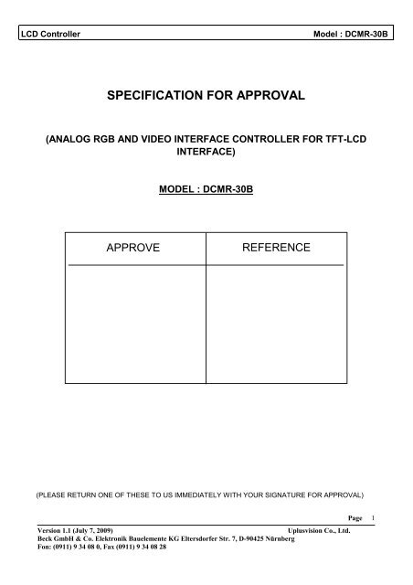
<strong>LCD</strong> Controller Model : <strong>DCMR</strong>-30B<br />
SPECIFICATION FOR APPROVAL<br />
(ANALOG RGB AND VIDEO INTERFACE CONTROLLER FOR <strong>TFT</strong>-<strong>LCD</strong><br />
INTERFACE)<br />
APPROVE<br />
D<br />
MODEL : <strong>DCMR</strong>-30B<br />
REFERENCE<br />
(PLEASE RETURN ONE OF THESE TO US IMMEDIATELY WITH YOUR SIGNATURE FOR APPROVAL)<br />
Version 1.1 (July 7, 2009) Uplusvision Co., Ltd.<br />
Beck GmbH & Co. Elektronik Bauelemente KG Eltersdorfer Str. 7, D-90425 Nürnberg<br />
Fon: (0911) 9 34 08 0, Fax (0911) 9 34 08 28<br />
Page<br />
1
<strong>LCD</strong> Controller Model : <strong>DCMR</strong>-30B<br />
Content of Specification<br />
1. Revision History ....................................................................................................... 4<br />
2. Product Overview ..................................................................................................... 5<br />
3. Features .................................................................................................................... 5<br />
4. System Configuration .............................................................................................. 6<br />
5. Electrical Specifications .......................................................................................... 6<br />
5.1. Video input timing ............................................................................................................................ 6<br />
5.2. Electrical Characteristics ................................................................................................................. 8<br />
6. Operational Setup .................................................................................................... 9<br />
7. OSD (On-Screen-Display) ...................................................................................... 10<br />
7.1. Main Menu ....................................................................................................................................... 10<br />
7.2. Sub-Menu : Color ............................................................................................................................ 11<br />
7.3. Sub-Menu : Image Setting ............................................................................................................. 12<br />
7.4. Sub-Menu : Position ....................................................................................................................... 13<br />
7.5. Sub-Menu : OSD Menu ................................................................................................................... 14<br />
7.6. Sub-Menu: Language ..................................................................................................................... 15<br />
7.7. Sub-Menu: Misc. ............................................................................................................................. 16<br />
8. Input Connectors ................................................................................................... 17<br />
8.1. Power Input connector ................................................................................................................... 17<br />
8.2. DVI Input connector, single link .................................................................................................... 17<br />
8.3. Analog RGB Input connector ........................................................................................................ 18<br />
Version 1.1 (July 7, 2009) Uplusvision Co., Ltd.<br />
Beck GmbH & Co. Elektronik Bauelemente KG Eltersdorfer Str. 7, D-90425 Nürnberg<br />
Fon: (0911) 9 34 08 0, Fax (0911) 9 34 08 28<br />
Page<br />
2
<strong>LCD</strong> Controller Model : <strong>DCMR</strong>-30B<br />
8.4. OSD, LED Interface Connector (J500) .......................................................................................... 18<br />
8.5. External Power Connector (J6) ..................................................................................................... 18<br />
8.6. DDC-2 Connector (J3) ......................................................................... Error! Bookmark not defined.<br />
9. Output Connectors for <strong>LCD</strong> Interface................................................................... 19<br />
9.1. LVDS Interface (J502) ..................................................................................................................... 19<br />
9.2. TTL - Interface (J503)........................................................................... Error! Bookmark not defined.<br />
9.3. Backlight Power Connector (J501) ............................................................................................... 19<br />
10. Mechanical Dimension .......................................................................................... 20<br />
11. Reliability ................................................................................................................ 21<br />
12. Absolute maximum ratings ................................................................................... 21<br />
13. Mounting rules ....................................................................................................... 21<br />
14. Operating Precautions ........................................................................................... 21<br />
15. General Cautions ................................................................................................... 22<br />
Version 1.1 (July 7, 2009) Uplusvision Co., Ltd.<br />
Beck GmbH & Co. Elektronik Bauelemente KG Eltersdorfer Str. 7, D-90425 Nürnberg<br />
Fon: (0911) 9 34 08 0, Fax (0911) 9 34 08 28<br />
Page<br />
3
<strong>LCD</strong> Controller Model : <strong>DCMR</strong>-30B<br />
1. Revision History<br />
Version Date Section Description<br />
Ver 1.0<br />
Ver 1.1<br />
01.12.07<br />
18.06.09<br />
All<br />
All<br />
<strong>DCMR</strong>-30B Specification<br />
<strong>DCMR</strong>-30B. Language update<br />
Version 1.1 (July 7, 2009) Uplusvision Co., Ltd.<br />
Beck GmbH & Co. Elektronik Bauelemente KG Eltersdorfer Str. 7, D-90425 Nürnberg<br />
Fon: (0911) 9 34 08 0, Fax (0911) 9 34 08 28<br />
Page<br />
4
<strong>LCD</strong> Controller Model : <strong>DCMR</strong>-30B<br />
2. Product Overview<br />
This board accepts standard analog RGB and SYNC (CRT like) signals from any VGA to UXGA<br />
video controller and standard single DVI (Digital Video Interface) signals. And also generates all the<br />
necessary control signals and the panel data to drive <strong>TFT</strong>-<strong>LCD</strong>s. This board supports to UXGA<br />
resolutions.<br />
The user interface includes Phase, Brightness, Contrast, Horizontal and Vertical Position<br />
adjustment, etc. via on-screen programming.<br />
3. Features<br />
Support up to SXGA / WXGA+.<br />
Input format detection<br />
Compatibility with standard VESA Mode and support user-defined mode.<br />
Smart engine for Phase/Image Position/Color calibration.<br />
Sharpness/Smooth filter enhancement.<br />
Support Sync On Green and various kinds of composite sync modes.<br />
Integrated 8-bit triple channel 165MHz ADC/PLL<br />
Dynamic contrast control / Independent color control.<br />
User friendly On Screen Display Menu to control image<br />
Auto-Adjust<br />
Color Adjust (Contrast, Brightness, etc.)<br />
Image Setting (Clock, Phase, etc.)<br />
Image Position<br />
OSD Setting<br />
Input Source Select<br />
Reset<br />
Power management support (DPMS - VESA compliant)<br />
Version 1.1 (July 7, 2009) Uplusvision Co., Ltd.<br />
Beck GmbH & Co. Elektronik Bauelemente KG Eltersdorfer Str. 7, D-90425 Nürnberg<br />
Fon: (0911) 9 34 08 0, Fax (0911) 9 34 08 28<br />
Page<br />
5
<strong>LCD</strong> Controller Model : <strong>DCMR</strong>-30B<br />
4. System Configuration<br />
Figure 1. System Block Diagram<br />
INV<br />
OSD<br />
J503 J501<br />
Con100<br />
DC 12V<br />
Con101<br />
5. Electrical Specifications<br />
External Power<br />
5.1. Video input timing<br />
J201<br />
DVI Signal<br />
Single and Dual LVDS<br />
Version 1.1 (July 7, 2009) Uplusvision Co., Ltd.<br />
Beck GmbH & Co. Elektronik Bauelemente KG Eltersdorfer Str. 7, D-90425 Nürnberg<br />
Fon: (0911) 9 34 08 0, Fax (0911) 9 34 08 28<br />
J500<br />
RTD 2533V<br />
Supported vertical refresh rtes for each modes as follow:<br />
640x350 70HZ<br />
640x350 85HZ<br />
720x400 70HZ<br />
720x400 85HZ<br />
640x480 60~85HZ<br />
800x600 56~85HZ<br />
J200<br />
RGB Signal<br />
Page<br />
6
<strong>LCD</strong> Controller Model : <strong>DCMR</strong>-30B<br />
832x624 ∗ 75HZ<br />
1024x768 60~85HZ<br />
1024x800* 73HZ<br />
1024x800* 85HZ<br />
1152x864* 60~85HZ<br />
1152x900* 66HZ<br />
1152x900* 76HZ<br />
1280x720* 60HZ<br />
1280x720* 75HZ<br />
1280x768* 60~75HZ<br />
1280x800* 60~75HZ<br />
1280x960* 60~85HZ<br />
1280x1024 60~85HZ<br />
1360x768* 60~75HZ<br />
1440x900* 60HZ<br />
1440x900* 75HZ<br />
1600x1200 60~85HZ<br />
1680x1050* 60HZ<br />
1680x1050* 75HZ<br />
1920x1200* 60~75HZ<br />
Sync. : H/V Separate, Sync On Green, Interlace<br />
Video - RGB Analog (75 Ohm, 0.7Vp-p)<br />
Up to 165Mhz standard single DVI resolution.<br />
∗ Depends on VGA signal source<br />
Version 1.1 (July 7, 2009) Uplusvision Co., Ltd.<br />
Beck GmbH & Co. Elektronik Bauelemente KG Eltersdorfer Str. 7, D-90425 Nürnberg<br />
Fon: (0911) 9 34 08 0, Fax (0911) 9 34 08 28<br />
Page<br />
7
<strong>LCD</strong> Controller Model : <strong>DCMR</strong>-30B<br />
5.2. Electrical Characteristics<br />
Item Symbol Condition MIN. TYP. MAX. Unit<br />
Supply Voltage ------ 7 12.0 Vdc<br />
Absolute Max.<br />
Rating<br />
Current<br />
Consumption 1<br />
------ 7 12.0 Vdc<br />
Board Only 0.4 0.5 0.55 A<br />
With HT15X15-<br />
D01<br />
In rush current ~<br />
Ext. power out<br />
Con101<br />
5V 5 V Module PW 5 V<br />
12V 12 V Module PW 12 V<br />
1 Test was performed with the BOE Hydis HT15X15-D01 and inverters which are made by Frontek Inc<br />
Version 1.1 (July 7, 2009) Uplusvision Co., Ltd.<br />
Beck GmbH & Co. Elektronik Bauelemente KG Eltersdorfer Str. 7, D-90425 Nürnberg<br />
Fon: (0911) 9 34 08 0, Fax (0911) 9 34 08 28<br />
A<br />
Page<br />
8
<strong>LCD</strong> Controller Model : <strong>DCMR</strong>-30B<br />
6. Operational Setup<br />
The OSD provides certain functions to have clear image and others.<br />
There are 5 buttons to control the OSD, PCB board and 1 LED for show status of board.<br />
OSD Board<br />
Function of each OSD key<br />
No. Button Switch Function<br />
1 Menu 1. Open the OSD Main Menu / Close the OSD Main Menu<br />
2 Select 1. Select a Item<br />
3 Down<br />
4 Up<br />
1. Move to downside on menu list<br />
2. decrease the value of selected item<br />
1. Move to upside on menu list<br />
2. Increase the value of selected item<br />
5 Power 1. Turn on power / Turn off power<br />
Hot-Key: One-click control<br />
- Auto adjust: “down” key<br />
- Source Switch (analog RGB, DVI) : “select” key<br />
Status LED<br />
- Green: Normal State<br />
MENU SELECT DOWN UP STATUS<br />
POWER<br />
- Amber flashing: DPMS mode (Can’t find signal)<br />
Version 1.1 (July 7, 2009) Uplusvision Co., Ltd.<br />
Beck GmbH & Co. Elektronik Bauelemente KG Eltersdorfer Str. 7, D-90425 Nürnberg<br />
Fon: (0911) 9 34 08 0, Fax (0911) 9 34 08 28<br />
Page<br />
9
<strong>LCD</strong> Controller Model : <strong>DCMR</strong>-30B<br />
7. OSD (On-Screen-Display)<br />
7.1. Main Menu<br />
Color: Adjust and correct the color<br />
Image Setting: Adjust and correct the image<br />
Position: Adjust the H-/V- Position of display<br />
OSD Menu: Adjust the On-Screen-Display<br />
Language: Select a language of OSD<br />
Misc.: All other settings<br />
Exit: Close the main menu<br />
Version 1.1 (July 7, 2009) Uplusvision Co., Ltd.<br />
Beck GmbH & Co. Elektronik Bauelemente KG Eltersdorfer Str. 7, D-90425 Nürnberg<br />
Fon: (0911) 9 34 08 0, Fax (0911) 9 34 08 28<br />
Page<br />
10
<strong>LCD</strong> Controller Model : <strong>DCMR</strong>-30B<br />
7.2. Sub-Menu : Color<br />
Contrast: Adjust the contrast of the image<br />
Brightness: Adjust the brightness of the image<br />
Color Adjust: Adjust the value of red, green and blue<br />
Color Temp: Adjust the color temperature<br />
Auto Color: Run the auto config of the Color<br />
Back: Back to main menu<br />
Version 1.1 (July 7, 2009) Uplusvision Co., Ltd.<br />
Beck GmbH & Co. Elektronik Bauelemente KG Eltersdorfer Str. 7, D-90425 Nürnberg<br />
Fon: (0911) 9 34 08 0, Fax (0911) 9 34 08 28<br />
Page<br />
11
<strong>LCD</strong> Controller Model : <strong>DCMR</strong>-30B<br />
7.3. Sub-Menu : Image Setting<br />
Clock: Adjust the clock of the image<br />
Phase: Adjust the phase of the image<br />
Gamma: Adjust gamma level of the image<br />
Sharpness: Adjust the sharpness of the image<br />
Auto Adjust: Run the auto config of the image<br />
Back: Back to main menu<br />
Version 1.1 (July 7, 2009) Uplusvision Co., Ltd.<br />
Beck GmbH & Co. Elektronik Bauelemente KG Eltersdorfer Str. 7, D-90425 Nürnberg<br />
Fon: (0911) 9 34 08 0, Fax (0911) 9 34 08 28<br />
Page<br />
12
<strong>LCD</strong> Controller Model : <strong>DCMR</strong>-30B<br />
7.4. Sub-Menu : Position<br />
H. Position: Adjust the H. position of the image<br />
V. Position: Adjust the V. position of the image<br />
Back: Back to main menu<br />
Version 1.1 (July 7, 2009) Uplusvision Co., Ltd.<br />
Beck GmbH & Co. Elektronik Bauelemente KG Eltersdorfer Str. 7, D-90425 Nürnberg<br />
Fon: (0911) 9 34 08 0, Fax (0911) 9 34 08 28<br />
Page<br />
13
<strong>LCD</strong> Controller Model : <strong>DCMR</strong>-30B<br />
7.5. Sub-Menu : OSD Menu<br />
OSD H. Pos.: Adjust the H. position of the OSD<br />
OSD V. Pos.: Adjust the H. position of the OSD<br />
OSD Timer: Adjust the OSD off timer<br />
Back: Back to main menu<br />
Version 1.1 (July 7, 2009) Uplusvision Co., Ltd.<br />
Beck GmbH & Co. Elektronik Bauelemente KG Eltersdorfer Str. 7, D-90425 Nürnberg<br />
Fon: (0911) 9 34 08 0, Fax (0911) 9 34 08 28<br />
Page<br />
14
<strong>LCD</strong> Controller Model : <strong>DCMR</strong>-30B<br />
7.6. Sub-Menu: Language<br />
Korean: Select a Korean<br />
English: Select a English<br />
Deutsch: Select a Germany<br />
Version 1.1 (July 7, 2009) Uplusvision Co., Ltd.<br />
Beck GmbH & Co. Elektronik Bauelemente KG Eltersdorfer Str. 7, D-90425 Nürnberg<br />
Fon: (0911) 9 34 08 0, Fax (0911) 9 34 08 28<br />
Page<br />
15
<strong>LCD</strong> Controller Model : <strong>DCMR</strong>-30B<br />
7.7. Sub-Menu: Misc.<br />
Signal Source: Select the input source<br />
Reset: Factory reset<br />
Back: Back to main menu<br />
Version 1.1 (July 7, 2009) Uplusvision Co., Ltd.<br />
Beck GmbH & Co. Elektronik Bauelemente KG Eltersdorfer Str. 7, D-90425 Nürnberg<br />
Fon: (0911) 9 34 08 0, Fax (0911) 9 34 08 28<br />
Page<br />
16
<strong>LCD</strong> Controller Model : <strong>DCMR</strong>-30B<br />
8. Input Connectors<br />
8.1. Power Input connector<br />
Power input connector (P100/) : 2.5 Power DC Jack<br />
Pin No. Symbol Description<br />
1 GND GND<br />
2 Vin +12Vdc<br />
Power input connector (Con100) : 20022WR-02<br />
Pin No. Symbol Description<br />
1 GND GND<br />
2 Vin +12Vdc<br />
3 GND GND<br />
4 GND GND<br />
8.2. DVI Input connector, single link<br />
DVI Input connector (J201): 20022WR-13<br />
Pin No. Symbol Signal Name Pin No. Symbol Signal Name<br />
1 SDA DDC Data 8 GND Ground<br />
2 SCL DDC Data Clock 9 RX0+ DVI Data 0 +<br />
3 RX2+ DVI Data 2 + 10 RX0- DVI Data 0 -<br />
4 RX2- DVI Data 2 - 11 GND Ground<br />
5 GND Ground 12 RXC+ DVI Clock +<br />
6 RX1+ DVI Data 1 + 13 RXC- DVI Clock -<br />
7 RX1- DVI Data 1 -<br />
Version 1.1 (July 7, 2009) Uplusvision Co., Ltd.<br />
Beck GmbH & Co. Elektronik Bauelemente KG Eltersdorfer Str. 7, D-90425 Nürnberg<br />
Fon: (0911) 9 34 08 0, Fax (0911) 9 34 08 28<br />
Page<br />
17
<strong>LCD</strong> Controller Model : <strong>DCMR</strong>-30B<br />
Analog RGB Input connector<br />
RGB Input connector (J200) : 20022WR-13<br />
Pin No. Symbol Signal Name Pin No. Symbol Signal Name<br />
1 HSYNC Horizontal Sync 8 GND Ground<br />
2 GND Ground 9 RED Analog RED<br />
3 VSYNC Vertical Sync 10 GND Ground<br />
4 GND Ground 11 SCL DDC Data Clock<br />
5 BLUE Analog BLUE 12 SDA DDC Data<br />
6 GND Ground 13 NC No Connect<br />
7 GREEN Analog GREEN<br />
8.3. OSD, LED Interface Connector (J501)<br />
12505WR-14 by Yeonho (2mm Pitch / 14 Pin)<br />
Pin No. Symbol Signal Name Pin No. Symbol Signal Name<br />
1 LED_G LED GREEN 8 NC No Connect<br />
2 LED_R LED RED 9 NC No Connect<br />
3 GND Ground 10 KEY4 Up KEY<br />
4 KEY1 Power KEY 11 KEY5 Select KEY<br />
5 NC No Connect 12 KEY6 IR_INT<br />
6 KEY2 Menu KEY 13 NC No Connect<br />
7 KEY3 Down KEY 14 NC No Connect<br />
8.4. External Power Connector (Con101)<br />
20022WR-04/NC by Yeonho (2mm Pitch / 4 Pin)<br />
Pin No. Symbol Description<br />
1 12 DC 12V<br />
2 GND Ground<br />
3 GND Ground<br />
4 5 DC 5V<br />
Version 1.1 (July 7, 2009) Uplusvision Co., Ltd.<br />
Beck GmbH & Co. Elektronik Bauelemente KG Eltersdorfer Str. 7, D-90425 Nürnberg<br />
Fon: (0911) 9 34 08 0, Fax (0911) 9 34 08 28<br />
Page<br />
18
<strong>LCD</strong> Controller Model : <strong>DCMR</strong>-30B<br />
9. Output Connectors for <strong>LCD</strong> Interface<br />
9.1. LVDS Interface (J500)<br />
12507WR-30 by Yeonho (1.25mm Pitch / 30 Pin)<br />
Pin No Description Pin No. Description Pin No. Description<br />
1 VCC 11 RXOIN1 - 21 RXEIN0 +<br />
2 VCC 12 RXOIN1 + 22 RXEIN1 -<br />
3 VCC 13 RXOIN2 - 23 RXEIN1 +<br />
4 VCC 14 RXOIN2 + 24 RXEIN2 -<br />
5 NC 15 RXOCKIN - 25 RXEIN2 +<br />
6 GND 16 RXOCKIN + 26 RXECKIN -<br />
7 GND 17 RXOIN3 - 27 RXECKIN +<br />
8 GND 18 RXOIN3 + 28 RXEIN3 -<br />
9 RXOIN0 - 19 GND 29 RXEIN3 +<br />
10 RXOIN0 + 20 RXEIN0 - 30 GND<br />
9.2. Backlight Power Connector (J503)<br />
12505WR-07 by Yeonho (1.25mm Pitch / 7 Pin)<br />
Pin No. Symbol Description<br />
1 GND Ground<br />
2 GND Ground<br />
3 GND Ground<br />
4 ADJ 0.0 ~ 5.0 Vdc<br />
5 On / Off 0 / 5 Vdc(High Active)<br />
6 Vin +12Vdc Input<br />
7 Vin +12Vdc Input<br />
Version 1.1 (July 7, 2009) Uplusvision Co., Ltd.<br />
Beck GmbH & Co. Elektronik Bauelemente KG Eltersdorfer Str. 7, D-90425 Nürnberg<br />
Fon: (0911) 9 34 08 0, Fax (0911) 9 34 08 28<br />
Page<br />
19
<strong>LCD</strong> Controller Model : <strong>DCMR</strong>-30B<br />
10. Mechanical Dimension<br />
Version 1.1 (July 7, 2009) Uplusvision Co., Ltd.<br />
Beck GmbH & Co. Elektronik Bauelemente KG Eltersdorfer Str. 7, D-90425 Nürnberg<br />
Fon: (0911) 9 34 08 0, Fax (0911) 9 34 08 28<br />
Page<br />
20
<strong>LCD</strong> Controller Model : <strong>DCMR</strong>-30B<br />
11. Reliability<br />
Test item Condition<br />
High temperature storage test +70°<br />
Low temperature storage test -20°<br />
High temperature operation test +60°<br />
Low temperature operation test -10°<br />
Vibration test<br />
Shock test<br />
Altitude test<br />
Humidity test<br />
12. Absolute maximum ratings<br />
Test item Condition<br />
High temperature storage +70°<br />
Low temperature storage -20°<br />
High temperature operation +60°<br />
Low temperature operation 2 -10°<br />
13. Mounting rules<br />
• You must mount a module using holes arranged in four corners.<br />
• Avoid any bend force during mounting<br />
14. Operating Precautions<br />
• The spike noise causes the mis-operation of circuits. It should be lower than following<br />
voltage : V=¡200mV(Over and under shoot voltage)<br />
• Be careful for condensation at sudden temperature change. Condensation makes<br />
damage to electrical contacted parts.<br />
• Module has high frequency circuits. Sufficient suppression to the electromagnetic<br />
interference shall be done by system manufacturers. Grounding and shielding methods<br />
may be important to minimized the interference<br />
2 Phase shift or clock shift can appear between -10°C and 0°C<br />
Version 1.1 (July 7, 2009) Uplusvision Co., Ltd.<br />
Beck GmbH & Co. Elektronik Bauelemente KG Eltersdorfer Str. 7, D-90425 Nürnberg<br />
Fon: (0911) 9 34 08 0, Fax (0911) 9 34 08 28<br />
Page<br />
21
<strong>LCD</strong> Controller Model : <strong>DCMR</strong>-30B<br />
15. General Cautions<br />
• Never touch the inverter(dc-ac) while power is connected. Inverter should be properly<br />
mounted in the system. All transformers on the inverter should be covered with non-<br />
conductive heat-resistant material. Inverter is a source of very high voltages.<br />
Precaution must be taken to avoid electrical shocks.<br />
• When preparing a cable for a specific flat panel, always refer to appropriate cable pin-<br />
out and flat panel specification. Always check the flat panel signals before connecting<br />
the cable. Any incorrect pin connection may damage the flat panel permanently.<br />
• Should you need any technical help, please contact Beck GmbH & Co. Elektronik<br />
Bauelemente KG<br />
Version 1.1 (July 7, 2009) Uplusvision Co., Ltd.<br />
Beck GmbH & Co. Elektronik Bauelemente KG Eltersdorfer Str. 7, D-90425 Nürnberg<br />
Fon: (0911) 9 34 08 0, Fax (0911) 9 34 08 28<br />
Page<br />
22