Specification - OLED-LCD-TFT
Specification - OLED-LCD-TFT
Specification - OLED-LCD-TFT

Create successful ePaper yourself
Turn your PDF publications into a flip-book with our unique Google optimized e-Paper software.
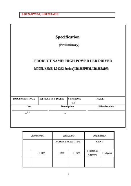
LD1263PWM, LD1263ADN<br />
DOCUMENT NO.:<br />
Ver.<br />
___________________________<br />
_0.1<br />
<strong>Specification</strong><br />
(Preliminary)<br />
PRODUCT NAME: HIGH POWER LED DRIVER<br />
MODEL NAME: LD1263 Series( LD1263PWM, LD1263ADN)<br />
EFFECTIVE DATE:<br />
VERSION:<br />
0.1<br />
Description<br />
____________________________<br />
_<br />
1<br />
PAGE:<br />
APPROVED CHECKED PREPARED<br />
JASON Lee 2011/10/07 KENT<br />
□VP □EE □ME<br />
Effective date<br />
____________________________<br />
□EMI &<br />
SAFETY<br />
□Layout
LD1263PWM, LD1263ADN<br />
Edition History<br />
Vo Initial Version<br />
Note<br />
2011/10/08<br />
2
LD1263PWM, LD1263ADN<br />
CONTENT<br />
1.0 General Description: ........................................................................................................4<br />
1.1 Feature:................................................................................................................... 4<br />
1.2 Application: ............................................................................................................ 4<br />
2.0 GENERAL SPECIFICATION: .............................................................................. 5<br />
3.0 Ordering Information.............................................................................................. 5<br />
4.0 BLOCK DIAGRAM:..................................................................................................... 6<br />
5.0 Board Dimension: ....................................................................................................... 7<br />
5.1 LAYOUT & Dimension........................................................................................... 7<br />
5.2 Picture : .................................................................................................................... 8<br />
6. Connector I/O definition ................................................................................................. 9<br />
6.1 Input Pin Definition ................................................................................................. 9<br />
6.2 Output Pin Definition .......................................................................................... 10<br />
7.0 Electrical Absolute Rating........................................................................................... 12<br />
8.0 Electrical Rating.................................................................................................. 12<br />
9.0 Application Note: ................................................................................................... 13<br />
3
LD1263PWM, LD1263ADN<br />
1.0 General Description:<br />
LD1263 series LED Driver is High Power & High efficiency Led driver board which is<br />
intended to design for Led based panel to replace the CCFL with good performance and<br />
quality.<br />
1.1 Feature:<br />
By model option to support linear analog voltage or digital pulse width modulation<br />
(PWM) to adjust LED brightness<br />
Support negative Analog voltage(LD1263ADN)<br />
Support positive Pulse modulation (LD1263PWM)<br />
ON/OFF Pin to enable or disable Led driver<br />
Independent Current output<br />
Over Voltage protection<br />
LED Output Short circuit protection<br />
12V DC input (default model ).<br />
5V DC input (optional model)<br />
Normally 90% high efficiency transformation<br />
Adjustable for the Led output Current by resistor (Rset)<br />
Thermal protection<br />
RoHs Compliant<br />
1.2 Application:<br />
LED Panel LightBar<br />
LED relative Appliances<br />
4
LD1263PWM, LD1263ADN<br />
2.0 GENERAL SPECIFICATION:<br />
Item<br />
Description<br />
Length 93.4mm<br />
Width 32.5mm<br />
Input Voltage 5V or 12V+-10%<br />
Output Voltage 30V(5V IN), 52V(12V IN)<br />
Max. Output current TBD<br />
Line Ripple =85 %<br />
Dimming Analog(0-5V) or PWM( 200Hz is recommended)<br />
Max output Watt. < 12.5 Watt<br />
Working environment<br />
Life Cycle >=40K hours<br />
3.0 Ordering Information<br />
LD1263PWM_XXXXXXXX----LD1263 with PWM dimming , XXXXXXXXX is Panel P/N<br />
LD1263ADN_XXXXXXXX ------LD1263 with Analog dimming, XXXXXXXX is Panel P/N<br />
5
LD1263PWM, LD1263ADN<br />
4.0 BLOCK DIAGRAM:<br />
12V/5V DC IN<br />
GND<br />
ON/OFF<br />
0 to 5V analog<br />
PWM<br />
PWM<br />
Control<br />
Fig 1 Block Diagram<br />
6<br />
DC/DC<br />
PRE-BOOST<br />
DC/DC<br />
POST-BOOST<br />
Current Sense<br />
& Control<br />
LED<br />
OUTPUT
LD1263PWM, LD1263ADN<br />
5.0 Board Dimension:<br />
5.1 LAYOUT & Dimension<br />
M2 Screw Hole<br />
JP2 5PIN ,PIN1<br />
7<br />
M2 Screw Hole<br />
J1,15PIN,Molex
LD1263PWM, LD1263ADN<br />
5.2 Picture :<br />
PIN 5 PIN 1 PIN 15 PIN 1<br />
JP2: PHR,2.0mm J1: Molex 1.25mm(53261-1571)<br />
PIN 1: PWM (LD1263PWM only )<br />
PIN2: Analog Dimming ( LD1263ADN only )<br />
PIN 3: Enable<br />
PIN 4: Ground<br />
PIN 5: 12V/5V DCIN<br />
8<br />
PIN 1: VCH1- PIN 9: VLED+<br />
PIN 2: VCH2- PIN 10: VCH7-<br />
PIN 3: VCH3- PIN 11: VCH8-<br />
PIN 4: VCH4- PIN 12: VCH9-<br />
PIN 5: VCH5- PIN 13: VCH10-<br />
PIN 6: VCH6- PIN 14: VCH11-<br />
PIN 7: VLED+ PIN 15: VCH12-<br />
PIN 8: VLED+
LD1263PWM, LD1263ADN<br />
6. Connector I/O definition<br />
6.1 Input Pin Definition<br />
Input Side : JP2 , 5 PIN , JST ,PHR connector, itch=2.0mm<br />
PIN PIN NAME<br />
5 VDD<br />
4 GND<br />
3 ENABLE<br />
2 Analog dimming<br />
1 PWM Dimming<br />
DC 12V Input<br />
GND PIN<br />
9<br />
Description<br />
LED ON/OFF control, High is for enable ,Low is for disable.<br />
The range is 0V to 5V<br />
0 to 5V analog voltage dimming. 0V get Max. brightness,<br />
5V get Min. brightness. (negative dimming)<br />
(This pin is supported by LD1263ADN only)<br />
PWM : 150Hz to 500 Hz, 200 Hz is recommended<br />
( this pin is supported by LD1263PWM only )<br />
PWM Operation : Frequency can be from 100 Hz up 500 Hz<br />
5 V<br />
0 V<br />
note<br />
note
Brightness<br />
LD1263PWM, LD1263ADN<br />
Dark<br />
0V 5V<br />
Positive Dimming Negative Dimming<br />
6.2 Output Pin Definition<br />
Brightness<br />
Dark<br />
OUTPUT SIDE 1: J2: 12PIN, Pitch=0.5mm, For CMO Panel<br />
Description<br />
PIN PIN NAME<br />
1 Led 1 Led Lightbar Channel<br />
2 Led 2 Led Lightbar Channel<br />
3 Led 3 Led Lightbar Channel<br />
4 Led 4 Led Lightbar Channel<br />
5<br />
6 VLED LED High voltage<br />
7 VLED LED High voltage<br />
8<br />
9 Led 5 Led Lightbar Channel<br />
10 Led 6 Led Lightbar Channel<br />
11 Led 7 Led Lightbar Channel<br />
12 Led 8 Led Lightbar Channel<br />
10<br />
0 V 5V
LD1263PWM, LD1263ADN<br />
OUTPUT SIDE 2: 2 PIN, BHSR-02VS-1 (JST)<br />
PIN PIN NAME<br />
11<br />
Description<br />
1 LED_Positive LED Positive Voltage<br />
2 LED_Negative LED Negative Voltage<br />
Output Side 3: J1 : 15 Pin, Molex 53261-1571,pitch=1.25mm<br />
PIN PIN NAME<br />
Description<br />
1 VCH1- LED channel 1<br />
2 VCH2- LED channel 2<br />
3 VCH3- LED channel 3<br />
4 VCH4- LED channel 4<br />
5 VCH5- LED channel 5<br />
6 VCH6- LED channel 6<br />
7 VLED+ LED High Voltage<br />
8 VLED+ LED High Voltage<br />
9 VLED+ LED High Voltage<br />
10 VCH7- LED channel 7<br />
11 VCH8- LED channel 8<br />
12 VCH9- LED channel 9<br />
13 VCH10- LED channel 10<br />
14 VCH11- LED channel 11<br />
15 VCH12- LED channel 12
LD1263PWM, LD1263ADN<br />
7.0 Electrical Absolute Rating<br />
Parameter Min. Value Max. value Unit<br />
VDD 5 V<br />
Enable Pin -- 8 V<br />
Neg. Dimming -- 6 V<br />
Pos. Dimming -- 6 V<br />
8.0 Electrical Rating<br />
Parameter<br />
Symbol<br />
Min.<br />
12<br />
Typical Max. Unit<br />
VDD 5 V<br />
Enable Pin<br />
Neg. Dimming<br />
Pos. Dimming<br />
ViH 2.0 3.3~5 8 V<br />
ViL ___ 0 0.6 V<br />
ViH 3.3 note 5 6 V<br />
ViL ------ 0 0.6 V<br />
ViH 3.3 note 5 6<br />
ViL ____ 0 0.6<br />
V
LD1263PWM, LD1263ADN<br />
9.0 Application Note:<br />
1. How to calculate and decide the independent current on each Led<br />
channel ?<br />
The LD1263 use different Rset value to decide to the Independent the LED current.<br />
Here,the Rset resistor on the LD1263 series is R11,which is located and shown as<br />
below,<br />
the Rset value is s set by the formula:<br />
Rset= 1200V/ I , where I is LED independent current.<br />
For Example: Rset=30K, then the Led driver will maintain 40mA in each independent LED<br />
channel<br />
For Example : Rset=60K, then the LED driver will maintain 20mA in each independent<br />
LED channel<br />
Please note the independent current on each channel should work with the different<br />
Led cable wiring configuration supported by different Panel model in order to<br />
match the Panel Led structure. The wrong Led cable might cause the panel fatal<br />
damage.<br />
2: How to tell the difference between the LD1263_PWM and<br />
LD1263_ADN ??<br />
The LD1263PWM driver is input by PWM to control the LED dimming, however<br />
The LD1263ADN driver is input by analog voltage from 0V to 5V to adjust the dimming,<br />
the difference between 2Led drivers is to check specific resistors assembly or not<br />
13<br />
R11 is Rset resistor
LD1263PWM, LD1263ADN<br />
The table is shown as blow :<br />
Model Name<br />
LD1263PWM<br />
PIN out<br />
PIN 1 PWM<br />
Dimming Control<br />
14<br />
Special Resistors reference<br />
R8,R38 is NC (not assembly)<br />
R39 is On(assembly)<br />
LD1263ADN PIN 2 Analog Voltage R38,R39 is NC (not assembly)<br />
R38<br />
R39<br />
R8<br />
R8 is On(assembly)
LD1263PWM, LD1263ADN<br />
Accessory Option<br />
The LED cable to Panel with Cvilux or compatible connector<br />
FFC cable with 0.5mm<br />
15
LD1263PWM, LD1263ADN<br />
16